R E S E A R C H
Open Access
High-quality binary fringe patterns
generation by combining optimization
on global and local similarity
Feng Lu
1*, Chengdong Wu
1and Jikun Yang
2Abstract
Background:The recently proposed optimized dithering techniques can improve measurement quality. However,
the objective function in these optimization methods just qualifies the global similarity of the pattern while the global optimization methods ignore the influences of local structure.
Method:In order to get high quality binary dithered patterns, this paper presents an algorithm which combines optimization on global and local similarity and implements it in the whole-fringe optimization.
Results:Both the simulation and experimental results demonstrate that the proposed algorithm can achieve binary fringe patterns with higher phase quality and less intensity difference. The fringe patterns based on the proposed method can get high quality measurement results.
Conclusion:The proposed method can get high quality binary dithered patterns under different defocusing levels
by combining global similarity and local structure similarity. The proposed method can improve the robustness to the amounts of defocusing.
Keywords:3D measurement profilometry, Bianry defocusing, Dithering, Optimization
Background
Digital fringe projection (DFP) techniques based on sinusoidal fringe patterns have been widely used for high-quality 3D shape measurement due to their flexi-bility and speed [1]. However, there are major limita-tions of the conventional DFP technique: high speed measurement (i.e., typically 120 Hz) and projection nonlinearity, which make it difficult to be applied to high-speed measurement [2].
To overcome these limitations, two categories of methods are proposed: the 1-D pulse width modulation methods [3,4] and the 2-D area modulation methods [5, 6]. The former separates the fundamental frequency from high frequency harmonics by either shifting or eliminating high frequency harmonics. This method is successful to meet the requirement of high speed meas-urement, but this technique also has the defects: (1)
when the fringe stripes are wide, the improvements have been limited [7], (2) because the pulse width modulation (PWM) technique is one-dimensional pattern, it cannot fully take advantage of the two-dimensional binary de-focusing technique [8]. Xian and Su [9] propose the area-modulation technique, which can generate high-quality sinusoidal fringe patterns for precise micro manufacturing. In 2012, Lohry and Zhang [10] propose a technique to approximate the triangular waveform by modifying 2 × 2 pixels so that it can get better measure-ment results. However, if the fringe stripes are wide, it is difficult to achieve high-quality patterns.
Dithering techniques have been extensively used to produce high quality fringe pattern that can approximate the ideal sinusoidal patterns more closely after defocus-ing [11, 12]. The superiority of dithering techniques is that it operates a two-dimensional process that can ma-nipulate the noise more flexibly and imitate sinusoidal fringes, especially it can get high quality fringe pattern for large period. Over the past years, some researchers have developed the dithering techniques to make * Correspondence:[email protected]
1Faculty of Robot Science and Engineering, Northeastern University,
Shenyang, China
Full list of author information is available at the end of the article
significant improvements to fringe pattern quality. These studies include: Bayer method [13], error diffu-sion method [14] and genetic method [15]. The qual-ity of the pattern based on optimization method is higher than that of other methods, and the genetic method improves the phase drastically. However the dithering techniques are originally developed for glo-bal similarity [16, 17].
In order to improve local details and the quality of fringe patterns, a lot of research has been carried out to optimize the dithered fringe patterns for phase-shifting profilometry. The optimization can be carried out in either intensity or phase domain. The former approach [18, 19] tries to minimize the error between the defocused halftone pattern and a sinusoidal fringe pattern while the latter approach [20] tries to minimize the phase error achieved with the defocused halftone patterns. Since the quality of measurement is determined by the phase error, the phase-based optimization tends to optimize the measurement quality directly while the intensity-based optimization does not. However, the performance of current phase-based optimization method is more sensitive to the extent of defocusing which may not be controlled precisely in practical situations [21]. The intensity-based method is robust to the amounts of defocusing. Whereas, these optimization methods just focus the global intensity similarity while ignore the influences of local structure. The intensity-based optimization and phase-based optimization are always implemented in a small patch of the fringe pattern and the best patch is tiled through symmetry and periodicity. In the process of optimization, manual selection of the best patch is very tedious and time-consuming.
This paper proposes a new optimization framework to improve the fringe pattern quality. In order to make sure global and local similarity between the ideal pattern and the defocused dithering pattern. We propose an objective function which weighted combines normalized mean squared error and struc-tural similarity index measure. The global similarity is presented by normalized mean squared error and the local similarity is presented by structural similar-ity index measure. The goal of optimization is to minimize the object function between the defocused binary pattern and its corresponding ideal sinusoidal pattern.
The remainder of this paper is organized as follows. Section Method, we briefly review the principle of three-step phase-shifting algorithm, the principle of the object function and the whole fringe optimization framework. Section Results and discussion, we present the experi-mental results. Section Conclusion provides the conclu-sion of this paper.
Method
Three-step phase-shifting algorithm
In this paper, three-step phase-shifting algorithm with a phase shift 2π/3is applied. Because it need the least for-mulas for its simplicity and speed. The sinusoidal light intensity can be described as:
I1ðx;yÞ ¼A xð ;yÞ þB xð ;yÞcos½φðx;yÞ ð1Þ
I2ðx;yÞ ¼A xð ;yÞ þB xð ;yÞcos½φðx;yÞ þπ=3 ð2Þ
I3ðx;yÞ ¼A xð ;yÞ þB xð ;yÞcos½φðx;yÞ þ2π=3 ð3Þ
WhereA(x,y) is the average intensity. B(x,y) is the in-tensity modulation.φ(x,y) is the phase needed to be cal-culated. Based on the Eqs.(1–3), the φ(x,y) can be gotten.
φðx;yÞ ¼ tan−1 pffiffiffi3ðI1−I3Þ=ð2I2−I1−I3Þ
h i
ð4Þ
Notably, the environmental noise can be eliminated by subtraction of different patterns. The solved phase from Eq. (4) is wrapped in range (−π,π]. After φ(x,y) is un-wrapped, the absolute phase can be obtained.
Objection function
Dithering optimization technique has been researched in reducing its overall phase error. The objective function of all these optimization techniques is to get the best fit of the binary patterns to the corresponding ideal sinus-oidal pattern [14]. The optimization process can be de-scribed as the norm function such as norm Frobenius function:
min
B;G kI xð ;yÞ−G xð ;yÞ B xð ;yÞk ð5Þ
Where ‖·‖represents the norm Frobenius.I(x,y) is the ideal sinusoidal intensity pattern.G(x,y) represents a 2D Gaussian function.B(x,y) is the 2D binary pattern. * rep-resents convolution. The optimization function evaluates the global intensity similarity between the dithering pat-tern and its corresponding ideal patpat-tern, but it just con-siders the global similarity without focusing on local structure similarity. In addition, the global optimization is a very time-consuming process and it is difficult to solve the problem by using the objective function be-cause of the NP problem [18].
structural similarity index measure (SSIM). The WSF
can be expressed as follows:
WSF¼ωnNMSE Ið ;IdÞ þωsð1−SSIM Ið;IdÞÞ ð6Þ
Where NMSE(I,Id) measures the global similarity and
SSIM(I,Id) measures the local similarity, respectively.
WSFgets the synthetic error between the ideal patternI
and the dithering pattern Id. The ωn and ωs are the weight factors (ωn+ωs= 1). Becauseωnis the coefficient of the normalized mean squared error, it represents the weight of global similarity, such as period, peak, trough and symmetric axis and so on. Whileωsis the coefficient of structural similarity index measure which represents the weight of local similarity such as local luminance, contrast and structure and so on. In this paper, ωn and
ωsare empirically set to be 0.7 and 0.3 respectively. First a global intensity similarity is introduced into the
WSFexpression. TheNMSE(I,Id) can evaluate the global intensity similarity between the dithering pattern and the corresponding ideal pattern. TheNMSE(I,Id) can be shown as:
NMSE Ið;IdÞ ¼
P
H
P
WðI xð ;yÞ−Idðx;yÞÞ2
P
H
P
WðI xð ;yÞÞ
2 ð7Þ
Where H and W respectively represent height and width of the pattern. The NMSE(I,Id) method reflects the whole fringe pattern intensity statistical errors. Thus, the smaller theNMSE(I,Id) is, the better the whole pat-tern quality becomes. However NMSE(I,Id) only focuses on the global similarity, so SSIM(I,Id) is introduced as an optimization term to evaluate the local structure similarity between the dithering pattern and the corre-sponding ideal pattern. The whole fringe pattern is di-vided into P elements by the neighborhood window.
SSIM(I,Id) is calculated in the neighborhood window and the window size is designed based on the whole pat-tern. For example, in this paper, the size of captured image is 768*1024. Because the vertical fringe pattern is used, the window size is designed according to the width of fringe pattern. 24 pixels are neglected from the 1024 pixels and 1000 pixels are kept. For the whole fringe pat-tern, it can be divided into 20 parts where every part contains 50 pixels. Every part is analyzed by using lumi-nance, contrast and structure. At last every optimized section is connected directly without complex comput-ing because we optimize the frcomput-inge pattern in a whole pattern. In the local structure, the comparison between the ideal pattern and dithering pattern focuses on three parts: luminance, contrast and structure. First the local structure function (LSF) should be generated and the structural intensity error is calculated by comparing the
LSFbetweenI(x,y) andId(x,y).
The calculation process of LSF(x,y) is shown as fol-lowing and we setI(x,y) as an example:
Luminance: Luminance function can be designed as
l(x,y), as shown in Eq.(8):
l xð ;yÞ ¼ 2SxSyþc1 S2
xþS2yþc1
ð8Þ
Where c1is a constant (here c1= 1) to avoid singular-ity. Based on the theory of references [22, 23], every Sx and Sy can respectively be calculated by using formula:
Sx¼ P i¼1
W
xiandSy¼ P
i¼1
H
yiwherexiis the intensity of every
row and yi is the intensity of every column.Wand His the width and height of every part.
Contrast: Contrast function can be designed as c(x,y). It is similar to Eq.(8), but it usesσxandσyto express the estimation of the contrast, as show in Eq.(9):
c xð ;yÞ ¼σ22σxσyþc2
xþσ2yþc2 ð
9Þ
Where c2 is also constant (here c2= 1) to avoid singularity.
If the intensity average value of every row is Si, the standard deviation σx can be calculated by using
for-mula: σx¼
ffiffiffiffiffiffiffiffiffiffiffiffiffiffiffiffiffiffiffiffiffiffiffiffiffiffi 1 N−1 P i¼1 N
ðxi−SiÞ r
and σy can be gotten with
the same form.
Structure: Structural function can be designed as s(x,
y). It uses the correlation between the ideal pattern and dithering pattern to measure the structural similarity, as shown in Eq.(10):
s xð ;yÞ ¼σ σxyþc3
xþσyþc3 ð
10Þ
Where the c3is similar to c1and c2 (here c3= 1) and
the standard deviation σxy is solved for σxy¼N1−1 P i¼1
N
ðxi−
SxÞðyi−SyÞ.
The local weighted function (LWF) is generated by weighted combing the luminance function、contrast function and structural function, as shown in Eq. (11)
LSF xð ;yÞ ¼l xð ;yÞαc xð ;yÞβs xð ;yÞγ ð11Þ
Whereα,βandγare used to be weighted between lu-minance function、contrast function and structural function. Usuallyα,βandγare set to 1.
The ideal sinusoidal fringe patternI(x,y) and dithering pattern Id(x,y) have the same process to calculate the
SSIM Ið;IdÞ ¼
ffiffiffiffiffiffiffiffiffiffiffiffiffiffiffiffiffiffiffiffiffiffiffiffiffiffiffiffiffiffiffiffiffiffiffiffiffiffiffiffiffiffiffiffiffiffiffiffiffiffiffiffiffiffiffiffiffiffiffiffiffiffiffi XN
x¼1
XM
y¼1
LSF xð ;yÞ−LSFdðx;yÞ
ð Þ2
v u u t
ð12Þ
Where I(x,y) is the pixel intensity of desired ideal si-nusoidal fringe. Id(x,y) is the pixel intensity of the Gaussian filtered dithering fringe.
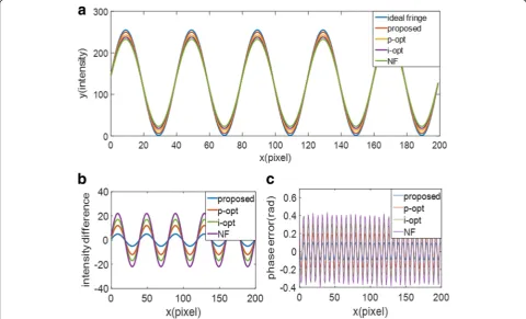
Phase-based optimization (p-opt) and intensity-based optimization (i-opt) are also two main categories to im-prove the quality of fringe patterns. In order to show the superiority of the proposed optimization method, we compare it with the norm Frobenius (NF) [17], the p-opt [18], i-opt [19] and ideal sinusoidal fringe patterns under the same condition. Figure 1 shows the effectiveness of the proposed method. Figure1ashows the cross-section comparison between the ideal sinusoidal curve and fringe patterns with different optimization. Figure 1b and cgive the intensity difference and phase difference with p-opt, i-opt, NF and the proposed method. From the results we can find that the fringe pattern based on phase optimization has less intensity difference than that based on intensity optimization. It means phase-based optimization can generate better quality fringe pattern than intensity-based optimization. Compared with these two methods, the proposed method has the least
intensity difference which means the quality is the best among these optimization methods, while the quality based on the norm Frobenius is the worst because inten-sity difference is the largest. By analyzing the phase er-rors, it can also be found that the phase error based on NF is the largest. Phase-based optimization is superior to the intensity-based optimization while the proposed optimization can generate the least phase errors. It proves the advantage of dithering fringe pattern after optimization of WSF. It can generate better quality fringe pattern with less intensity difference and less phase errors.
BecauseNFjust compares the global similarity without considering the local structure similarity and other methods are designed for the local details, in the follow-ing section we just compare the intensity-based optimization, phase-based optimization and the pro-posed optimization method.
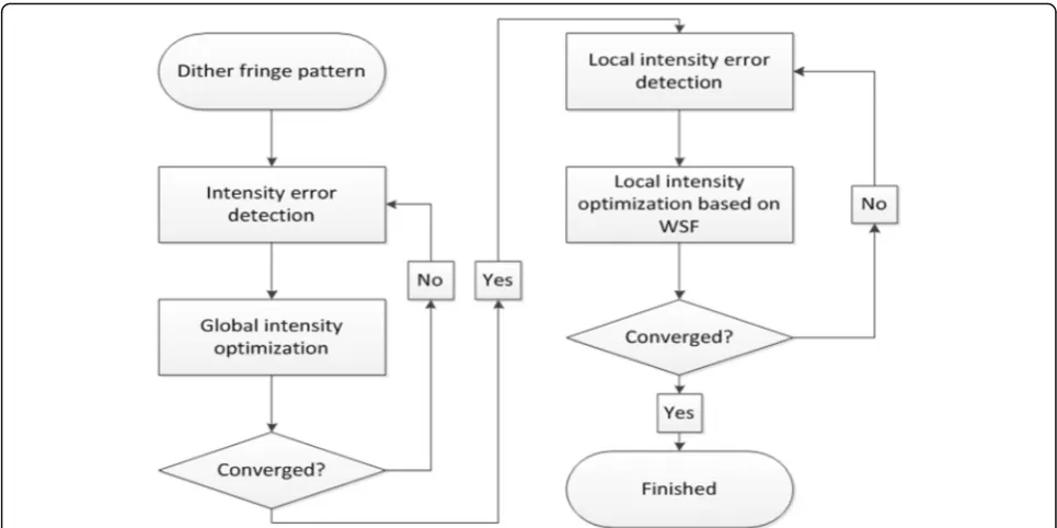
Implementation in the whole fringe optimization framework
Figure2 is a flowchart showing the proposed algorithm implemented in the whole fringe optimization and the optimization process is implemented as:
Step 1: Intensity error pixel detection. Intensity absolute error mapΔI(x,y) is calculated byΔI(x,y) = |I(x,y)−Id(x,y)|,
where I(x,y) is the intensity of ideal sinusoidal fringe and
Id(x,y) is the intensity of Gaussian filtered binary fringe. When the pixels with intensity error are bigger than a certain threshold, they can be defined as error pixels. In this paper, ten fringe patterns are projected to a flat and a series of images are captured. The same period of sinusoidal fringe pattern is designed and compared with captured image. The mean differ-ence value is used as the threshold.
Step 2: Error pixel reassignment. Error pixels are mu-tated from 0 to1 or from 1 to 0. After mutation of each error pixel, the binary fringe is filtered and global inten-sity RMS error is calculated. Only good mutations are kept, and bad mutations are discarded. Here good muta-tion means after this mutamuta-tion, the global intensity RMS error is reduced.
Step 3: Iteration. As Gaussian filter is applied to the fringe patterns, the error pixel mutation of each pixel will influence its surrounding pixels. So after error pixel reassignment optimization of the whole fringe, steps 1 and 2 are carried out iteratively. Here the iteration process will continue until the intensity RMS error im-provement is less than 0.1% in one round or the iter-ation reaches maximum iterating times.
Step 4: Local error pixel detection. LSF is applied on the ideal sinusoidal fringe patterns to obtain the LSF of ideal sinusoidal fringe patterns. LSF is also applied on the filtered sinusoidal fringe patterns to obtain the LSFd of dithering fringe patterns. The absolute error between
LSF and LSFd is calculated by using SSIM(I,Id). When
absolute error of the pixels are larger than the threshold, they are defined as error pixels.
Step 5: Local error pixel reassignment based on the
WSF. Pixels in three shifted fringe patterns are opti-mized simultaneously. If local error pixel is marked as an error pixel, the corresponding pixels in the three dithering fringes will mutate their binary status from 0 to 1 or from 1 to 0. There are eight kinds of combin-ation:(0,0,0), (0,01), (0,1,0), (0,1,1), (1,0,0), (1,0,1), (1,1,0), (1,1,1). The WSF error is calculated for every combin-ation and the smallest error combincombin-ation is kept. This algorithm is applied to each local error pixel.
Step 6: Iteration. After local structure optimization for the whole fringe patterns, steps 4 and 5 are carried itera-tively, until the intensity RMS error improvement is less than 0.1% in one round or the iteration reaches maximum iterating times.
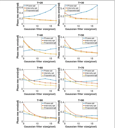
Results
The effectiveness of the proposed method is verified through simulation. In practice, the measurement quality is ultimately determined by phase quality of the binary dithering fringes. The simulation is performed for fringe patterns with different defocusing levels to test the phase RMS error. Because (n + 2)-step phase-shifting is in-sensitive to the n order harmonics, ten-step phase-shifting technology is used as the reference. The sinusoidal pattern with the same period is used as the reference data to calculate the phase RMS error. The phase RMS error is calculated after applying different
sizes of Gaussian filter. In this paper, the Gaussian filter size of 5 × 5 is used to represent slightly defocused and 13 × 13 represents strongly defocused. We use Gaussian filter of sizes G= 5∼17 andσ=G/3 to simulate the de-focused projector. In this simulation, the phase is ob-tained by using a three-step phase-shifting algorithm
with equal phase shifts. The phase RMS error is calcu-lated by taking the difference between the phase ob-tained from the smoothed binary patterns and the phase obtained from the ideal sinusoidal fringe patterns. Figure3shows the phase RMS error comparison among the phase optimized fringes [18], intensity optimized
fringes [19] and the proposed fringes of whole-fringe optimization. The periodT ranges from 20 pixels to 90 pixels (T= 20,30...90). When the period is small the intensity-based optimization has less phase RMS error than phase-based optimization, and the proposed optimization has the same tendency with intensity-based optimization but it is superior to the intensity-based optimization with different Gaussian filter sizes. When the period is increased, the phase RMS error has little change. It shows the optimized dithering fringe pattern
can be used not only for small period but also for large period fringe pattern. Especially when the period is very large such as T= 90 pixels, the proposed optimization has the least phase RMS error compared with the other two methods. It shows that the proposed method in-herits the features of dithering fringe pattern and it has the advantage to be used for large range 3D shape meas-urement with wide fringe pattern.
By analyzing of the simulation, we can also find that when the projector is slightly defocused (Gaussian filter
Fig. 43D shape measurement system
size is 5 × 5), the phase-based optimization has the low-est phase RMS error while with the Gaussian filter size increasing, the quality of phase optimized fringes de-creases due to the sensitivity to the filter size. The phase error of the intensity-based optimization fringes and the proposed fringes decrease sharply as filter size increases, and they outperform the phase optimized fringes. Be-cause the proposed method focuses on the local struc-ture similarity, the proposed fringes have the same tendency with the intensity optimization fringes and it outperforms the intensity-based optimization fringes on phase quality with all filter sizes.
We also develop a 3D shape measurement system to verify the proposed method. As shown in Fig. 4, in this system, we utilize a DLP projector (Samsung SP-P310MEMX) and a digital CCD camera (Daheng MER-500-14U3M/C-L). The camera is attached with a 16 mm focal length lens (Computar M1614-MP) with an image resolution 1024 × 768. The projector has 800 × 600 reso-lution and 0.49–2.80 m projection distance.
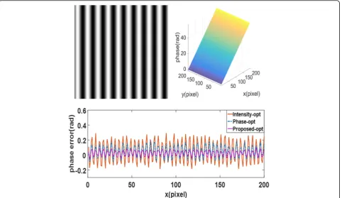
The first experiment is to reconstruct a flat white board with the intensity-based optimization fringes pat-tern, the phase-based optimization fringe pattern and the the patterns base on our method. The projector and
the camera are operated under exactly the same condi-tion during all experiments. The captured fringe patterns by the proposed method are shown in Fig. 5a and the projector is set to slightly defocused. Figure 5b shows the reconstruction result of the plane. And the phase errors of the reconstruction results with different methods are shown in Fig. 5c. Again, the proposed method generated the best results while the intensity-based optimization method performs worst.
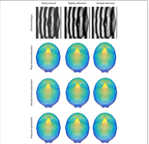
To verify the the robustness of the proposed fringe pattern under different defocusing levels and evaluate the measurement quality, a more complex 3D mask is measured. In practice, it is hard to give quantitative levels, so in this paper, the projector defocusing levels are set: nearly focused, slightly defocused and strongly defocused. Because dithering fringe pattern has the ad-vantage for large-range 3D shape measurement with wide stripes, in this measurement the periodT is set to 90 pixels. The measurement results are shown in Fig.6.
From the measurement results, we can find that when the projector is nearly focused, measured results of all the optimized binary fringes are strongly corrupted by noises but the phase-based optimization and the proposed optimization fringe pattern can get better re-sults with less noise. In order to compare the measure-ment result RMS error, we use the result from 9-step shifted fringe patterns as reference. The measurement results comparison under different projector defocusing levels are presented in Tables1, 2and3. When the pro-jector defocsing level increases, the phase error of all the optimization decreases in general and the phase error of intensity-based fringe and the proposed fringe are larger than phase-based optimization. The RMS of phase-opt, intensity-opt and the proposed-opt are 0.75 mm, 0.62 mm and 0.43 mm, respectively.
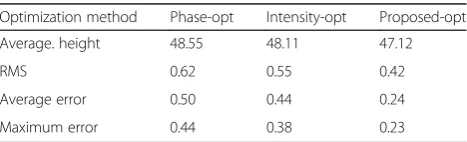
With the defocusing levels increasing, when the projector is slightly defocused and strongly defocused, the dithering binary pattern will get smoother and the proposed method will get more accurate measurement results than the phase-based and intensity-based optimization methods. Under slightly defocused, RMS of phase-opt, intensity-opt and the proposed-intensity-opt are 0.62 mm, 0.55 mm and 0.42 mm, respectively and under strongly defocused, they are 0.42 mm, 0.42 mm and 0.38 mm. From the measurement results and error comparison, we can find that the phase-based method and proposed method perform better than the intensity-based method under the nearly focused for optimization, while the proposed method and intensity-based method steadily improves the accuracy with increasing amount of defocusing. Especially under the slightly de-focused and strongly dede-focused, they are superior to the phase-based method. By comparison and analysis, because we combine the global similarity and local similarity, the proposed optimization fringe pattern has better measurement quality and less RMS error from nearly focused to strongly defocused. This experi-ment also conforms with our simulation results. It demonstrates that the proposed method can achieve high quality fringe patterns when the projector is at different amounts of defocusing and the proposed method outperforms the phase-based method and the intensity-based method.
Conclusion
Recently the optimization methods just qualify the glo-bal similarity of the pattern while the gloglo-bal optimization methods ignore the influences of local structure. In order to get high-quality binary dithered patterns, we propose a dithering optimization techniques by combin-ing global similarity and local structure similarity. Both simulation and experimental results have demonstrate that the proposed algorithm can achieve binary fringe pattern with high measurement quality and it is robust to the amounts of defocusing.
Abbreviations
3D:Three-dimensional; i-opt: Intensity-based optimization; p-opt: Phase-based optimization
Table 1The measurement comparison under nearly focused.
(Units:mm)
Optimization method Phase-opt Intensity-opt Proposed-opt
Average. height 48.88 49.16 47.33
RMS 0.62 0.75 0.43
Average error 0.54 0.55 0.33
Maximum error 0.44 0.49 0.25
Table 2The measurement comparison under slightly defocused.
(Units:mm)
Optimization method Phase-opt Intensity-opt Proposed-opt
Average. height 48.55 48.11 47.12
RMS 0.62 0.55 0.42
Average error 0.50 0.44 0.24
Maximum error 0.44 0.38 0.23
Table 3The measurement comparison under strongly defocused.
(Units:mm)
Optimization method Phase-opt Intensity-opt Proposed-opt
Average. height 47.26 47.93 47.01
RMS 0.42 0.42 0.38
Average error 0.40 0.37 0.24
Acknowledgements
This work was supported by the Fundamental Research Funds for the Central Universities (N150403009) and the Fundamental Research Funds for the Central Universities (N162610004).
Funding
Faculty of Robot and Engineering of Northeastern University, Shenyang, China provides the funding for this research.
Availability of data and materials
Details data has been provided in this paper.
Authors’contributions
All authors contribute equally in all the sections of this work. All authors read and approved the final manuscript.
Authors’information
Feng Lu, a doctor of Faculty of Robot Science and Engineering, Northeastern University, Shenyang, China. His interest includes Structured light, Robot and image processing.
Competing interests
The authors declare that they have no competing interests.
Publisher’s Note
Springer Nature remains neutral with regard to jurisdictional claims in published maps and institutional affiliations.
Author details
1Faculty of Robot Science and Engineering, Northeastern University,
Shenyang, China.2Ophthalmology, General Hospital of Shenyang Military Region, Shenyang, China.
Received: 2 January 2018 Accepted: 9 April 2018
References
1. Niu, Z., Gao, N., Zhang, Z., et al.: 3D shape measurement of discontinuous specular objects based on advanced PMD with bi-telecentric lens. Opt. Express. 26(2), 1615 (2018)
2. Hyun, J.S., Zhang, S.: Superfast 3D absolute shape measurement using five binary patterns. Opt. Lasers Eng. 90, 217–224 (2017)
3. Ayubi, G.A., Ayubi, J.A., Martino, J.M.D., Ferrari, J.A.: Pulse-width modulation in defocused 3-d fringe projection. Opt. Lett. 35, 3682–3684 (2010) 4. Zuo, C., Chen, Q., Feng, S., Feng, F., Gu, G., Sui, X.: Optimized pulse width
modulation pattern strategy for three-dimensional profilometry with projector defocusing. Appl. Opt. 51(19), 4477–4490 (2012) 5. Yang, Z., Xiong, Z., Zhang, Y., et al.: Depth Acquisition from Density
Modulated Binary Patterns[J]. 9(4), 25–32 (2013)
6. Lohry, W., Zhang, S.: 3d shape measurement with 2d area modulated binary patterns. Opt. Laser Eng. 50(7), 917–921 (2012)
7. Wang, Y., Zhang, S.: Comparison of the squared binary, sinusoidal pulse width modulation, and optimal pulse width modulation methods for three-dimensional shape measurement with projector defocusing. Appl. Opt. 51, 861–872 (2012)
8. Wang, Y., Jiang, C., Zhang, S.: Double-pattern triangular pulse width modulation technique for high-accuracy high-speed 3D shape measurement. Opt. Express. 25(24), 30177 (2017)
9. Xian, T., Su, X.: Area modulation grating for sinusoidal structure illumination on phase-measuring profilometry. Appl. Opt. 40, 1201–1206 (2001) 10. Lohry, W., Zhang, S.: Fourier transform profilometry using a binary area
modulation technique[J]. Opt. Eng. 51(11), 3602 (2012).
11. Jiang, H., Zhao, H., Diao, X., et al.: High-speed triangular pattern phase-shifting 3D measurement based on the motion blur method. Opt. Express. 25(8), 9171 (2017)
12. Zi-Xin, X.U., Chan, Y.H.: Removing harmonic distortion of measurements of a defocusing three-step phase-shifting digital fringe projection system. Opt. Lasers Eng. 90, 139–145 (2017)
13. Wang, Y.J., Zhang, S.: Three-dimensional shape measurement with binary dithered patterns. Appl. Opt. 51, 6631–6636 (2012)
14. Li, B.W., Wang, Y.J., Dai, J.F., Lohry, W., Zhang, S.: Some recent advances on superfast 3D shape measurement with digital binary defocusing techniques. Opt. Lasers Eng. 54, 236–246 (2014)
15. Lohry, W., Zhang, S.: Genetic method to optimize binary dithering technique for high-quality fringe generation. Opt. Lett. 38, 540–542 (2013) 16. Karpinsky, N., Wang, Y., Zhang, S.: Three-bit representation of three-dimensional
range data. Appl. Opt. 52(11), 2286 (2013)
17. Chatterjee, A., Tudu, B., Paul, K.C.: Binary genetic algorithm-based pattern LUT for grayscale digital half-toning. Signal. Image Video Process. 7(2), 377–388 (2013)
18. Dai, J., Li, B., Zhang, S.: High-quality fringe pattern generation using binary pattern optimization through symmetry and periodicity. Opt. Lasers Eng. 52(1), 195–200 (2014)
19. Dai, J., Li, B., Zhang, S.: Intensity-optimized dithering technique for three-dimensional shape measurement with projector defocusing. Opt. Lasers Eng. 53, 79–85 (2014)
20. Dai, J., Zhang, S.: Phase-optimized dithering technique for high-quality 3D shape measurement. Opt. Lasers Eng. 51, 790–795 (2013)
21. Lau, D.L., Arce, G.R.: Modern digital halftoning, 2rd ed. CRC Press, U.S.A (2008)
22. White, T.E., Rojas, B., Mappes, J., et al.: Colour and luminance contrasts predict the human detection of natural stimuli in complex visual environments. Biol. Lett. 13(9), (2017)