www.adv-radio-sci.net/8/27/2010/ doi:10.5194/ars-8-27-2010
© Author(s) 2010. CC Attribution 3.0 License.
Radio Science
Leaky wave antenna with amplitude controlled beam steering based
on composite right/left-handed transmission lines
M. A. Ebersp¨acher and T. F. Eibert
Lehrstuhl f¨ur Hochfrequenztechnik, Technische Universit¨at M¨unchen, Germany
Abstract. An antenna comprising two different compos-ite right/left-handed transmission line structures is proposed which enables easy beam steering at an operation frequency of 10 GHz. The composite right/left-handed transmission lines are based on planar, periodically arranged via free unit cells, implemented in microstrip technology. Both transmis-sion lines exhibit the infinite wavelength phenomenon which occurs at 9.72 GHz and 9.89 GHz, respectively. Thus, op-erating the different leaky wave structures at 10 GHz, radia-tion with azimuth angles of±8◦and±17◦can be achieved depending on the selected input port. In order to obtain a tunable main beam direction, the radiation patterns of both structures are superimposed by feeding them simultaneously. The influence of each guiding structure, and hence the direc-tion of the main beam, can be controlled via the feeding am-plitude. As a result of this, the beam can be steered between ±17◦with a gain of up to 10 dBi. The guiding structures are arranged in parallel with a clearance ofa=12.2 mm which is less than half of the wavelength in free space. This allows in a further step the attachment of additional guiding structures in order to increase the tunable angle range or creating an antenna array with a small beamwidth in the elevation plane without the occurrence of grating lobes. An antenna proto-type was fabricated and validated by measurements.
1 Introduction
Since the advent of automotive radar systems, highly direc-tive antennas supporting easy beam steering have received considerable attention. As shown in Balanis (2005), the beamwidth of an antenna becomes smaller when its aperture is increased. Thus, realising a small beamwidth requires a
Correspondence to: M. Ebersp¨acher
(mark.eberspaecher@tum.de)
sufficiently large aperture. Travelling wave antennas are at-tractive candidates for this type of application due to the fact, that their aperture sizes do not adhere with the operation fre-quency, and hence the aperture can be chosen almost arbitrar-ily. The mapping between frequency and radiation direction of the antenna can be controlled during the design process by dispersion engineering (Walter, 1965). However, the main beam direction of a leaky wave antenna is tightly coupled to the operation frequency and cannot be changed dynami-cally. Thus, many research efforts have been done and versa-tile concepts have been presented to allow beam steering at a constant frequency, for example with a rotating dielectric grating structure as in Schneider and Wenger (2003), with a movable dielectric slab as in Matsuzawa et al. (2006), or by using lens antennas as in Binzer et al. (2007). All these presented structures are proven to work well, however, their realisation and production is very costly.
2 Theory
2.1 Principle of leakage radiation
A leaky wave is a travelling wave which progressively leaks out power as it propagates along a waveguiding structure (Caloz and Itoh, 2006). Consequently, a structure supporting one or more leaky waves is referred to as leaky wave struc-ture. In the following, a planar waveguide located in thexy -pane is considered. The waveguide supports an electromag-netic wave travelling along the structure in thex-direction. By suppressing the time dependency, this wave can be de-scribed asψ (x)=ψ0e−γ x, whereγ=α+jβ represents its
complex propagation constant. The field above the guiding structure which is excited by the travelling wave can be writ-ten as
p
b
b
b
b
CL LR
LL CR
b
c bc
b
c bc
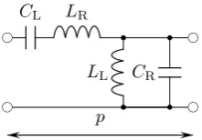
Fig. 1. Equivalent circuit of a CRLH TL unit cell with series
impedance Z=jωLR+jωC1
L and the parallel admittance Y =
jωCR+jωL1L.
In order to fulfill Maxwell’s equations, the wavenumber in z-direction is given as
kz=
q
k02−(β−jα)2, (2)
wherek0=ω/c is the free space wavenumber. If we consider
a lossless antenna with relatively small leakage, α can be neglected and the wavenumber simplifies tokz=
q
k20−β2.
Depending onβ, this leads either to a purely imaginarykz
or a purely realkz. Accordingly, the first case represents an
evanescent wave exponentially decaying whereas the latter stands for leakage radiation.
The main beam direction of this leakage radiation can be calculated as shown in Walter (1965) according to
2MB=arcsin
β(ω) k0
. (3)
Analysing the argument of the angular function yields that a real angle can only be found for|β(ω)| ≤k0. This accords
exactly to the prerequisites in Eq. (2) for a purely real propa-gation constantkz.
The relationship between the beamwidth 2BW and the
aperture lengthLof the leaky wave antenna is given in John-son (1993) by
2BW≈
1 (L/λ0)cos2MB
. (4)
For a given value ofα, the antenna lengthLis usually cho-sen so that approximately 90% of the power is radiated. As expected, the beamwidth becomes smaller for a longer aper-ture.
2.2 Artificial transmission line theory
In order to design leaky wave antennas with predefined be-haviour, guiding structures with certain dispersion character-istics are required. A very powerful approach to accomplish this are periodic structures. This type of structures are com-posed of periodically arranged small sections, which can be considered as unit cells. It is shown that the analysis of the whole structure can be restricted to the analysis of one unit cell (Pozar, 2005). Hence, in the ideal case also the design
process of a guiding structure is reduced to the design effort of a single cell. The dispersion behaviour of such a guiding structure is given by
(α+jβ)p=arccoshA+D
2 , (5)
wherepstands for the physical length of the unit cell and the parametersAandD are its elements of the ABCD-Matrix representation. Since the result of the arccosh-function is ambiguous, the phase constant has multiple solutionsβnp=
β0p+2π np withn=0,±1,±2,±3,.... Besides the
funda-mental modeβ0, an infinite number of so-called space
har-monics are obtained. In general, a structure can be designed in such a way that either radiation occurs at the fundamental mode or at any arbitrarily chosen space harmonic as long as Eq. (3) leads to a real angle2MB. However, as it is
men-tioned in Paulotto et al. (2008) radiation at broadside using space harmonics can be disturbed due to coupling effects of a pair of these harmonics resulting in an open stop band. This problem can be overcome by radiating only with the fundamental mode. Consequently, β0 is forced to be zero
to achieve broadside radiation at a certain frequencyω6=0, which can be realised by using composite right/left-handed (CRLH) transmission lines.
As shown in Fig. 1, the CRLH-unit cell is composed of a series and a parallel resonant circuit with the resonant fre-quenciesωs andωp, respectively. In both resonant circuits
the elements denoted with index Lare accountable for the left-handed behaviour of the arrangement. On the other hand, components with index R make the unit cell to behave as right-handed. According to the equivalent circuit of a con-ventional transmission line, the right-handed contributions can be implemented either as lumped elements or as sections of transmission lines. Additionally, the occurring parasitics can be included in these elements.
Calculating the corresponding ABCD-Matrix elements of the circuit in Fig. 1, inserting them in Eq. (5), and per-forming a taylor series expansion yields jβ=
√
Y Z p . It is shown in Caloz and Itoh (2006), thatβ= <{β}, ifωs=ωp,
and hence no stop band occurs. This case is referred to as the balanced case in which the phase constant is written as jβ= j
p
ω√LRCR−ω√C1
LLL
. Obviously, a given value of the phase constant at a certain frequency can be realised by choosing the appropriate network elementsLR,CR,LL and
LL. Thus, it is possible to create a leaky wave structure
pos-sessing a certain main beam direction at a given frequency. The counterpart of the characteristic impedance of a ho-mogeneous transmission line is the Bloch impedance of a periodic artificial structure. In contrast to the characteris-tic impedance, the latter is usually given at the terminals of the unit cell only. According to Pozar (2005), the Bloch impedance can be determined based on the ABCD-Matrix elements as
ZL=
r
Z
x
y
z
a
-ΘMB2
ΘMB2
ΘMB1
-ΘMB1
Fig. 2. Arrangement of two times two identical leaky wave
struc-tures. Excitation according to the red solid and dashed arrow leads
to main beam direction2MB1 and−2MB1, respectively.
Excita-tion according to the blue solid and dashed arrow leads to main
beam direction2MB2and−2MB2, respectively.
Applying Eq. (6) to the circuit in Fig. 1 results in the fre-quency independent Bloch impedanceZL=
q
LL
CL= q
LR
CR.
2.3 Concept of beam steering
Naturally, the main beam direction of a leaky wave antenna can be steered by changing its operation frequency. How-ever, a concept allowing different main beam directions at a constant frequency is investigated in this work.
To clarify the basic idea, let us consider a leaky wave struc-ture with two ports located at their opposite ends. The ports are referred to as port 1 and port 2, respectively. Operating the structure at the frequencyf0=ω0/2π6=0 at port 1, a
leakage mode is excited which propagates along the struc-ture to port 2 at which it is supposed to be absorbed. Thus, radiation occurs with an azimuth main beam2MB1according
to Eq. (3) and the propagation constant of the excited mode. The structure can be designed in such a way that this angle 2MB16=0 at the frequencyf0.
If the driven port and the terminated port are interchanged, the phase constant will be negative with respect to port 1 and hence, radiation with the main beam direction−2MB1 will
occur. As it is seen in Eq. (4), the beamwidth2BW1 of the
antenna in the azimuth plane is determined by the aperture lengthL. Thus, the beamwidth can be manipulated by the amount of cascaded unit cells along thex-axis.
Further main beam angles are achievable by adding other leaky wave structures in parallel which possess the angles ±2MBn. This can be done any number of times if the
beamwidth in the elevation (yz-) plane can be broad. How-ever, the requirement of a small beamwidth in this plane lim-its this approach, since leaky wave structures exhibiting the same azimuth angle must be repeated periodically. Figure 2 shows such an arrangement of two times two leaky wave
Lcap
Lind
0.3 0.3
0.3
2.1
0.9 2.2 0.9
0.3 0.3
ind
cap
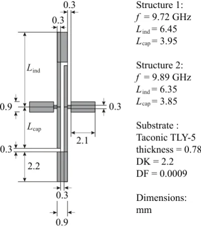
Structure 1:
f = 9.72 GHz
L = 6.45
L = 3.95
Structure 2:
f = 9.89 GHz
L = 6.35
L = 3.85
Substrate : Taconic TLY-5 thickness = 0.78 DK = 2.2 DF = 0.0009
Dimensions: mm
ind
cap
Fig. 3. Layout of the two realised unit cells.
structures. Structures possessing the same main beam direc-tion are marked with arrows of the same colour. The distance between identical antennas is a. In order to avoid grating lobes in theyz-plane, a has to be smaller thanλ0 for
radi-ation in the upper hemisphere only. This limitradi-ation makes the design process troublesome, since reducing the clearance leads to increased mutual coupling. The increase of the cou-pling effects can grow up to such an extent that the structure becomes inoperative.
According to the antenna depicted in Fig. 2, there are four different main beam directions possible, which can be chosen via the corresponding feeding. An excitation of the antenna according to the red solid and dashed arrows leads to radi-ation into the direction of2MB1 and−2MB1, respectively.
The angles2MB2 and−2MB2 can be adjusted by feeding
according to the blue solid and dashed arrows, respectively. Furthermore, the radiation patterns of two structures can be superimposed by feeding them simultaneously in order to gain additional main beam directions. The influence of each guiding structure, and hence the direction of the main beam, can be controlled via the feeding amplitude. To ensure that each combination leads to only one main beam, the particular patterns have to fulfill
2MB1+2BW1/2≥2MB2−2BW2 (7)
with2MB1≤2MB2.
3 Realisation
b b b b
b b b b
I1 LR/2 CL LR/2
2LL CR
2 2LL
CR 2
b
c
b
c
b
c
b
c
U1 U2
Fig. 4. Simplified equivalent circuit model of the realised unit cell
with neglected losses.
9.0 9.5 10.0 10.5 11.0 11.5 12.0
-0.8 -0.6 -0.4 -0.2 0 0.2 0.4 0.6 0.8 1.0
f
GHz
βp π
−k0p k0p
Fig. 5. Dispersion diagram of the unit cells with the transition
fre-quenciesf1=9.72 GHz (red line) andf2=9.89 GHz (blue line).
At 10 GHz the unit cells exhibit a phase constant ofβ1=0.098πp
andβ2=0.038πp, respectively.
frequency of 10 GHz the main beam directions 2MB1 and
2MB2, respectively. In order to allow the extension of the
aperture iny-direction subsequently, the distance between adjacent structures should be less thanλ0/2. Furthermore,
an easy to fabricate design is wanted which can be produced using a standard photolithography process.
The unit cell presented in Ebersp¨acher et al. (2009) is eas-ily realisable and needs neither an interlayer connection nor a multilayer fabrication process. Hence, it can be produced in an entirely printed circuit technology. Consequently, the con-cept of this unit cell is taken as a basis for this antenna design. However, it cannot be implemented directly, since strong mu-tual coupling between adjacent leaky wave structures occurs. Therefore, the unit cell must be narrowed iny-direction with-out changing the electromagnetic behaviour. This means that the open ended inductive stubs must be shortened while the electrical length must be unchanged. This can be achieved by introducing impedance steps along the stub. Beginning at the open end, a stepwise change of the characteristic impedance from a low to a high level is required. In microstrip technol-ogy, this is easily achieved by a step in the width of the line. The resulting design is shown in Fig. 3.
In the next step, the unit cells were balanced upon the transition frequencies 9.72 GHz and 9.89 GHz. According to
1 2
3 4
Fig. 6. Fabricated leaky wave structures. The numbers are
indicat-ing the ports.
-40 -30 -20 -10 0
9 10 11 12
M
a
g
ni
tude
/
dB
f
GHz
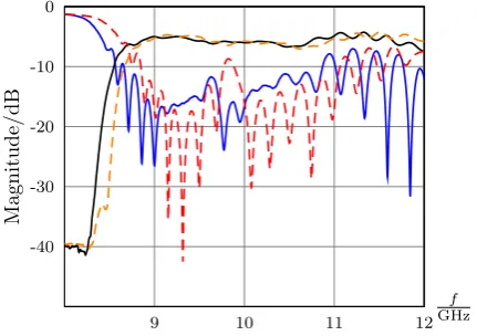
Fig. 7. MeasuredS-parameters of the leaky wave structures: S11
blue line,S21black line,S33red dashed line andS43orange dashed
line.
the dispersion diagram seen in Fig. 5, one obtains the phase constants ofβ1(2π10 GHz)=0.098πp andβ2(2π10 GHz)=
0.038πp, respectively. Employing Eq. (3), this leads theoret-ically to the main beam directions2MB1=15◦and2MB2=
5.8◦. Balancing a unit cell consisting of discrete elements can be done easily by choosing the appropriate values. How-ever, the proposed cell requires a more sophisticated balanc-ing procedure. Therefore, information are required which describe whether the unit cell is balanced or not. Further-more, it is important to know, which resonant circuit should be tuned. These information are provided by the Z and Y matrix elements obtained by the numerical computation soft-ware CST Microwave Studio (CST).
During the balancing process of the structure losses are not considered. According to the resulting simplified equivalent circuit model, seen in Fig. 4, the elementZ21 can be
calcu-lated analytically. Per definition Z21=UI12
I2=0
. From this follows that neither of the series inductances must be taken into account. Thus, this impedance reads
Z21=
jω34L2LCL (1−ω2L
LCR)(1−ω2LLCR−ω24CLLL)
. (8)
Searching for roots of the denominator gives ωfp=
q
1
-50 -40 -30 -20 -10 0
9 10 11 12
M
a
g
ni
tude
/
dB
f
GHz
Fig. 8. MeasuredS-parameters of the leaky wave structures: S31
blue line,S41black line,S32red dashed line andS42orange dashed
line.
5 10
-5
-10
-15
-75 -60 -45 -30 -15 0 15 30 45 60 75 90
Gain dBi
θ
deg
Fig. 9. Radiation pattern in thexz-plane (x-direction polarised). Measurement and simulation results are drawn in solid lines and dashed lines, respectively. Excitation at port 1 (blue line) and at port 2 (red line).
and ωfpres=
q
1
LLCR.
SinceCL>0, it is found thatωfp< ωfpres. The numerator
is unequal to zero at both frequencies which leads to two maxima of|Z21|. The position of the peak occurring at the
higher frequency identifies the parallel resonant frequency. Determining the series resonant frequency can be done based onY11. With the prerequisites that the parallel resonant
frequency is tuned correctly, its conductance is insignificant around this frequency. Thus, the admittance matrix element simplifies to
Y11=
I1
U1
U2=0
≈ jωLR 1−ω2L
RCL
. (9)
Only one maxima can be found for|Y11|which identifies
ex-actly the series resonant frequencyωf sres= q
1
LRCL.
Follow-5 10
-5
-10
-15
-75 -60 -45 -30 -15 0 15 30 45 60 75 90
Gain dBi
θ
deg
Fig. 10. Radiation pattern in thexz-plane (x-direction polarised). Measurement and simulation results are drawn in solid lines and dashed lines, respectively. Excitation at port 2 (blue line) and at port 4 (red line).
5 10
-5
-10
-15
-75 -60 -45 -30 -15 0 15 30 45 60 75 90
Gain dBi
θ
deg
Fig. 11. Radiation pattern in thexz-plane (x-direction polarised). Measurement and simulation results are drawn in solid lines and dashed lines, respectively. Excitation at port 1+3 (blue line) and at port 2+4 (red line).
ing these steps, both unit cells were balanced and tuned cor-rectly to the desired frequencies. Their exact dimensions are shown in Fig. 3.
It should be mentioned, that due to mutual coupling the be-haviour of a cascaded unit cell changes and detuning occurs. Thus, it is advisable to determine the elementsY11 andZ21
out of a cascaded arrangement by performing a deembedding process.
4 Results
5 10
-5
-10
-15
-75 -60 -45 -30 -15 0 15 30 45 60 75 90
Gain dBi
θ
deg
Fig. 12. Measured radiation pattern in thexz-plane (x-direction po-larised). Excitation and colors are related as follows: Port 1 black, port 2 red, port 3 yellow, port 4 blue, port 1+3 gray dashed, port 2+4 green dotted, port 3+4 orange. Detailed pattern information are given in Table 1.
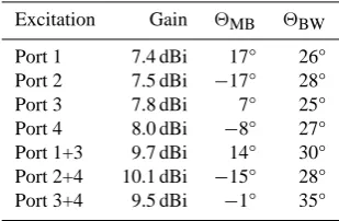
Table 1. Measured radiation pattern characteristics of the realised
antenna.
Excitation Gain 2MB 2BW
Port 1 7.4 dBi 17° 26°
Port 2 7.5 dBi −17° 28°
Port 3 7.8 dBi 7° 25°
Port 4 8.0 dBi −8° 27°
Port 1+3 9.7 dBi 14° 30°
Port 2+4 10.1 dBi −15° 28°
Port 3+4 9.5 dBi −1° 35°
shown in Fig. 8, this analysis yields an attenuation greater than 15 dB between neighbouring structures over a broad frequency range. The dispersion diagram obtained by sim-ulation and the measured radiation patterns are depicted in Figs. 5, 9–12. Details of the achieved results are provided in Table 1. All parameters possess a good agreement with the analytical results from Eqs. (3) and (4). As expected, the gain increases when both structures are driven simultane-ously, since the aperture iny-direction is enlarged. Conse-quently, the beamwidth in theyz-plane becomes smaller and gain enhancement takes place.
5 Conclusions
A beam steering concept was presented, which is based on two leaky wave structures with different main beam direc-tions. The structures are realised as composite right/left-handed transmission lines with different transition frequen-cies. Thus, the main beam can be switched according to the chosen feeding port or steered by superimposing the different radiation patterns. The presented antenna possesses a scan angle range of−17◦≤0≤17◦with a gain of up to 10 dBi at the operation frequency of 10 GHz.
References
Balanis, C. A.: Antenna theory – analysis and design, John Wiley & Sons, 3rd edn., 2005.
Binzer, T., Klar, M., and Groß, V.: Development of 77 GHz Radar Lens Antennas for Automotive Applications Based on Given Requirements, 2nd International ITG Conference on Antennas, 2007.
Caloz, C. and Itoh, T.: Electromagnetic Metamaterials, John Wiley & Sons, 2006.
CST Computer Simulation Technology, http://www.cst.com/, ac-cess: 31 March 2010.
Ebersp¨acher, M. A., Eccleston, K., and Eibert, T. F.: Realization of Via-free Microstrip Composite Right/Left-Handed Transmis-sion Lines, Proceedings of the German Microwave Conference GeMiC 2009, 2009.
Johnson, R.: Antenna Engineering Handbook, chap. Leaky-Wave Antennas, McGraw Hill, 3rd edn., 1993.
Matsuzawa, S., Sato, K., Inoue, Y., and Nomura, T.: W-Band Steer-able Composite Right/Left-Handed Leaky Wave Antenna for Au-tomotive Applications, IEICE TRANSACTIONS on Electronics, 2006.
Paulotto, S., Baccarelli, P., Frezza, F., and Jackson, D. R.: Full-Wave Modal Dispersion Analysis and Broadside Optimization for a Class of Microstrip CRLH Leaky-Wave Antennas, IEEE Transaction on Microwave theory and techniques, 2008. Pozar, D. M.: Microwave Engineering, John Wiley & Sons, 3rd
edn., 2005.
Schneider, R. and Wenger, J.: High resolution radar for automobile applications, Adv. Radio Sci., 1, 105–111, 2003,
http://www.adv-radio-sci.net/1/105/2003/.