1
EXPERIMENT N0:
06
AIM:TO DESIGN UMTS NETWORK USING OPNET MODELER
APPARATUS: OPNET MODELER 14.0
THEORY:Universal Mobile Telecommunications System (UMTS) is a Third Generation (3G) wireless protocol that is part of the International Telecommunications Union's IMT-2000 vision of a global family of 3G mobile communications systems. UMTS is expected to deliver low-cost, high-capacity mobile communications, offering data rates up to 2-Mbps. The UMTS model suite allows you to model UMTS networks to evaluate end-to-end service quality, throughput, drop rate, end-to-end delay, and delay jitter through the radio access network and core packet network. It can also be used to evaluate the feasibility of offering a mix of service classes given quality of service requirements. This model is available as part of the specialized model library.
The UMTS model of the packet wireless network is based on 3rd Generation Partnership Project (3GPP) Release 1999 standards. The network architecture of this release is divided into the radio access network (RAN) and the core network as shown in figure. The UMTS module models the UMTS RAN and the UMTS functionality of the core network (see highlighted elements in figure). The radio access network for UMTS contains the User Equipment (UE), which includes the Terminal Equipment (TE) and Mobile Terminal (MT), and the UMTS Terrestrial Radio Access Network (UTRAN), which includes the Node-B and Radio Network Controller (RNC).
UMTS uses Wideband Code Division Multiple Access (W-CDMA) access scheme. This version of W-CDMA uses direct spread with a chip rate of 3.84 Mcps and a nominal bandwidth of 5 MHz. The model supports one of W-CDMA's two duplex modes: Frequency Division Duplex (FDD). Time Division Duplex (TDD) is not supported. In FDD mode, uplink and downlink transmissions use different frequency bands. The radio frame has a length of 10 ms and is divided into 15 slots. Spreading factors vary from 256 to 4 for an FDD uplink and from 512 to 4 for an FDD downlink. With these spreading factors, data rates of up to 2 Mbps are attainable.
2 The circuit switched (CS) core network, which is not currently modeled, includes the mobile switching center/visitor location register (MSC/VLR). The MSC/VLR is used in the packet domain architecture to efficiently coordinate PS and CS services and functionality. The Home Location Register (HLR) contains GSM and UMTS subscriber information. The Charging Gateway Functionality (CGF) collects charging records from the SGSN(s) and GGSN. The Equipment Identity Register (EIR) stores information about user equipment identity. The HLR, CGF, and EIR are included in this description for completeness, but are not currently modeled.
Creating a UMTS Network Topology
3
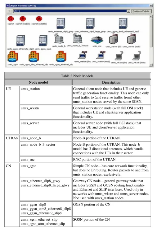
Table 2 Node Models
Node model Description
UE umts_station General client node that includes UE and generic
traffic generation functionality. This node can only send traffic to (and receive traffic from) other umts_station nodes served by the same SGSN.
umts_wkstn General workstation node (with full OSI stack)
that includes UE and client/server application functionality.
umts_server General server node (with full OSI stack) that
includes UE and client/server application functionality.
UTRAN umts_node_b Node-B portion of the UTRAN.
umts_node_b_3_sector Node-B portion of the UTRAN. This node_b
model has 3 directional antennas, which handle connections with the UEs in their sector.
umts_rnc RNC portion of the UTRAN.
CN umts_sgsn Simple CN node—has core network functionality,
but does no IP routing. Routes packets to and from umts_station nodes, exclusively.
umts_ethernet_slip8_gtwy umts_ethernet_slip8_large_gtwy
Gateway CN node—general gateway node that includes SGSN and GGSN routing functionality and Ethernet and SLIP interfaces. Used only in networks with umts_wkstn and umts_server nodes. Not used with umts_station nodes.
umts_ggsn_slip8
umts_ggsn_atm8_ethernet8_slip8 umts_ggsn_ethernet2_slip8
GGSN portion of the CN
umts_sgsn_ethernet_slip umts_sgsn_atm_ethernet_slip
4
Supported Configurations
You can configure your UMTS network model to use either of the following configurations:
UMTS workstation nodes routing application traffic (e-mail, ftp,...) through one or more CN nodes to other UMTS workstation or server nodes, or to workstations and servers running over other technologies, such as Ethernet or WLAN.
UMTS station nodes sending generic data traffic to other UMTS station nodes though a single or multiple SGSN nodes.
You cannot send application traffic to a UMTS station node, nor can you send traffic generated by a station node to a UMTS workstation or server node. When using the UMTS workstation nodes, use the application models to generate traffic as you would for any workstation node. See the application model documentation for additional information on configuring application traffic.
Using the station and SGSN nodes allow you to configure a traffic generation pattern that is not application-based. This avoids the need to use the application models when you are not interested in application-specific performance in the UMTS network. Consider using the station nodes and SGSN nodes when the following apply:
You want to model raw traffic data within the UMTS network.
You are not interested in the external IP network.
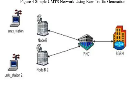
5 The following diagrams illustrate the supported types of UMTS network
configurations:
Figure3: Simple UMTS Network Using Application Traffic
6
Model Architecture
The GPRS network architecture is shown in Figure 5. This section describes the nodes shown in Figure 5, including their process and node models.
Figure5: UMTS Network Architecture
When a user powers-on, the model assumes that synchronization and a PS signaling connection are established. This PS signaling connection is kept for the entire simulation. Because of this, when a user powers-on it can immediately do a UMTS GPRS attach with the SGSN(s) to access to GPRS services.
Packets are queued when they are received from higher layers. Since each user supports four QoS profiles, the traffic is queued on one of four QoS queues. If no PDP context has been activated for that QoS profile, an Activate PDP Context Request is sent to the SGSN(s). This PDP context activation message includes the QoS requested. The model assumes that the SGSN(s), after consulting the RNC, either grants the QoS requested by the user in its entirety or rejects it. No negotiation by the SGSN/GGSN or RNC of the requested QoS is done at this stage.
7 On receipt of the Radio Bearer Setup request, the UE sets up the channel as specified in the request and send a Radio Bearer Complete to the RNC. On receipt of the Radio Bearer Complete, the RNC sends a RAB Assignment Response, which includes the granted QoS, to the SGSN/GGSN. The SGSN(s) then sends the Activate PDP Context Accept message, which also includes the granted QoS.
The UE can send packets to the destination on receipt of the Activate PDP Context Accept message from the SGSN(s). Before reaching their destination, these packets are first tunneled through serving the RNC and SGSN/GGSN, then routed through the IP cloud. If the destination network is also a UMTS network, then they are finally queued at the destination SGSN/GGSN node. Once a channel is set up at the destination, the packets are forwarded to the destination UE.