Patron: Her Majesty The Queen Rothamsted Research Harpenden, Herts, AL5 2JQ
Telephone: +44 (0)1582 763133 Web: http://www.rothamsted.ac.uk/
Rothamsted Research is a Company Limited by Guarantee Registered Office: as above. Registered in England No. 2393175. Registered Charity No. 802038. VAT No. 197 4201 51. Founded in 1843 by John Bennet Lawes.
Rothamsted Repository Download
A - Papers appearing in refereed journals
Gower, J. C. and Preece, D. A. 1972. Generating successive incomplete
blocks with each pair of elements in at least one block. Journal Of
Combinatorial Theory Series A. 12 (1), pp. 81-97.
The publisher's version can be accessed at:
•
https://dx.doi.org/10.1016/0097-3165(72)90085-4
The output can be accessed at:
https://repository.rothamsted.ac.uk/item/8wv7q/generating-successive-incomplete-blocks-with-each-pair-of-elements-in-at-least-one-block
.
© Please contact [email protected] for copyright queries.
JOURNAL OF COMBINATORIAL THEORY (A) 12, 81-97 (1972)
Generating Successive incomplete Blocks with Each Pair of Elements in at Least One Block
J. C. GOWER AND D. A. PREECE
Rothamsted Experimental Station, Harpenden, Hertfordshire, England Communicated by J. M. Hammersley
Received September 9, 1969
This paper examines solutions to the following combinatorial problem: Produce an ordered set of blocks of M elements chosen from N such that (i) any pair of the N elements occurs together in at least one block, and (ii) the total number of element changes in forming each new block from the previous one is minimised. For certain values of N and M, the only known solutions have no known generalisation. However, several general algorithms are described that produce sets of blocks satisfying (i) and either satisfying or nearly satisfying (ii). Other, related, combinatorial problems are outlined; all are relevant to organizing a certain type of data in a computer.
BACKGROUND
This work arose from a problem of data organization within a computer. The results are, however, of general combinatorial interest.
Many statistical calculations begin by computing a symmetric matrix of coefficients from data arranged in a rectangular matrix X; for example X’X or XX’ may be required. More elaborate coefficients than sums of products exist, but the basic requirement is still that every cell of the symmetric matrix is computed from a pair of columns (or rows) of X. If only M columns (rows) out of a total of N are available at any one time, the order of the computations is important. Various criteria may be used to define an optimum order. Different criteria give rise to different combinatorial problems, some of which are discussed in this paper.
On a computer, the matrix X will probably be held on backing store such as magnetic tape or disc, with the elements stored successively by columns (i.e., the last value in the tist column of X will be followed by the first value in the second column, etc.). As transfer of data from backing store to a working store is slower than arithmetic operations, an algorithm might be required that makes as few transfers of columns as possible.
81
82 GOWER AND PREECE
But the computation of coefficients from sets of columns will usually be done by a subroutine, use of which can be time-consuming too. Thus we may wish to minimise not the number T of transfers of columns, but the number B of different sets of M columns that have to be set up, or a function of T and B. These problems are discussed below.
An important practical constraint on the order of transferring columns of X applies when the backing store is magnetic tape. Here, efficiency demands that the machinery should not have to wind unnecessarily through tape containing columns not required at the time. With machinery that can read tape either forwards or backwards, unproductive winding can be avoided if-as with Nelder’s algorithm described below-the next column to be transferred is always the next or previous one on the tape. With machines that can read only forwards, general conditions for efficient winding are difficult to state. These matters are not, however, considered further in this paper.
We have found few relevant publications. Jowett [3] and Hammersley [2] are concerned with using the fewest operations to compute a particular coefficient (“Sums of Squares and Products”) on hand-operated calculating machines. Their problem differs from ours because they can deal straight- forwardly only with M = 2; also they are concerned with certain checks (particularly sum checks) that are important with hand calculation, but unlikely to be useful on stored-program computers.
The many balanced incomplete block designs (see, for example, the tables given by Fisher and Yates [I]) provide poor solutions to the transfer problem. Except with the cyclic and near-cyclic designs, there is no simple algorithm for generating the elements of successive blocks. With the cyclic designs there must be A4 new transfers for every block, so that, when h (the number of times every pair of columns occurs) = 1, we have
T = K3/i31
x M = N(N - l)/(M - 1);this is about twice as many transfers as in the designs discussed below, but the number of blocks B = T/M is the smallest possible. T can be made smaller by reordering the cyclically generated blocks so that there are M transfers for the first block and M - 1 thereafter, whence
GENERATING SUCCESSIVE INCOMPLETE BLOCKS 83
1. INTRODUCTION
Nelder [4] posed his combinatorial problem as follows: Produce an ordered set of blocks of M elements chosen from N such that
(i) any pair of the N elements occurs together in at least one block, and
(ii) the total number of element changes (i.e., transfers of single elements) in forming each new block from the previous one is minimised.
A solution for N = 7, M = 3 is
@1@55@7777
@22@33@@@1 (1)
@@44@6666@
where the ten blocks run vertically from left to right, and changes are ringed. This solution can also be represented by the following triangular diagram:
I234 5 6 7
(2)
The numbers down the left side of the diagram and along the bottom denote the elements; the numbers in the body of the diagram denote the blocks in which the corresponding pairs of elements appear together for the first time. The triangular diagram (2) shows that condition (i) is satisfied by (1); condition (ii) is satisfied because only one element is transferred for each new block, and after transfer the new element appears for the first time with each of the other elements in the block.
In what follows, triangular diagrams, with one block number for each pair of elements, are used for solutions of Nelder’s and other problems. But such a diagram does not necessarily correspond to only one solution, and a block number in the body of a diagram need not indicate the first
84 GOWER AND PREECE
2. NELDER'S ALGORITHM AND THE MINIMUM NUMBER OF TRANSFERS OF SINGLE ELEMENTS
As is proved in Nelder’s paper, a lower bound to the minimum number of transfers of single elements is
Ii
max M+
w-i3 ,2N--
M-l
1 1
3
where [xl denotes the least integer >x. This bound cannot, however, always be attained.Nelder gave a very simple algorithm which is near-optimum in the sense that the total number, T, of transfers of single elements is never more than 20 per cent larger than the above lower bound. The algorithm gives T = lower bound when M = 2, and when N < 2M, M > 2.
For N = 9, M = 3 Nelder’s algorithm gives
1 7 6 5 4 3 5
2 8 4 6
3456789 5 6 7 (3)
(only the elements that change are shown)
which has the triangular diagram:
2
‘h
3 ’
4 2
HL
5 3 13
---T
6 4 14
7 5 I5 lb
8 6 12 II IO 9 9 7
12 3 4 56
Here T = 21, whereas the lower bound, which is attainable (see below), is 20. In general, for Nelder’s algorithm,
GENERATING SUCCESSIVE INCOMPLETE BLOCKS 85
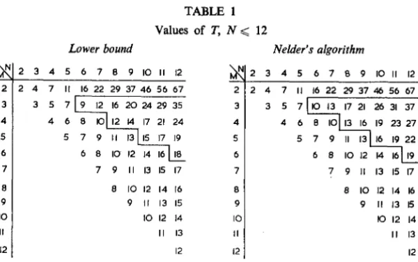
TABLE 1
Lower bound
Values of T, N < 12
Nelder’s algorithm
3 4 5 6 7 8 9 10 II 12 4 7 II 16 22 29 37 46 56 67
7 9 II I3 I5 I7
8 8 IO I2 I4 I6 9 9 II I3 I5
IO IO I2 14
II II I3
12 I2
2 3 4 5 6 7 8 9 IO II I2 2 2 4 7 II 16222937465667
3 4 5 6
7 7 9 II I3 I5 I7
8 8 IO 12 I4 I6 9 9 II 13 I5
IO IO I2 14
II II I3
12 I2
The outlined areas of the tables indicate the values of M and N for which Nelder’s algorithm gives more transfers than the lower bound.
3. NON-ISOMORPHISM OF SOLUTIONS
A representation such as (1) will be called a “design.” Two designs for a given set of values (N, M) will be said to be “non-isomorphic” (or “distinct,” or “structurally different”) if one cannot be changed into the other by any combination of (a) renaming the elements, (b) rearranging the rows, and (c) reading the design from right to left instead of from left to right.
It is easily seen that interchanging the 7th and 8th blocks of (1) produces a design that is still optimum, but not isomorphic to (1). A further, deeper type of non-isomorphism can be demonstrated by comparing (1) with the following, which is also optimum and for N = 7, M = 3:
1 5 6
2 3 6 7 (4)
3 4 1 3 2
Designs (1) and (4) can most readily be seen to be non-isomorphic by comparing the corresponding distributions of the number of times elements are transferred: writing ai for the number of elements transferred i times, we have
Solution a, a, a,
86 GOWER AND PREECE
and ai = 0 for i > 3. In general, the aj must, for an optimum design, satisfy
and
c aj = N, c iai = T, a, < M,
A G (N - 1)/W - 11,
(5)
where A is the greatest number of transfers of any element. The inequality for a, holds because elements transferred only once must occur together in some block. The inequality for A holds because at each transfer of an element it occurs with M - 1 out of the other N - 1 elements.
The existence of a set {ai> satisfying (5) does not necessarily imply the existence of a corresponding design. For N = 7, M = 3, the only possible sets {ai} are the two given above, but for N = 10, A4 = 3 there are 14 sets, as follows:
aI a2 a3 a4 Whether solution found
0 6 4 0 Yes
1 4 5 0 Yes
2 2 6 0 Yes
3 0 7 0 No
0 7 2 1 No
1 5 3 1 Yes
2 3 4 1 Yes
3 1 5 1 Yes
0 8 0 2 No
1 6 1 2 No
2 4 2 2 Yes
3 2 3 2 Yes
2 5 0 3 Proved impossible
3 3 1 3 Proved impossible
We define the complement, C, of a design D as the design such that (a) each block of C contains the elements absent from the corresponding block of D, and (b) if, in D, element i overwrites element j when block x + 1 is formed from block x, then, in C, j overwrites i at the corre- sponding place.
GENERATING SUCCFSSIVE INCOMPLETE BLOCKS 87
complementary optimum design has been found.) For example, the com- plementary designs
1 5 6 4 3 2 2 3 1 and 5 1 3 3 4 5 6 5 4
are non-isomorphic.
The complement of an optimum design with N > 2M will often be a poor design. For example, the complement of (4) has N = 7, M = 4,
T = 13, whereas an optimum design with N = 7, M = 4 has T = 10.
4. ON THE NUMBER OF BLOCKS IN A SOLUTION
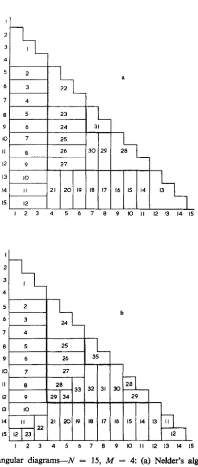
Different algorithms can use the same number of transfers of single elements, but dzyferent numbers of blocks. One of the most important ways in which this can happen is illustrated by comparing Nelder’s algorithm with a less simple variant, to be referred to as algorithm Nl. This can conveniently be done using the specimen values N = 15, M = 4.
The two triangular diagrams are Figures la and lb. With both proce- dures, the diagrams are divided into nested L-shaped bands, the L’s being “frayed” at their tips but otherwise of width M - 1. The bands are filled with block numbers successively, starting with the outermost. Once the second band is begun, it is filled by the same procedure as for the first, and so on. Any small region remaining after the innermost L has been filled is filled last. When deriving a design from Figure lb, care should be taken that element 4 in block 21 is not overwritten in blocks 22 or 23, and likewise that element 7 in block 32 is not overwritten in blocks 33 or 34. If this precaution is taken, the number of single element transfers required for the Nelder design is the same as for the variant design, although the former has 31 blocks and the latter 35.
In general the number of blocks produced by the Nelder algorithm is
B=T-N+p+l
and a lower bound for B is
An obvious variant of Nelder’s original problem seeks to minimize B
38 GOWER AND PRJZECE
6
7
0 9 IO
II 12
13
14
I5
123456713 9 lo II I2 13 I4 I5
II 0 28 20
33 32 31 30 I2 9 29 34 29
I I3 IO
14 II 21 20 I9 I8 I7 I6 15 I4 13 II 22
I5 I2 23 I2
12345670 9 IO II 12 I3 I4 I5
89
GENERATING SUCCESSIVE INCOMPLETE BLOCKS
5. OTHER ALGORITHMS
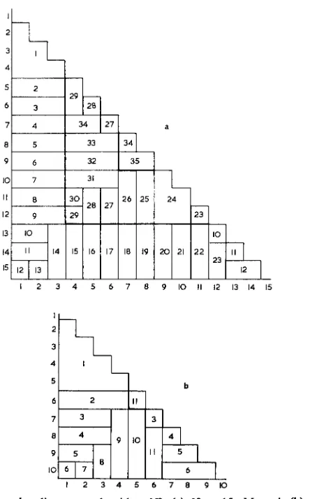
(a) Algorithm N2
This is illustrated for N = 15, M = 4 in Figure 2a, and for N = 10, M = 5 in Figure 2b. Once again the triangular diagrams are divided into nested L-shaped regions, but now each of these regions is filled with block numbers in the opposite direction from the previous one. Block numbers run consecutively round the outside of each L except in its last A4 - 2 positions. The distinctive feature of this algorithm is the method
123456 7 8 9 IO II 12 I3 14 I5
P
26 25 24 22 23
IO I8 19 20 21 II
22 23 I2
I 2
3 4
5 b
6 2 II
7 3 3
647 a 4 9 5
9 5 IO
IO 6 II 6 I 2 3 4 5 6 7 8 9 IO
FIG. 2. Triangular diagrams-algorithm N2: (a) N = 15, M = 4. (b) N = 10,
TABLE 3 ValuesofB,M>3,2M< N< 12 n Lower bound Nelder’s algorithm Algorithm N2 N
\I
N N z M 6 7 8 9 10 11 12 M \I 6 7 8 9 10 11 12 M \I 6 7 8 9 10 11 12 8 1 ___~ 3 5 7 10 12 15 19 22 3 7 9 13 16 21 25 31 3 7 10 14 18 22 27 33 3 4 5 6 8 10 11 4 8 10 12 16 19 4 9 11 14 18 22Q 5 5 6 7 5 9 11 13 5 11 13 15fj g
6 5 10 13 3 -- Algorithm N3 Algorithm N4 N
\I
M 6 7 8 9 10 11 12 6 7 8 9 10 11 12 dI -1 - 3 7 10 14 18 22 27 33 3 7 10 14 18 22 27 33 F 4 9 12 14 18 22” 4 9 11 14 18 22” 5 11 14 16 5 11 13 15H v1
92 GOWER AND PREECE
for forming blocks N - 2M + 3, N - 2A4 + 4,..., N - A4 i I in the first L, and the corresponding blocks in the other L’s.
If N > 3M - 4, then A4 - 2 elements must be transferred to form the (N - 2M + 3)th block; however if N = 3M - 5 only M - 3 need be transferred, if N = 3M - 6 only M - 4, and so on.
Tables 2 and 3 show how the values of T and B for this algorithm compare with the lower bounds, and with the values for Nelder’s algo- rithm, when N < 12 and when Nelder’s algorithm gives T > lower bound. It will be seen that Nelder’s algorithm produces values of B less than or equal to those for N2, but values of T greater than or equal to those for N2.
2
‘“1 3 4
51 2 I
29
I6 3
287 4 34 27
al 5 I 33 34 9
tt’
6 32 35 101 7 I 31-
25
12345 6 7 -
I
19 a2
‘h
3
a
b IO
It5
II23 I2 12 I3 I4 I5
a
IO 6 7 6
12345678910
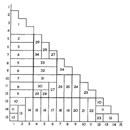
FIG. 3. Triangular diagrams-algorithm N3: (a) N = 15, M = 4. (b) N = 10,
GENERATING SUCCESSIVE INCOMPLETE BLOCKS 93
(b) Algorithm N3
This is illustrated in Figure 3. Comparison of Figures 2 and 3 shows that algorithms N2 and N3 are very similar; indeed they are identical for M = 3. The first difference for A4 > 3 is brought about by the way in which the corner of each L-shaped region is treated; for N3 the pattern in the first region is:
N-2M+2 Note these two sections
of the same size. i
‘1
N-2Mt5I
etc.
krl
‘N-M+2(When constructing designs from the triangular diagrams, care must be taken in the first L that blocks N - A4 + 2, N - A4 + 3,..., N - 2 are so formed as to permit the formation of block N - 1. Similar care is required for each subsequent L.) The other difference is in the formation of the second block for each L after the first; these blocks are got by transferring more than one variate. Going round all but the last M - 3 positions on the outside of each L, block numbers fall consecutively as follows:
94 GOWER AND PREECE
and N, T is one less for N3 than for N2. For only three sets of M and N are values of B different, and then the value for N3 is one more than the value for N2.
(c) Algorithm N4
This is so similar to previous algorithms that it is not described in detail. Figure 4 and Table 2 provide the relevant information. Algorithms N2, N3, and N4 are equivalent for A4 = 3.
9 6 32 34 IO 7 31 I I I II
12
13
14
I5
123456769 IO II 12 I3 14 15
FIG. 4. Triangular diagrams-N = 15, M = 4: algorithm N4.
(d) Algorithm NS
This generalisation of Nelder’s algorithm is illustrated by Figure 5, for which N = 13 and M = 6, and by the corresponding design
1 8 7 5 2 9 6 3 10 7 4 11 8 5 7 9 11 13 9 6 8 10 12 0
GENERATING SUCCESSIVE INCOMPLETE BLOCKS 95
0 9
9 IO 3
II
0 7 I2 4
I3 5
I 2 3 45 6 7 0 9 IO II 12 I3
FIG. 5. Triangular diagram-N = 13, A4 = 6: algorithm N5 with v = 2. number of blocks at the expense of an increease in the number of transfers. (In the example T = 23 and B = 9, whereas with v = 1 the corresponding values are 22 and 12.) In general,
T = NC1 + P) - 3Mp(l + p) + &vp(p - I),
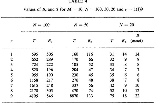
where p is the integral pair of (N - v - l)/(M - v). The number B is more difficult to compute when v > 1, because of incomplete rectangular “blocks” like numbers 5 and 8 in Figure 5; the approximation
B, = (CT - W/v) + P + 1
is an underestimate obtained by assuming that all “blocks” are complete. Tables 4 and 5 list values of T and B, for M = 10 and M = 20 and various values of N and v. The final column of Table 4 gives exact values of B when N = 20; the values agree well with those of B, especially for the smaller values of V. In Tables 4 and 5, B, is minimum when v = +M;
this result cannot be universally true as it must require modification when
M is odd, but it is fairly clear that the minimum is very close to
96 GOWER AND PREECE TABLE 4
Values of B, and Tfor M = 10, N = 100, 50,20 and u = l(l)9
N= 100 N = 50 N = 20
B
V T B* T Bo T B, (exact)
595 506 160 116 31 14 14
652 289 170 66 32 9 9
724 222 185 52 33 8 8
820 196 204 41 34 I I
955 190 230 45 35 6 6
1158 217 210 48 38 I 8
1615 248 337 56 42 9 10
2170 305 470 14 52 10 12
4195 546 8870 133 15 18 22
TABLE 5
Values of Be and T for M = 20, N = 100,50 and v = l(l)19
M = 20 N= 100 N = 50
V T B* T &
1 310 216 91 44
2 320 116 92 24
3 330 83 93 18
4 340 66 94 14
5 355 58 95 12
6 370 52 98 12
7 387 49 101 12
8 408 47 104 11
9 432 46 107 11
10 460 45 110 10
11 496 46 116 11
12 540 48 122 11
13 598 52 130 13
14 674 56 140 13
15 780 63 155 14
16 940 71 178 17
17 1207 99 215 21
18 1740 138 290 31
GENERATING SUCCESSIVE INCOMPLETE BLOCKS 97 6. Two OTHER SOLUTIONS OPTIMUM FOR T
No known algorithm always gives the smallest possible value of T. This is shown by the following two schemes, each of which has T less than could be obtained, for the same N and M, by any algorithm given above:
(9
15 78 11
2 6 5 7 10
3 1 4 3 2 5
4 9 6 8 7
N= 11, A4 = 4, T = 21 = lower bound (see Table 2).
(ii)
1 5 10 7 9 8
2 6 89 12
3 7 6 8 I1
4 1 2 1 5 4 3
1 6
N= 12, A4 = 4, T = 25 = 1 + lower bound.
REFERENCES
1. R. A. FISHER AND F. YATES, “Statistical Tables for Biological, Agricultural, and
Medical Research,” 6th ed., Oliver & Boyd, Edinburgh, 1963.
2, Pfk HAMMERSLEY, The computation of sums of squares and products on a desk calculator, Biometrics 8 (1952), 156-168.
3. G. H. Jowm-r, The calculation of sums of squares and products on a desk calculating machine, J. Roy. Statist. Sot. Ser. B 11(1949), 89-90.
4. J. A. NELDER, The efficient formation of a triangular array with restricted storage