Design and Optimization of Process Parameter
Causing Crack Defect in Draw Component of Sheet
Metal Forming By Using FEA
1Mr.Dnyaneshwar Bagde, 2Dr.K.H.Munde, 3Mr.Ashish Pawar.
1P.G.Student, 2,3Professor Department of Mechanical Engineering
APCOER, Parvati, Pune,India.
Abstract: Now a day manufacturing of uniform thick component is done with the help of forming methodology, forming
methodology involves many challenges like-punch diameter, die radius, clearance, lubricant, BHF and its trajectories etc. So designing the die tool for component needs a lot of prototype and its test procedure. To reduce number of prototype test steps, the process can be done by using finite element packages. Even the CAE gives an approximation towards the solution. The dissertation work is relevant in the context of developing a cost effective component with a lower development time through the phase of Design, Development, Trials and Testing, lot production & Regular supply. In this dissertation work, the significance of three important deep drawing process parameters namely blank Holding force, die arc radius and punch nose radius on the deep drawing characteristics was determined. Because of thickness variation in the formed component may cause thinning and may lead to acceleration of crack in the component. The CAE method is a powerful tool to predict undesirable deformations in component before prototypes are made. In this dissertation work, the combination of FEM and Taguchi design of experiments and has been used to analyze the influencing Design parameters on Thinning in automotive deep draw component.
Index Terms: Material damage, sheet metal forming, CGA (Circle Grid Analysis), r/t ratio
________________________________________________________________________________________________________
I. INTRODUCTION
An oil filter is a component generally useful to remove dust particles and mud from engine oil, gear sump oil, lubrication oil, or hydraulic oil. Applications of oil filter cap in many different types of machinery and automotive. A huge use of the oil filter is in automotive sector like IC engines in automotive and non-automotive, light aircraft, and various naval vessels application. Generally hydraulic application carried out in, auto operation and power steering application, many of times uses oil filter. Gas turbine engines oil mechanism, oil filters are used in jet and heavy navvy application also. Beside from these uses, oil production, transport, and recycling facilities also employ filters in the manufacturing process. These oil filters are manufacture using sheet metal stamping and deep drawing process. Sometimes we get defects during manufacturing. Its manufacturing process and its occurrences of defects are explained below.
Deep drawing method is on of the sheet metal forming process where depth of draw is greater than diameter of draw. Metal is highly get stressed in the die shoulder area there is the lot stress concentration, and will result in wrinkles, if a blank holder is not having a good control on material flow in to die. Material is becomes thicker when the metal loses contact with the punch radius and thin in which the areas where stress concentration is large. Stamping process many of time used to produce metal objects. The metal is deformed around a punch in die cavity. In the deep drawing process, when blank is comes under blank holder then it drawn into the deformation by the punch. The aim of the forming industry is to give best quality product with eliminating failures and optimizing the process parameters. Failure in component occurs in the deep drawing process for e.g wrinkle and thinning or crack. The effect of shape of the blank and BHF on wrinkle& thinning crack was investigated.
Sheet metal drawing is a efficient technique which manly used to manufacturing body parts in automobile industries. In sheet metal drawing process, a thin sheet is subjected to permanent deformation using draw die tools to conform the get the designed shape. During this process, there are chances of produces defective component when process parameters are not selected properly. For good quality of product and reduction in component defect to optimize the process parameter and reduce the production cost. Following process parameters are having a major influence on the process such as die corner radius, BHF, friction coefficient, etc. Taguchi technique play important role in sheet metal drawing process studies to design the experiments and determines the influence of process parameters on characteristics of the component.
II. LITRATURE REVIEW
deep drawing process and behaviour of component in order to produce defect less product. This study provided stainless steel blank sheet in the deep drawing. The quality of product depends on the drawing environment and the optimize value of parameters and their effective combination is important for forming process.
J. Pradeepkumar et al.[2] suggested that the repercussion table for S/N ratio and standard deviations shows in order to impact of the process parameters of product Punch Nose Radius, BHF Punch Force. The Single to noise ratio graph shows that the initially it decreases and then increases. So it suggesting that the point for high single noise ratio gives good results. Also the values of standard deviation decreases with the value of increase in punch force. According to above graph the higher values of punch force gives better results. Graph shows the linear relationship between BHF and single noise ratio. For better quality product higher single noise ratio lower std deviation lower BHF gives the optimum results. Thus a lower BHF confirms uniform thickness by avoid to give extra pressure on the flange. The analyse the predicted values with the help of regression equation for the std. deviation FEM with Taguchi method also used to find out the proportion of contribution of three important process parameters in the manufacturing deep-drawing component namely die radius, BHF, punch nose radius and punch velocity. ANOVA was done to analyse the impact of process parameters on the drawing and their % contribution.
G.Venkateswarlu et al. [3] investigated with the help of FEM with Taguchi method also used to find out the proportion of contribution of three important process parameters in the manufacturing deep-drawing component namely die radius, BHF, punch nose radius and friction coefficient. Graph shows the linear relationship between BHF and single noise ratio. For better quality product higher single noise ratio lower std deviation lower BHF gives the optimum results. Thus a lower BHF confirms uniform thickness by avoid to give extra pressure on the flange. The analyse the predicted values with the help of regression equation for the std. deviation.
III.PROBLEM STATEMENT
The Sheet metal forming and drawing industry is faced with a lot of challenges while developing a Tool (Die). For a component which is manufacturing by a deep draw operation. The work is critical in nature and it required high competency on the part of design as well as the material property and the process factors.
Wrinkles’- Wrinkles coming start in the component due to the 1) Compressive instability, 2) Unbalanced blank holder pressure,
3) Draw radius too large
Thinning- Material undergoes extra deformation; Due to punch-die clearance is to small, uncontrolled BHF.
Fracture- Draw radius and blank holding surface deformed excessively, Punch nose and draw radius are to small.
Spring Back- When the bending operation done and stress get removed at the end of the completion of operation, the material is tray to regain its original position. This is only the part of `elastic recovery’ i.e. the Spring back.
IV.OBJECTIVES
The main objective of work is correctly efficiently simulate and optimize the crack defect in sheet metal deep drawing processes of sheet metal part and to subsequently link them together depending on the process requirements. This was expected to enable tool designers to numerically calculate the sheet metal forming tool and process design and to then enable redesign where necessary in order to meet the requirements of producing desired shapes using these coupled processes.
Specific Objectives are:
1) To investigate the various types of defect occurs in the part due to the effect of various process parameter and tool geometry 2) To avoid Excessive thinning in areas of the sheet metal part
3) Controlling the parameters like blank holder force, radius on die, radius on punch which affecting on thinning in deep drawing Process using Design of Experiment and FEA.
SCOPE OF THE WORK
To evaluate the part design for draw ability.
Generate a General Layout for the Die for the subject part.
Analyze the part for Draw operation using appropriate CAE software for Forming/ Draw simulation.
Interpret the results.
Design the die and finalize the specifications and Conduct trials for experimentation.
Document the results for validation
To design tool and development for component is very costly process it required lot a time if we work conventionally. So we can use advance technology such as FEA during the design phase so that problem areas in forming can be easily pointed out through analysis results which will make our work, time and cost effective. And based on analysis report tool designer can suggest revisions/ modifications in the product design which will help tool designer to design a tool which will produce defect free components based on the inputs received.
After calculating process sequences and process parameters the forming dies are designed using sophisticated CAD systems. However still we don’t have any evidence whether the designed tool will provide the right component and as it is die goes for tri-out and automatically it consumes time and cost and it will effects on the final cost of the die.
V. DESIGN OF EXPERIMENT Design Parameter
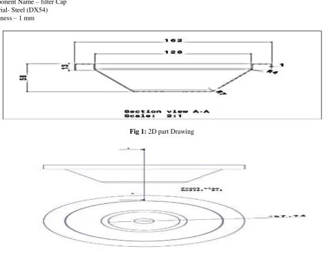
Component Name – filter Cap Material- Steel (DX54) Thickness – 1 mm
Fig 1: 2D part Drawing
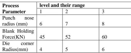
Fig 2: 2D part Drawing
Developed Blank Diameter = D
=√ (d2)2+2(d1+d2) h+ (d23-d22) =237 mm
Draw Ratio = H/d =56/128 =0.4375 ≤0.75
Draw Force –
Draw Force can be calculated P = п.d. t. s. ((D/d) – C) Where, P = Draw Force in N
t = Thickness of Metal in mm = 1 mm
S = Yield strength of Metal in Kg/mm2 =280Mpa C = Constant (Take 0.6 to 0.7) =0.6
Therefore, Draw Force (P) =178KN
Draw & Punch radius –
The Draw radius ranges from 4 to 8 times the Blank thickness. Therefore,
Radius of Draw Die = Rd =4 x 1 = 4mm
The Punch Nose radius ranges from 4 to 12 times the Blank thickness Therefore,
Radius of Punch = Rp =7 x 1 =7 mm
Blank Holding Force –
Blank Holding Force (B.H.F.) is 25 % to 33% of Draw Force Therefore B.H.F. can be calculated as,
Blank Holding Force (B.H.F.) = 33 % of Draw Force = 0.33x 178=60 KN
VI. TAGUCHI TECHNIQUES
Taguchi proposed several approaches to experimental designs called Taguchi method. This method utilizes an orthogonal array, which is a form of fractional factorial design containing representative set of all possible combination of experimental conditions. Using Taguchi method, a balanced comparison of levels of the process parameters and significant reduction in the total number of required simulations can both be achieved.
In the present study, Taguchi method of experimental design was used to plan the numerical simulations. In Taguchi method design, using two levels of each variable factors form screening experiments to determine a model of the system to a linear approximation. By this, the least influential parameters are identified and eliminated before the most influential process parameters can be further studied.
Table 6.1: Orthogonal array (L9) of Taguchi method
Table6.1 shows the chosen process parameters and their levels used in the FE simulations. The high order interactions among the above three factors are assumed negligible and the information on the main effects can be obtained by running 3³=27 experiments. However, the appropriate Taguchi orthogonal array for the above three parameters with three levels is L9 to conduct nine simulations, Table 6.2. The first column represents the number of simulation and the subsequent columns represent the process parameters and the rows represent simulations with the levels of each parameter. After the experiments are designed with various combinations of process parameter levels, FE simulations were carried out to predict the deformation behaviour of the blank sheet.
Process Parameter
level and their range
1 2 3
Punch nose
radius (mm) 6 7 8
Blank Holding
Force(KN) 45 52 60
Die corner
Table 6.2: Orthogonal array (L9) of Taguchi method
Table 6.3: Process Parameter and Their Level
VII. FINITE ELEMENT ANALYSIS
SOFTWARE FOR DESIGN AND ANALYSIS:
CATIA V5R20 for Solid Modeling.
Forming Suite (FASTFORM) for Simulation
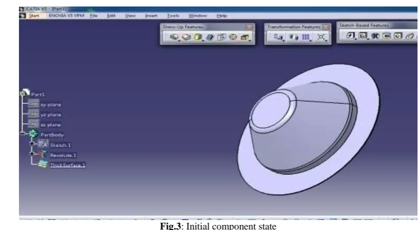
CAD model of component
Fig.3: Initial component state Expt.No.
Parameter
Punch nose Radius
Blank Holding
Force
Die corner radius
1 6 45 4
2 6 52 5
3 6 60 6
4 7 45 5
5 7 52 6
6 7 60 4
7 8 45 6
8 8 52 4
Fig.4: Final component state
Table 7.1: Mechanical Properties of DX53 Steel material
Mechanical Properties
Tensile strength (min) Mpa 280 MPa
Yield strength 0.2% carbon 208.2 MPa
% Elongation (min) 40%
Plastic strain ratio 'r' value (min) 1.7
Strain Hardening exponent, 'n' value 0.3
Modulus of elasticity(E) 205000 MPa
Poisson ratio(nu) 0.3
Simulation of Component.
As we selected the L9 orthogonal array, we did 9 experiments in Fastform software & took the thickness of the various region of the component showing in figures. Thickness distributions of nine experiments showing below.
Experiment No. 1
Punch nose Radius=6mm, Blank holding force=45KN, Die corner Radius=4mm
Fig.5:-Thickness distributions of Expt. No. 1
Experiment No.2
Punch nose Radius=6mm, Blank holding force=52KN, Die corner Radius=5mm
Fig.6:-Thickness distributions of Expt. No. 2
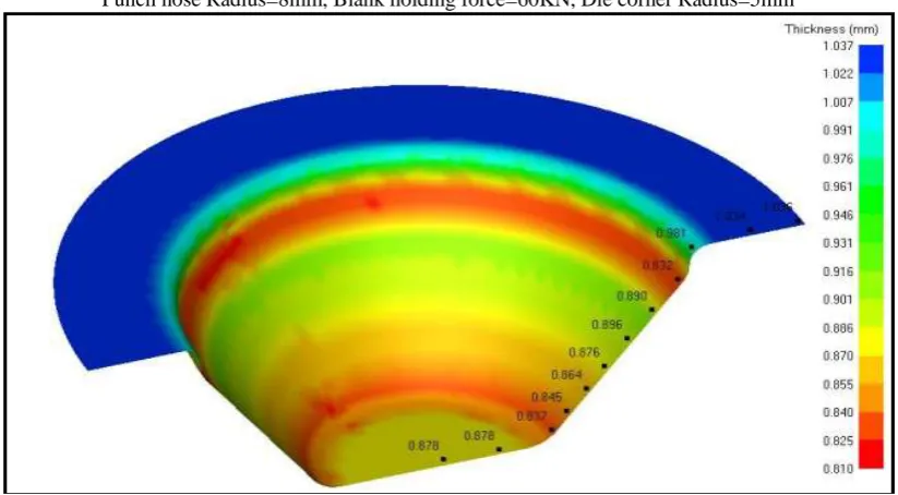
Experiment No.3
Punch nose Radius=6mm, Blank holding force=60KN, Die corner Radius=6mm
Fig.7:-Thickness distributions of Expt. No. 3
Experiment No.4
Punch nose Radius=7mm, Blank holding force=45KN, Die corner Radius=5mm
Experiment No.5
Punch nose Radius=7mm, Blank holding force=52KN, Die corner Radius=6mm
Fig.9: Thickness distributions of Expt. No. 5 Experiment No.6
Punch nose Radius=7mm, Blank holding force=60KN, Die corner Radius=4mm
Fig.10: Thickness distributions of Expt. No. 6 Experiment No.7
Punch nose Radius=8mm, Blank holding force=45KN, Die corner Radius=6mm
Fig.11: Thickness distributions of Expt. No. 7 Experiment No.8
Punch nose Radius=8mm, Blank holding force=52KN, Die corner Radius=4mm
Experiment No.9
Punch nose Radius=8mm, Blank holding force=60KN, Die corner Radius=5mm
Fig.13: Thickness distributions of Expt. No. 9
Table No7.3: Average thickness (mean) for nine experiments.
Table No7.3: Average thickness (mean) for nine experiments
Expt. No. Rp BHF Rd Thinning
1 6 45 4 0.900583
2 6 52 5 0.9055
3 6 60 6 0.910417
4 7 45 5 0.902917
5 7 52 6 0.913833
6 7 60 4 0.902167
7 8 45 6 0.92
8 8 52 4 0.902333
VIII. EXPERIMENTATION
We carried out experimentation over a suitable press machine based On the 100 tonnage for the component. As per Work, we Took the Inputs from analysis of variance (ANOVA) which
Is given for experimentation i.e.Rp=8mm, BHF=45KN,Rd=6mm
Fig.14: Press Machine
Fig.15: Punch
Fig.16: Die
Fig.18: Safety final (defect less) component
IX. RESULT AND DISCUSSION-
9.1 Safety Result-
Fig.19: FEA Result (fig. indicates the same area colour wise)
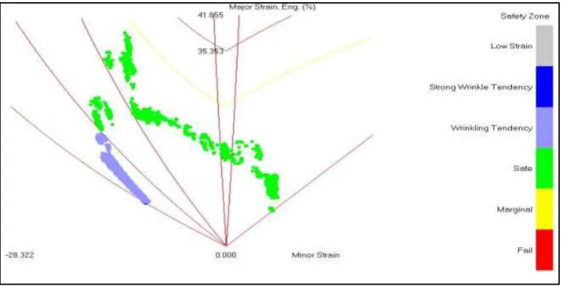
Fig.21: Forming limit diagram
Table no.9.5: comparison between simulation and experimental thickness value
Measured
Position Thickness from FEA
Thickness from Experiment test
1 0.883 0.89
2 0.883 0.88
3 0.851 0.86
4 0.869 0.875
5 0.88 0.89
6 0.895 0.89
7 0.917 0.93
8 0.893 0.9
9 0.881 0.87
10 1.015 1.01
11 1.035 1.05
12 1.038 1.05
X. CONCLUSION AND FUTURE SCOPE OF WORK
Large thinning & fractures in areas of the sheet metal is an unwanted defect. Excessive thinning will most likely occur on the side wall, near the base of the part. So minimization of Thinning is important in deep drawing process. The parameters affecting on thinning in deep drawing are nose radius, blank holder force and Die shoulder radius. By controlling all these parameters minimization of thinning occurs. Here, in this project, Taguchi method with Flower Pollination Algorithm is used to optimize the thinning in deep drawing. Simulation technique used effectively to optimize the die design and process parameters. So it is concluded that the proposed optimization approach is successful and it is Validated with experiments which reduce the cycle time and material cost.
In future work after draw operation of filter cap, there in next operation is trimming to get the final products so we can modify the die design & can try to get both operations. Drawing & cutting in a single 11stroke. I.e. called combination die. In order to expand the range of application of the developed method, parts with more complex geometries can be considered as future scope of work
ACKNOWLEDGEMENT
The authors are thankful to Prof.G.E.Kondhalkar, Head,of Mechanical Engg. Dept.,Dr.K.H.Munde, PG Coordinator & Guide, And Dr.S.B.Thakare, Principal, for their timely support, guidance and providing necessary facilities. The authors also extend their gratitude to Mr.Ashish Pawar prof. of Mechanical Engg. Dept.
REFERENCES
[1] R. Padmanabhan, M.C. Oliveira, J.L. Alves, L.F. Menezes, Influence of process parameters on the deep drawing of stainless steel, ScienceDirect ,Finite Elements in Analysis and Design 43 (2007) 1062 – 1067
[2] J. PradeepKumar, M. Bilal Tanveer, Sagar.A. Makwana, R. Sivakumar,Experimental Investigation and Optimization of Process Parameters on the Deep Drawing of AISI202 Stainless Steel, International Journal of Engineering Research & Technology (IJERT) ISSN: 2278-0181, Vol. 2 Issue 4, April – 2013
[3] G.Venkateswarlu,M. J. Davidson and G. R. N. Tagore, Influence of process parameters on the cup drawing of aluminium 7075 sheet, International Journal of Engineering, Science and Technology Vol. 2, No. 11, 2010, pp. 41-49
[4] Fuh-Kuo Chen,Yeu-Ching Liao, Analysis of draw-wall wrinkling in the stamping of a motorcycle oil tank, Journal of Materials Processing Technology ,192–193 (2007),pp. 200–203
[5] Tool design data book for Diploma in Mechanical engineering (Tool & Die) course code 1220 directorate of technical education government of Tamilnadu.
[6] H. Zein, M. El-Sherbiny, M. Abd-Rabou, M. El Shazly,Effect of Die Design Parameters on Thinning of Sheet Metal in the Deep Drawing Process, American Journal of Mechanical Engineering, 2013, Vol. 1, No. 2,pp. 20-29
[7] R. Venkat Reddy,Dr T.A. Janardhan Reddy,Dr.G.C.M. Reddy, Effect of Various Parameters on the Wrinkling In Deep Drawing Cylindrical Cups, International Journal of Engineering Trends and Technology- Volume3Issue1- 2012,pp.53-58
[8] Y. N. Dhulugade, P. N. Gore,Design and Development of Sheet Metal Draw Component Using CAE Technology, International Journal of Emerging Technology and Advanced Engineering ,Volume 3, Issue 3, March 2013,pp.30-39
[9] Mr.Amit D. Madake1, Dr.Vinayak R. Naik2 Development of a Sheet-Metal Component with a Forming Die Using CAE Software Tools (Hyper form) For Design Validation and Improvement, International Journal of Modern Engineering Research, Vol. 3, Issue. 3,May-June. 2013 ,pp-1787-1791
[10] S. Raju, G. Ganesan, R. Karthikeyan, Influence of variables in deep drawing of AA 6061 sheet,ScienceDirect,Transaction of Nonferrous Metals Society of China 20(2010)1856-1862