Wireless Human Physiological Index Acquisition System Based on
RF Technology
Yang LIU
School of Information Science & Electric Engineering, Shandong Jiaotong University, China
I.
INTRODUCTION
In recent years, with the development of wireless communication technology, 433MHz frequency band because of its wireless signal penetrating ability and other advantages are gradually widely used in medicine, industry, scientific research. Body-based network is a long-term monitoring and recording of human health signals of the basic technology, early mainly used to monitor and record the health parameters of chronic diseases. The future of the body network can also be widely used in consumer electronics, entertainment, sports, environmental intelligence, animal husbandry, military or security and other fields. The latest technologies such as integrated circuits, wireless communications and other rapid development, allowing more small, ultra-low power, lightweight intelligent monitoring equipment. Wireless communication technology used in the medical field for the implementation of remote monitoring of patients is the current and future trends [1][2].
With the rapid development of science and technology and the continuous improvement of living standards, people are increasingly concerned about their physical condition, monitoring came into being, technology, including computer technology, communication technology, multimedia technology and medical technology, Is a multidisciplinary combination of cutting-edge science, based on radio frequency technology of human physiological indicators to collect wireless transceiver system is a simple and effective design for remote medical care. It also plays a key role in the monitoring of physiological indicators in remote areas and mountain populations [3][4]. Now the hospital generally takes a fixed medical monitoring equipment, through the data lines and so on to connect patients and equipment, and the need to enter the information into the computer, and finally make the analysis and diagnosis. This traditional medical monitoring system is largely tied to the freedom of the patient, and the traditional medical monitoring system to get the results of the process is very slow, and sometimes the need for doctors to determine the final treatment plan, this approach is often a lot of waste Manpower and material resources.
Human physiological indicators are the most important and basic life characteristics of the human body, and the monitoring of a number of physiological indicators of the injured persons can help to grasp the patient's condition in real time and timely and effective treatment [5]. But most of our current use of artificial bedside monitoring or wired bed monitoring, so not only a waste of human, material and costly, and some remote areas of poor patients because of medical conditions and many other factors physiological indicators cannot be timely collection. Also cannot find the problem in time to receive treatment. Therefore, based on the radio frequency technology of human physiological indicators of wireless transceiver system research to help better access to the patient’s physiological indicators in time, found that lesions, timely treatment, there is great practical significance
[6]
.
Abstract:
To collet human physiological indicators with RF technology, wireless system is a new cutting-edge areas of research. It uses different functions of sensors to collect the body's physiological indicators by small loop antenna, BPF, transceiver switch and PA to send and receive dates. Now most researches are based on 2.4GHz, but this method has small area of coverage, small gain of antenna, and it is possible to introduce big errors when testing. Therefore, this paper studies and explores the feasibility of antenna based on 433MHz. To design the RF circuit, calculations and simulations are made to get the parameters of antenna. The small loop antenna based on 433MHz has a more broad area of coverage, lower power, lower cost, and higher reliability.Radioactive technology based on radio frequency technology The wireless transceiver system consists of a series of lightweight devices that can monitor biological signals and transmit them wireless to the terminal system of the health care center [7][8]. Health care experts through reliable connection technology to obtain patient data, the patient for remote diagnosis and treatment. This approach can shorten the patient's hospital stay, but also allows patients to obtain complete freedom, thereby improving the quality of life of patients, but also reduce the waste of resources. With the rapid development of society, based on the radio frequency technology of human physiological indicators to collect wireless transceiver system is from theory to practice, this research is a benefit of mankind has far-reaching significance of research, has broad prospects for development. From the perspective of the whole society, the extensive use of human physiological parameter acquisition and monitoring system can improve people's quality of life and prolong human life. It is necessary to realize the collection and monitoring of human physiological parameters, and it has certain social significance [9][10].
II.
SYSTEM
PLAN
1. System overall design overview and functional analysis
RF is a long-distance transmission of high-frequency electromagnetic waves, radio frequency technology using radio frequency for non-contact two-way data transmission, in order to achieve the purpose of target recognition and data exchange. Based on the radio frequency technology of human physiological indicators to collect the wireless transceiver system to meet the requirements:
(1) the entire system design should be based on RF technology, the use of high-frequency electromagnetic waves to achieve long-distance transmission;
(2) the system to low power consumption, and to meet the long-distance transmission; (3) the system size is small, easy to carry and use;
(4) launch and acceptance module must have a strong anti-jamming performance; (5) the reliability and feasibility of the system.
2. Small loop antenna design
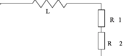
Schematic diagram of small loop antenna Equivalent As shown in Figure 1, the equivalent circuit is equivalent to two series resistance and an induct series. R1 is the loop antenna actual emission energy of the resistance model, which consumes the power of the circuit is the transmission power. Assuming that the current flowing through the antenna loop is I, then the power consumption of R1, that is, the power of RF is P1 = I • R1. Resistor R2 is the resistance model of the loop antenna that consumes energy due to heat. The power consumed by it is an unavoidable energy loss with a size of P2 = I2 • R2. The power consumed by the antenna is the sum of the transmit power and the loss power. P1 is determined by the size of the conductor making the antenna and the conductivity of the conductor, and P2 is determined by the size of the area enclosed by the antenna.
Fig. 1 The equivalent circuit of the small Loop Antenna
3. Filter design
According to the requirements of the entire circuit system on the filter, the design of the best working state of the high-frequency band-pass filter circuit to ensure the normal operation of the entire circuit.
Band pass filter is actually a tuning circuit, by changing the circuit capacitance, inductance, resistance, change the oscillation frequency of the circuit, when the signal tuning frequency and the oscillation frequency of the circuit coincide, the circuit resonance, all signal frequency in the band Pass the filter through the band within the signal can be passed, the other frequency of the signal is blocked.
An ideal band pass filter has a perfectly flat pass band with no gain or attenuation in the pass band and all frequencies outside the pass band are completely attenuated, and the pass band conversion is done in a very small frequency range The In practice, however, there is no such ideal band pass filter. The filter is not able to completely attenuate all the extraneous frequencies outside the desired frequency range, which is often referred to as the roll-off phenomenon of the filter, using the decay amplitude dB per ten octave. In general, the design of the filter as much as possible to ensure that the roll range narrowed the better, so the performance of the filter and design closer.
4. Low noise amplifier
The usual low noise amplifiers are designed according to the noise best match, while the noise best match is not the maximum gain point, where the gain is the correlation gain. The operating band of the low noise amplifier is the frequency range in which the power gain satisfies the flatness requirement, and the noise in the whole band is satisfied, and the noise figure of each frequency point is given.
The low noise amplifier is used for the front end of the receiver at the RF front end, so the smaller the noise figure is, the lower the noise signal is, and the low noise amplifier is a small signal amplifier. Moreover, due to the influence of the transmission path, the signal is constantly changing, and it is possible to input a large associated disturbance signal while receiving the signal. Therefore, the amplifier is required to have a sufficient linear range and preferably have an adjustable gain. The low noise amplifier is typically connected directly to the filter or to the antenna via the transmission line, so the input of the amplifier must match the antenna or filter so that the maximum power transmission or the minimum noise figure, and the low noise amplifier should Has a certain frequency selection function. The main function of the low-noise amplifier is to amplify the weak signal received by the antenna, reduce the noise interference, in order to improve the received signal sensitivity for the system to demodulate the required information data, its noise, linearity and matching performance directly affects Performance of the entire receiving system.
Common low noise amplifiers can be divided into three types: CMOS, JFET and bipolar. The JFET input low noise amplifier has a low input current noise density and is designed to allow a single power supply to operate, but the power supply impedance must be as low as possible, and the power supply impedance must be as low as possible. Voltage noise is large; CMOS input low noise amplifier current noise is good.
III.
CIRCUIT
SIMULATION
1. Antenna simulation
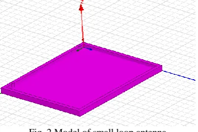
Fig. 2 shows the simulation results of small loop antenna. Fig. 3 is the simulation results of the radiation of antenna.
Fig. 3 Radiation of antenna
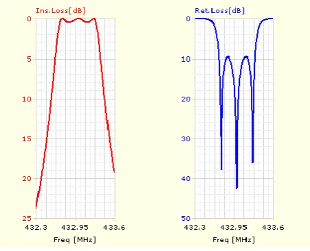
2. BPF simulation
Fig. 4 shows insertion loss and return loss of the BPF with the central frequency 433 MHZ, which is done in Ansoft Designer software.
Fig. 4 Simulation diagram of BPF
3. Amplifier simulation
IV.
CONCLUSIONS
To collet human physiological indicators with RF technology, wireless system is a new cutting-edge areas of research. It uses different functions of sensors to collect the body's physiological indicators by small loop antenna, BPF, transceiver switch and PA to send and receive dates. Now most researches are based on 2.4GHz, but this method has small area of coverage, small gain of antenna, and it is possible to introduce big errors when testing. Therefore, this paper studies and explores the feasibility of antenna based on 433MHz. To design the RF circuit, calculations and simulations are made to get the parameters of antenna. The small loop antenna based on 433MHz has a more broad area of coverage, lower power, lower cost, and higher reliability.
REFERENCES
[1] Berka C, Levendowski D J, Cvetinovic M M, et al. Real-time analysis of EEG indexes of alertness, cognition, and memory acquired with a wireless EEG headset[J]. International Journal of
Human-Computer Interaction, 2004, 17(2): 151-170.
[2] Pandian P S, Safeer K P, Gupta P, et al. Wireless sensor network for wearable physiological monitoring[J]. JNW, 2008, 3(5): 21-29.
[3] Lin C T, Chen Y C, Huang T Y, et al. Development of wireless brain computer interface with embedded multitask scheduling and its application on real-time driver's drowsiness detection and warning[J]. IEEE
Transactions on Biomedical Engineering, 2008, 55(5): 1582-1591.
[4] Chuo Y, Marzencki M, Hung B, et al. Mechanically flexible wireless multisensor platform for human physical activity and vitals monitoring[J]. IEEE transactions on biomedical circuits and systems, 2010, 4(5): 281-294.
[5] Lin C T, Ko L W, Chiou J C, et al. Noninvasive neural prostheses using mobile and wireless EEG[J].
Proceedings of the IEEE, 2008, 96(7): 1167-1183.
[6] Bansal D, Khan M, Salhan A K. Real time acquisition and PC to PC wireless transmission of human carotid pulse waveform[J]. Computers in Biology and Medicine, 2009, 39(10): 915-920.
[7] Kim Y S, Baek H J, Kim J S, et al. Helmet-based physiological signal monitoring system[J]. European Journal of Applied Physiology, 2009, 105(3): 365-372.
[8] Rani P, Sarkar N, Adams J. Anxiety-based affective communication for implicit human–machine interaction[J]. Advanced Engineering Informatics, 2007, 21(3): 323-334.
[9] Valdastri P, Menciassi A, Arena A, et al. An implantable telemetry platform system for in vivo monitoring of physiological parameters[J]. IEEE Transactions on Information Technology in Biomedicine, 2004, 8(3): 271-278.
[10] Antonenko P, Paas F, Grabner R, et al. Using electroencephalography to measure cognitive load[J].