144
SPEED CONTROL OF THREE PHASE INDUCTION MOTOR By SENSORLESS
VECTOR
Swati Raghuwanshi
1, A.P. Singh
2Department of Electrical and Electronics
Truba College of Science and Technology
Abstract:-In this paper we present a sensor less vector control method for controlling the speed of induction motor. Vector control method is based upon the field-oriented co-ordinates aligned within direction of the rotor MMF of induction motor. Induction motor Experiment completed on MATLAB.
Keywords: Induction motor, sensor less vector control, indirect vector control, MRAS, DSP controller.
1. INTRODUCTION
An induction machine, especially squirrel cage induction machine, has many advantages when compared with DC machine. Some of the advantages like, it is very cheap, it has very compact structure and insensitive to environment and, it does not require periodic maintenance like DC motors. When induction motor coupled with dynamic load, its properties is more nonlinear and hence requires more complex control schemes than DC motors. Traditional open-loop control of the induction machine with variable frequency may provide a satisfactory solution under limited conditions.
Power electronic switches can provide new impulse and can handle variable speed applications of both DC and AC machines. The former typically use thyristor controlled rectifiers to provide high performance torque, speed and flux control. Variable speed IM drives use mainly PWM techniques to generate a poly phase supply of a given frequency. Most of these induction motor drives are based
on keeping a constant voltage/frequency (V/f) ratio in order to maintain a constant flux in the machine. Although the control of V/f drives is relatively simple, the torque and flux dynamic performance is extremely poor. As a consequence, great quantities of industrial applications that require good torque, speed or position control still use DC machines. The advantages of induction machines are clear in terms of robustness and price; however it was not until the development and implementation of field orientated control that induction machines were able to compete with DC machines in high performance applications. Classical controller like PI controller has been used for the speed regulation to generate a command current for last two decades, and accepted by industry because of its simplicity. Even though, a well-tuned PI controller performs satisfactorily for a field-oriented induction machine during steady state. The speed response of the machine at transient, especially for the variable speed tracking, may sometimes be problematic. In last two decades, alternative control algorithms for the speed regulation were investigated. The various speed estimation methods are:
1. Kalman filter techniques
2. Model Reference Adaptive Systems (MRAS) 3. Sliding mode flux and speed estimators. 4. Neural network flux and speed estimators 5. Adaptive observers based on both voltage and
145 In Model Reference Adaptive Systems (MRAS) method, a comparison is made between the outputs of two estimators [8, 10]. The estimator which does not contain the quantity to be estimated can be considered as a reference model of the induction machine. The other one which contains the estimated quantity is considered as an adjustable model. The error between these two estimators is used as an input to an adaptation mechanism. For sensor less control algorithms most of the times the quantity which differs the reference model from the adjustable model is the rotor speed. The estimated rotor speed in the adjustable model is changed in such a way that the difference between two estimators converges to zero asymptotically, and the estimated rotor speed will be equal to actual rotor speed. The speed and rotor-flux of an induction machine can be identify by using Kalman filter (KF), based on the measured quantities such as stator current and voltage [11]. Kalman filter approach is based on the system model and a mathematical model describing the induction motor dynamics. Parameter deviations and measurement disturbance are taken into consideration in KF. For this purpose covariance matrices of the KF must be properly initialized. KF itself works for linear systems, so for non-linear induction motor model extended Kalman filter (EKF) is used [12]. However, KF approach is computationally intensive and depends on the accuracy of the model of the motor. Over the past two decades a great deal of work has been done into techniques such as Field Oriented Control, Direct Torque Control and Space Vector Pulse Width Modulation. Another emerging area of research involves the application of sensorless control. This differs from conventional methods because it doesn’t require mechanical speed or position sensors. Removing these sensors provides a number of advantages such as lower production costs, reduced size, increased reliability and elimination of excess cabling. Sensorless drives are
also more suitable for harsh inaccessible environments as they require less maintenance. This work is mainly focused on the sensorless vector control of induction motor. For this purpose, model reference adaptive system (MRAS) is used to estimate the rotor speed. Using this technique, one can obtain very precise flux and speed information as shown in the simulation and tested results. In this work proposed first the Dynamic model of induction machine which developed in the arbitrary reference frame. Second model prepared with the help of synchronous reference frame model the indirect field oriented vector control, which is very popular and convenient method in real time implementation was developed and third, Model Reference Adaptive System is studied as a state estimator. Rotor flux estimation scheme is applied to MRAS algorithm to estimate rotor speed.
2.1 MATHEMATICAL MODEL OF INDUCTION
MOTOR
The two names for the same type of motor, Induction motor and Asynchronous motor, describe the two characteristics in which this type of motor differs from DC motors and synchronous motors. Induction refers to the fact that the field in the rotor is induced by the stator currents, and asynchronous refers to the fact that the rotor speed is not equal to the stator frequency.
2.1.1 GENERALISED MODEL IN ARBITARY
REFERENCE- FRAME
Equivalent circuit diagram of three phase induction motor is shown in figure 1. Mathematical representation of motor is shown below, − and − circuits and their variables in an arbitrary rotating − frame, [1] can write the stator circuit equations as:
)
(
qs qr mqs ls
qs
L
i
L
i
i
146
)
(
qs qr mqr lr
qr
L
i
L
i
i
(2))
(
qs qr mqm
L
i
i
(3))
(
ds dr mds ls
ds
L
i
L
i
i
(4))
(
ds dr mdr ls
dr
L
i
L
i
i
(5))
(
ds dr mdm
L
i
i
(6)Fig.1 (a) Dynamic qa equivalent circuit
Fig.1 (b) Dynamic model da equivalent circuit
2.1.2 SYNCHRONOUS FRAME REFERENCE
MODEL
The speed of the reference frame is that of the stator, which
is zero; hence ωa= ωe. The resulting model equations are
obtained by substituting ωa=. ωe .
ds e qs qs s qs
w
dt
d
i
R
V
(
)
(7)qs e ds ds s ds
w
dt
d
i
R
V
(
)
(8)dr r e qr qr r
qr
w
w
dt
d
i
R
V
(
)
(
)
(9)qr r e dr dr r
dr
w
w
dt
d
i
R
V
(
)
(
)
(10)3. IMPLEMENTATION & RESULTS ANALYSIS
The inputs of a squirrel cage induction machine are the three-phase voltages, their fundamental frequency, and the loadtorque. The outputs, on the other hand, are the three phase currents, the electrical torque, and the rotor speed. The d-q model requires that all the three-phase variables have to be transformed to the two-phase arbitrary rotating frame. Consequently, the induction machine model will have blocks transforming the three-phase voltages to the d-q frame andthe d-q currents back tothree-phase. There are four important blocks present in D-Q model implementation of simulink.
Fig.2 Simulation model of induction motor
147 3.1 SIMULATION RESULTS
Sensor less vector control simulation of the induction motor is presented below.
The response of the induction motor is shown in two different cases,
1. with step changes in speed reference and load torque 2. with speed reversal (Four quadrant operation)
Fig.4 Estimated and reference speed of the motor with step changes in load torque with MRAS.
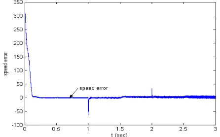
Fig. 5 speed error of the motor for changes in speed and load torque.
4. CONCLUSION
Generalized dynamic mathematical model of the induction motor is simulated in different reference frames. The speed and Torque waveforms are independent of the type of reference frame used but the d and q axes flux and current components depend on type of reference frame used.
Fig. 6 Generated torque of the motor with step changes in load torque with MRAS
Fig.6 Estimated q-axis stator current of IM with changes in speed and torque
Fig.7 d-axis rotor flux of IM with changes in speed and torque with MRAS
148 observer were fed to an open-loop speed estimator. Using this observer, Sensorless vector control is simulated and dq-axis rotor-stator fluxes, rotor speed were estimated and found satisfactory as shown in the simulations Graphs. In Sensorless vector control also proper field orientation is achieved because the value of q axis flux is zero and there is no change in d axis current due to the application of load torque.
REFERENCES
1. D. W. Novotny and T. A. Lipo, “Vector Control and Dynamics of AC Drives”, Oxford University Press Inc., Oxford, New York, 1997.
2. K.B. Nordin and D.W. Novotny “The influence of motor parameter deviations in feed forward field orientation drives systems” IEEE Tran. IA, vol. 21, pp.1009-1015, July 1985.
3. R.Krishnan, F. C. Doran “Study of parameter sensitivity in high performance inverter-fed induction motor drive systems”, IEEE Tran. IA, vol. 23, pp.623-635, 1987.
4. S. W. Matthew, W. Dunnigan and W. Williams “Modeling and Simulation of Induction Machine Vector Control with Rotor Resistance Identification” IEEE PE Tran. vol.12, no. 13, pp. 495-506, May 1997. 5. K. K. Shyu, H. J. Shieh and S. S. Fu “Model
Reference Adaptive Speed Control for Induction Motor Drive Using Neural Network ”, IEEE Tran. IE vol. 45, no. 1 pp. 180-182, Feb. 1998.
6. H. Sugimoto and S. Tamai “Secondary Resistance Identification of an Induction Motor Applied Model Reference Adaptive System and its Characteristics” IEEE Tran. IA vol. 23, no. 2 pp. 296-303 March/April 1987.
7. R. Gabriel, W. Leonhard and C. Nordby “Field oriented control of standard AC motor using
microprocessor”, IEEE Tran. IA, vol.16, no.2, pp.186.192, 1980.
8. L. Zhen and L. Xu “Sensorless Field Orientation Control of Induction Machines Based on Mutual MRAS Scheme” IEEE Tran. IE vol. 45 no. 5, pp. 824-831, October 1998.
9. H. W. Kim and S. K. Sul “A New Motor Speed Estimator using Kalman Filter in Low Speed Range”, IEEE Tran. IE vol. 43, no. 4, pp. 498-504, Aug. 1996. 10. Y. R. Kim, S. K. Sul and M. H. Park “Speed Sensor
less Vector Control of Induction Motor Using Extended Kalman Filter”, IEEE Tran. IA vol. 30, no.5 pp. 1225-1233, Oct. 1994.
11. Burak. Ozpineci, Leon. M. Tolbert, “Simulink implementation of Induction Machine Model-A modular approach”, IEEE Trans Power Electronics pp728-734, May 2003.
12. Mohsen, Elloumi, Lazhar Ben-Brahmin, Mohamed. A. AL-HAMADI, “Survey of speed sensor less controls for IM drives”, IEEE Trans Power Electronics pp.1018-1023 june-2003.
13. J. Holtz, “Sensor less Control of AC Machines” IEEE Press Book, 1996.
14. Texas Instruments, “Implementation of a Speed Field Orientated Control of Three Phase AC Induction Motor using TMS320F240”, App. Note, March, 1998. 15. Texas Instruments, “TMS320F/C24x DSP Controllers
Reference Guide CPU and Instruction Set”, Literature No. SPRU160C, June, 1999.