Experimental study on mechanical characteristics of
nut rupturing under impact loading
Cao Chengmao
,
Sun Si
,
Ding Ran
,
Li Bing
,
Wang Shuo
(College of Engineering, Anhui Agricultural University, Hefei230036, China)
Abstract: The parameters of energy and power for nut rupturing play a key role in the design of shell-breaking equipment. However, currently, there is no scientifically accurate measuring method for these parameters. A mechanical nut testbed was developed to accurately measure the force, energy, and power and observe the generating process of nutshell cracking and breaking to reveal the shell-breaking mechanism. The system was tested with pecans and the results show that the testbed can effectively realize the determination of nuts performance and data acquisition and analysis. The methods and data can provide a theoretical guidance for the design and optimization of shell-breaking equipment and decrease kernel-breaking rate.
Keywords: nutshell breaking, moisture content, shell-breaking energy, shell-breaking power, shell-breaking mechanism DOI: 10.3965/j.ijabe.20171001.2331
Citation: Cao C M, Sun S, Ding R, Li B, Wang S. Experimental study on mechanical characteristics of nut rupturing under impact loading. Int J Agric & Biol Eng, 2017; 10(1): 53–60.
1 Introduction
There are many nut species, including walnuts, almonds, filberts, chestnuts, and cashews. Nuts have a high calorific value and a rich nutrient composition[1-3]. The most critical and delicate operation is shell cracking to extract the fragile whole kernel from the shell[4]. Studies on nut rupturing are particularly focused on the following three aspects: the physical characteristics of nuts, the mechanical properties of nut rupturing, and nut rupturing equipment.
Received date: 2016-01-05 Accepted date: 2016-10-16 Biographies: Cao Chengmao, PhD, Professor, research interests: intelligent detection and control technology. College of Engineering, Anhui Agricultural University, No.130, West Changjiang Road, Hefei 230036, China. Tel: +86- 13696515592, Email: [email protected]; Sun Si, Master, research interests: agricultural electrification and automation, Email: 603942600@ qq.com; Ding Ran, Master, research interests: agricultural mechanization engineering. Email: [email protected]; Li Bing, PhD, Associate Professor, research interests: agricultural mechanization engineering, Email: [email protected]; Wang Shuo, Master, Laboratory Technician, research interests: intelligent detection and control technology, Email: wangshuo@ ahau.edu.cn.
The physical characteristics of nuts have a significant effect on nut rupturing[5-7]. Some physical and mechanical properties of pistachios and their kernels have been determined and used to evaluate their relationship with moisture content. The results showed that the moisture content significantly influences the physical mechanical properties of the nut and its kernel[8]. Gharibzahedi et al.[9] studied the mechanical properties of three types of walnuts and kernels, and the results showed that the three types of walnuts showed some differences in their chemical, physical and mechanical properties, and the load direction seriously affected the mechanical properties of these nuts. The physical properties of Turkish walnut shells and kernels have also been studied, and the shell and nucleolar size, weight, surface area, volume, density and coefficient of friction have been measured to determine the damage required for the average rupture force, deformation and fracture along the X-, Y- and Z-axes at different
compression speeds[10]. In addition, the mechanical
properties of nuts, such as the rupture force, deformation, energy and power used for nut rupturing, are useful information for designing nut-rupturing equipment.
factors, such as the moisture content and loading direction[11-13]. Some of the mechanical characteristics of five different Iran pistachio nuts and kernels were determined and showed that the force and energy values for nut rupturing decrease with increasing moisture content[14]. Ojolo et al.[15] discussed the physical and mechanical rupture properties of mature cashews, using tests with different loading directions and different impact loads to determine the critical impact load that would maintain an intact nucleolus during nut rupturing. Researchers conducted experiments on the mechanics of the Persian Walnut at five moisture contents, three compression axes, and two types of loads, and Ercisli et al.[17,18] compared the mechanical properties of “Mara-18” and “Jalova-1”, two types of walnut kernels. Researches had also been conducted on nut-rupturing
equipment. Nalawade et al.[24] designed a simple
manual cashew-shelling machine. Balsubramanian et al.[25] developed a rocker type cashew-shelling machine using the principle of cutting and shearing. Oluwole et al.[26] introduced a centrifugal impact typepeanut sheller. Currently, many designs for pecan shell-breaking equipment have been proposed in domestic and foreign studies, but the shell-breaking equipment still has problems with low shell-breaking and high kernel-breaking rates.
In the present study, a nut mechanical testbed was constructed to accurately measure the rupture force, energy, power and generating process of cracks in shell breaking. Pecans picked from Tianmu Mountain, the south area of Anhui Province were examined. Through the test, the effect of pecan rupturing under different moisture content and loading force was studied synthetically. The main purpose of the test is to solve the existing problems of low shell-breaking and high kernel-breaking rates. These results are used to enrich and complete the current shell-breaking mechanisms and methods, and provide a systematic theoretical basis and applied foundation for the mechanical design of pecan shell breaking. The results and methods of the present study can also be used as a reference in the shell breaking of other nuts.
2 Materials and methods
2.1 Test system structural design
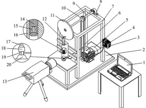
As shown in Figure 1, the testbed comprises a transmission mechanism, a crank-slider mechanism, a detection mechanism, an output mechanism, and a high-speed videographer.
In the transmission mechanism, with the rotation of the motor, the transmission shaft can be rotated by transmission belt. The motor can regulate the speed of the testbed through a frequency converter to regulate the loading force. The crank-slider mechanism comprises a rotary plate, connecting rod and sliding punch, among other parts. Nuts are ruptured through this mechanism. Detection mechanism is mainly composed of sensors. Acceleration and pressure sensors were used as the sensitive elements for measuring the parameters of shell breaking. The output mechanism is realized by computer. The output signal is transmitted to the personal computer (PC) through a data acquisition card and NI-PXI display system based on LabVIEW, and the screen displays the size of the loading force, energy and power. Using a high-speed videographer, the crack forming process can be observed as pecan shell breaking. The testbed can quantitatively measure the impact force, impact acceleration, rupture energy, power and crack forming process.
1. Computer 2. Base 3. Frequency transformer 4. Band wheel 5. Motor 6. Transmission belt 7. Rack 8. Bearing block 9. Transmission shaft 10. Pulley 11. Rotary plate 12. Connecting rod 13. High-speed camera 14. Sliding punch 15. Acceleration sensor 16. Sideway 17. Nut 18. Groove 19. Pressure sensor 20. Sensor base
2.2 Measuring principle
2.2.1 System parameters determination
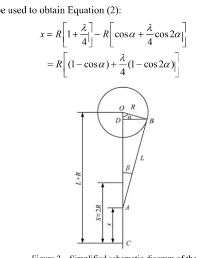
The centric crank-slider mechanism (rotary plate, connecting rod and sliding punch, among other parts) is simplified to a diagram of a crank-piston-connecting rod
mechanism. As shown in Figure 2, OB is the crank
rotation radius R, AB is length of the connecting rod L, and A is the intersection point of the piston pin and the connecting rod axis.
Given that λ=R/L, the displacement of the piston assembly could be calculated from Equation (1):
x = L + R– (Lcosβ+ Rcosα) (1) Series expansions and mathematical calculation can be used to obtain Equation (2):
1 cos cos 2
4 4
(1 cos ) (1 cos 2 )
4
x R R
R
λ α λ α
λ α α ⎡ ⎤ ⎡ ⎤ = ⎢ + ⎥− ⎢ + ⎥ ⎣ ⎦ ⎣ ⎦ ⎡ ⎤ = ⎢ − + − ⎥ ⎣ ⎦
(2)
Figure 2 Simplified schematic diagram of the crank-piston-connecting rod mechanism
As the rotary angle of the crank rotation center changes, the velocity of the piston assembly can be calculated from Equation (3):
2
sin cos sin
2
dx dx d d
V R
dt d dt dt
α λ α α α α
α
⎡ ⎤
= = ⋅ = ⎢ + ⎥
⎣ ⎦ (3)
and d
dtα ω=
where, ω is the crank angular velocity. Thus, the
velocity of the piston assembly can be calculated from Equation (4):
V (sin sin 2 )
2
R λ
ω α α
= + (4)
The maximum kinetic energy of the piston assembly
with the maximum velocity can be determined using the following formulas: 2 max 1 V 2
E= M
max (sin max sin 2 max)
2
V =ωR α +λ α
(5) The energy calculation formula is as follows:
2
1
[ (sin sin 2 )] ( . )
2 m 2 m
E= M ωR α +λ α N m
(6)
where, M is the mass of connecting rod and piston
assembly, kg; ω is the crank angular velocity, 1/s; R is the crank rotation radius, m; αm is the rotary angle at the
maximum velocity of the piston; L is the length of
connecting rod, m; and λ=R/L.
2.2.2 Determination of the impact acceleration
The impact acceleration was determined using an acceleration sensor. The acceleration signal was determined using an IEPE accelerometer, which has a small size, light mass and high bandwidth and measures the velocity signal based on the integration of the acceleration signal.
2.2.3 Determination of shell-breaking power
The shell-breaking power can be calculated using Equation (7):
p= ⋅f v (7)
where, p is the shell-breaking power, W, f is the
instantaneous impact force, N, and v is the instantaneous velocity, m/s.
2.3 Test system software design based on LabVIEW
interactive input and output controls. A block diagram is used to realize the VI logic functions of the graphical source code.
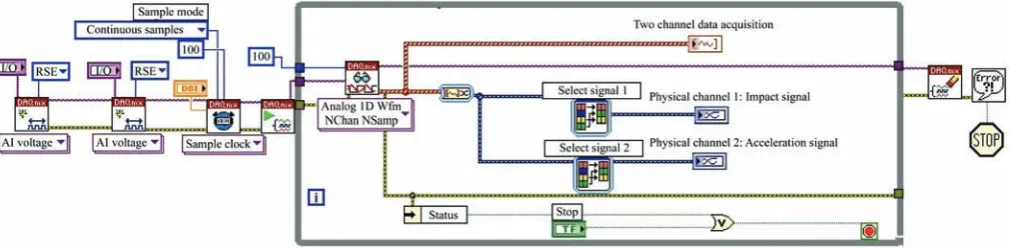
The data acquisition in this design is an important function of the data acquisition system and automatic test system based on LabVIEW. The hardware for the data acquisition system primarily comprises the following four parts: the sensor, signal conditioning equipment, data acquisition and computer. Figure 3 shows the schematic diagram of the overall system design.
Figure 3 Schematic of the testing system based on a virtual instrument
This test system requires a two-channel among analog voltage signal input, including impact signal and acceleration signal. The signals are detected by sensors and collected by data acquisition through the specified physical channel. Then these signals are converted into digital signals. Finally this information is stored and displayed in the computer. Thus, the data acquisition program is divided into the following three modules: the data acquisition and waveform display module, the data storage module and the data and waveform playback module. Data acquisition and data storage are important. The data are accurately collected and stored to provide accurate original data for
subsequent signal analysis and processing. The
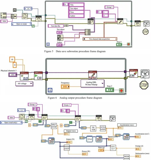
collected data are stored as a TDM streaming file. The TDM streaming file is generated using LabVIEW 8.20 improvements on a TDM file. The TDMS file data are stored in a binary manner, which is smaller and faster with the purpose of increasing the file storage speed to 600 MB/s. The manner in which these data are stored permits high speed, easy access and convenience to meet the needs of the data acquisition system storage. When the TDMS file has been completed, LabVIEW automatically generates the following two files: a *. TDMS file and a *. Tdms_index file. The former is the data file (or main file), and the latter is the index file (or header file). The major difference is that the index file does not contain raw data information, and only contains information such as attributes; thus, we can increase the speed of data retrieval and search the TDMS file. Figure 4 shows the data acquisition procedure frame diagram, and Figure 5 shows the data save subroutine procedure frame diagram.
The physical channel and sample rate are set up in the data acquisition procedure, and an intuitive data flow and data save procedure are shown in the procedure frame diagram. In the process of data storage, the test object and time will be stored in the TDMS file, and the default storage name is the current time of the test, which can subsequently query more conveniently.
The system power is derived from the motor analog output module of the data acquisition card output voltage signal to the frequency converter that controls the speed of the motor to adjust the size of the loading force. Figure 6 shows the analog output procedure frame diagram.
The impact signal and acceleration signal are shock signals with short duration (3 ms or less). The original signal of the test is expressed as the voltage signal, which is converted into digital signals through analog-to-digital conversion, and the preprocessing of the digital signal is necessary to remove the interference
signal, followed by signal analysis and calculation using the corresponding control to obtain the results. Signal analysis and calculation include the eliminate dc component, filtering, and integral subprogram. Figure 7 shows the signal analysis subroutine procedure frame diagram.
Figure 5 Data save subroutine procedure frame diagram
Figure 6 Analog output procedure frame diagram
Figure 7 Signal analysis subroutine procedure frame diagram
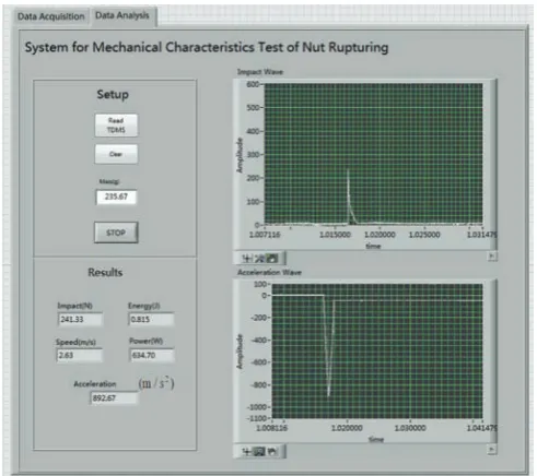
Data analysis was performed as shown in Figure 8, and the front panel, in view of the user operation and display. The open early TDMS file, a series of stored
Figure 8 Signal analysis subroutine procedure frame diagram
3 Test and results analysis
3.1 Definition of the long axis and short axis
The pecan is an oval fruit, as shown in Figure 9, the suture line orientation of the pecan is the long axis of the ellipse (X-axis), referred to as the “long axis”. The width (Y-axis) and thickness (Z-axis) are the short axes, and both are referred to as the “short axis”. Indeed, different loading orientations markedly influence the degree of kernel damage.
Figure 9 Loading orientation schematic diagram
3.2 Test materials
The present study used raw pecans collected from North Village, Tianmu Mountain, located in the Wannan area of Anhui Province at the beginning of September, which were stored in a ventilated, shady and cool test room. The pecans were divided into three groups with the following moisture contents: 9.26%, 12.82%, and 14.59%.
3.3 Test results and analysis
The pecans were tested with the appropriate moisture contents, and the results are shown in Table 1. The moisture content and the loading orientation have significant influence on the impact force, energy and power.
Table 1 Results under different moisture contents
Moisture content/%
Loading orientation
Rupture Force/N
Rupture Energy/J
Rupture Power/W
9.17
Long axis 232.825-243.173 0.947-1.161 685.426-782.843 45º 164.183-241.686 0.828-1.043 478.761-731.436 Short axis 153.652-241.289 0.721-0.997 456.1676-717.429
11.2
Long axis 176.544-244.324 0.734-0.951 568.819-710.719 45º 170.349-241.394 0.69-0.911 423.276-689.289 Short axis 175.659-242.188. 0.607-0.815 409.297-653.96
14.49
Long axis 211.762-242.645 0.712-0.94 534.462-702.1 45º 189.606-244.904 0.543-0.787 459.474-649.636 Short axis 170.013-243.103 0.624-0.865 503.666-675.317
3.4 High-speed camera recorded images
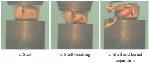
The degree of pecan shell and kernel damage was at the same loading and moisture content. The loading orientation along the long axis is shown in Figure 10. Loading from the long axis direction, broken shell cracks are extended along the pecan top to down, because in the tip, the gap between the kernel and shell is the biggest. Therefore, damage impact on pecans is the smallest.
a. Start b. Shell breaking c. Shell and kernel separation
Figure 10 Loading orientation along the long axis
The loading orientation along the short axis is shown in Figure 11. Loading from the short axis, damage of the Nuts in upper part is more serious, the lower part is complete.
a. Start b. Shell breaking c. Shell and kernel separation
The loading orientation along the 45º slant is shown in Figure 12. Loading from the 45º slant axis, damage of the Nuts in upper part is serious slightly, the lower part is complete.
a. Start b. Shell breaking c. Shell and kernel separation
Figure 12 Loading orientation along the 45º slant
Figures 10-12 show less rupture force and energy along the short axis but a high kernel-breaking rate. More rupture force and energy was required along the long axis, but the rate of kernel breaking obviously decreased, and the rupture force and energy along the 45º orientation was somewhere in the middle.
4 Conclusions
The testbed was designed through the test requirements. Through theoretical design and research in detail, the working principle of crank-slider mechanism was determined. Based on the hardware, using LabVIEW software, the test system software program was established based on the graphical programming language.
The mechanical properties of pecan were tested under different moisture contents and loading forces. The collected data of energy, power and impact load of pecan rupturing were measured and studied systematically.
The mechanical parameters (force, energy and power, etc.) for nut rupturing play a key role in the design of a shell-breaking mechanism. Accurately measuring the parameters positively affects systematic and profound studies on the shell-breaking mechanisms of walnuts or other nuts. Academics in the world have paid increasing attention to the reduction of rupture energy but neglected to maintain kernel integrity during shell breaking. Thus, studies to improve the shell-breaking rate and reduce the kernel-breaking rate provide an important theoretical basis for the optimization of shell-breaking equipment. The experimental methods and data presented here provide the basis for decreasing kernel-breaking rate.
Acknowledgments
This research was financially supported by the National Natural Science Foundation of China (Grant No. 51475002) and received strong support from the Technology Extending Stations of Ningguo, Anhui Province.
[References]
[1] Hassan-beygi S R, Aghbashlo M, Kianmehr M H, Massah J. Drying characteristics of walnut during convection drying. Intl. Agrophysics, 2009; 23(2): 129–135.
[2] Gharibzahedi S M T, Mousavi S M, Hamedi M, Rafiee S. Engineering characteristics of Persian walnut and its kernel as a function of moisture content. Proceedings of International Conference on Agricultural and Animal Science, 2010; pp.29–33.
[3] Miraliakbari H, Shahidi F. Antioxidant activity of minor components of tree nut oils. Food Chem., 2008; 111(2): 421–427.
[4] Sharifian F, Derafshi M H. Mechanical behavior of walnut under cracking conditions. Appl. Sci., 2008; 8(5): 886–890. [5] Zhao S G, Zhao Y P, Wang H X, Gao Yi, Zhang Z H, Feng D
L. Factors affecting nutshell structure of walnue. Scientia Silvae Sinicae, 2011; 47(4): 70–75.
[6] Jin F, Qin L, Jiang L, Zhu B, Tao Y. Novel separation method of black walnut meat from shell using invariant features and a supervised self-organizing map. Journal of Food Engineering, 2008; 88(1): 75–85.
[7] Qi J, Ma Q G, Yang J M, Pei D. Study on shell seal characteristics of walnut breeds in China. Nonumod Forest Research, 2009; 27(2): 57–61.
[8] Polat B, Aydin C, A B E. Some physical and mechanical properties of pistachio nut. Bulgarian Journal of Agricultural Science, 2007; 13: 237–246.
[9] Gharibzahedi S M T, Mousavi S M, Hamedi M, Khodaiyan F. Comparative analysis of new Persian walnut cultivars: nut/kernel geometrical, gravimetrical, frictional and mechanical attributes and kernel chemical composition. Scientia Horticulturae, 2012; 135(135): 202–209.
[10] Altuntas E, Özkan Y. Physical and mechanical properties of some walnut (Juglans regia L.) cultivars. International Journal of Food Engineering, 2008; 4(4): 1–14.
[11] Braga G C, Couto S M, Hara T, Neto J T P A. Mechanical behavior of macadamia nut under compression lading. Jagric Eng Res., 1999; 72(3): 239–245.
[13] Güner M, Dursun E, Dursun Í G. Mechanieal behaviour of hazelnut under compression loading. Biosystems Eng., 2003; 85(4): 485–491.
[14] Nazari G M, Mohtasebi S S, Tabatabaeefar A, Fadaei H F. Mechanical behavior of pistachio nut and its kernel under compression loading. Journal of Food Engineering, 2009; 95(3): 499–504.
[15] Ojolo S J, Damisa O, Orisaleye J I, Ogbonnaya C. Design and development of cashew nut shelling machine. Journal of Engineering, Design and Technology, 2010; 8(2): 146–157.
[16] Gharibzahedi S M T, Mousavi S M, Hamedi M, Khodaiyan F, Dadashpour A D. Mechanical behavior of Persian walnut and its kernel under compression loading: an experimental and computational study. Journal of Food Processing and Preservation, 2012; 36: 423–430.
[17] Altuntas E, Erkol M. The Effects of moisture content, compression speeds, and axes on mechanical properties of walnut cultivars. Food Bioprocess Technol, 2011; 4(7): 1288–1295.
[18] Ercisli S, Kara M, Ozturk I, Sayinci B, Kalkan F. Comparison of some physico-mechanical nut and kernel properties of two walnut (Juglans regia L.) cultivars. Not Bot Horti Agrobo, 2011; 39(2): 227–231.
[19] Zhang L H, Xu Z M, Gou W. Optimization of structure parameters of cylinder-bar type shellig device for ginkgo biloba. Transactions of the CSAE, 2012; 28(10): 39–45. (in
Chinese)
[20] Li Z X, Liu K, Yang L L, Basiti A, Ma W Q, Yan S K. Design and experiment of walnut-cracking device. Transactions of the CSAE, 2012; 43(S1): 146–152. (in Chinese)
[21] Zhang Y L, Yi Q W, Yu Q, Wang W P, Hu Z G. Structure and working principle of de-huller with multiple cutter units for lotus seeds. Transactions of the CSAE, 2008; 24(12): 76–79. (in Chinese)
[22] Cao Y H, Li C Y, Zhang Z X, Qing Y M, Yao L L. Improvement design and test to key components of castor capsule hulling device. Transactions of the CSAE, 2012; 28(18): 16–22. (in Chinese)
[23] Zhu L X, Luo X W, Liu S D. Optimized design and experiment of roller-crush board ginkgo huller. Transactions of the CSAE, 2008; 24(8): 139–142. (in Chinese)
[24] Nalawade S M, Gajakos A V, Aware A V. Design and development of hand operated cashew nut sheller. The Cashew, 2007; 21(3): 13–19.
[25] Balsubramanian D. Design, development and performance evaluation of radial arm type cashew nut sheller. AMA-Agricultural Mechanization in Asia Africa and Latin America, 2011; 42(2): 19–56.