Identifying Fire From Video Sensor Node
[1]S.R.Vijayalakshmi,
[2]S.Muruganand
[1] [2]
Department of Electronics and Instrumentation, Bharathiar University, Coimbatore-641046, Tamilnadu,
India.
[1]
[email protected]
.Abstract
:
The region of interest is captured using CCD camera and identified by smoke sensor in the wireless sensor node. The physical and dynamic characteristics and colour information of interesting region can be obtained with an application of the digital image processing algorithm. The fire source is identified according to the acquired characteristics and smoke level. The system is based on the continuous image sampling. The experimental results show that the system can accurately identify and confirm the fire. The video sensor node is designed with the sensors such as MQ2 sensor for smoke sensing, SHT75 sensor for temperature and humidity sensing, OPT101 sensor for light sensing and CCD camera. By combining sensor output with image output, the false alarm rate is zero and improves the stability. The amount of data processing can be reduced because of the use of proposed algorithm and thus shorten the execution time and storage. Alarm is activated only for fire image and fire incidents.Keywords:fire detection; fire characteristics; image process; image segmentation; smoke sensor; video sensor node;
I. INTRODUCTION
Even in this modern world, it is very difficult to detect fire in real time. Fire has sudden stochastic characteristics. Hence automatic fire monitoring, alarm and control functions are required in modern fire prevention facilities to accomplish real-time monitoring. In recent years, the remote monitoring system based on network video camera provides reliable The system is comprised of monitoring node, managing command center, wireless transmission, camera and lens, smoke sensor, console control unit and power supply system. The fire identification with the digital image processing along with smoke sensing of wireless sensor node can greatly improve the technological content and the automation level of the system, and reduce the labour intensity of personnel.
1.1 Related work
S.R.Vijayalakshmi and S.Muruganand [1] discussed about the real time monitoring of wireless fire detection node. M. Morin at.el [2] analyzed about the computer-supported visualization of rescue operations. Xue-gui Wan at.el [3] analyzed about the novel conceptual fire hazard ranking distribution system based on multisensory Technology. Konstantinous at.el [4] dealt about an automated fire detection and alerting application based on satellite and wireless communications. Fatih Erden at.el [5] discussed about the wavelet based flickering flame detector using differential PIR sensors.
This paper is organized as follows. Section 2 provides the proposed algorithms for flame and fire image processing. Section 3 explains about its results and discussion. Section 4 gives about the conclusion and further work.
II. IMAGE PREPROCESSING
2.1The physical characteristics of fire
analyzed in the sections such as image segmentation, binarization and expansion, noise processing and eliminating, edge detection, peak flame identification and so on.
2.2 Image Segmentation
Image segmentation plays a very important role in image processing. The image segmentation results affect the image of follow-up processing directly. It divide image space into some significant areas according to some characteristics such as gray, spectrum and texture. Classical image segmentation algorithm such as iteration, threshold, segmentation, maximum between cluster variance, the maximum entropy threshold method are entirely depend on gray image which result in the loss of colour characteristic of image. Due to this weakness, a new segmentation algorithm based on the colour characteristic of the image is presented and proposed along with smoke detecting sensor. It can divide and get the flame target better. Most colourful models used today are hardware and application-oriented. In digital image processing, the most common model belong to hardware-oriented is RGB (red, green, and blue) model which is mainly used in colour monitor and a large class of colour video camera. HSI (Hue/tonal, saturation and Intensity/brightness) model is more suitable and explain the colour. It also can divide the image information into colour and gray to make it easier to apply gray processing technology. The algorithm presented here will use both RGB and HSI models. Firstly, HSI format should be converted into RGB format because the images are all BMP images. Each component has a conversion formula as follows in equation 1:
;
;
---(equation 1)
After getting the HSI values of the image pixel B > G if H unchanged, B < G if H=360-H,and B=G if H=360 are judged. The H values of the flame are within specific range, only by which the flame target cannot be extracted from the source image accurately. Hence the RGB image segmentation model should be combined with the image segment. To determine whether the colour images are in red, the following steps are followed in the algorithm. Its steps are based on 1) Get the three RGB color components; 2) To determine whether the largest component of that is the red component, that is, R> G, R> B; 3) To determine whether the value of the red component has reached a certain amount, that is, R> r (r is the set threshold); 4) Whether the red points are obviously much larger than the second largest value in comparison (That is, R>> G, R>> B).
2.2.1 Binarization
Binarization image processing are areas of image segmentation. A lot of energy is released when flame is burning. This is shown in the image as a high value of image pixel gray. So a suitable threshold can be chosen and method of fetching 1 out of nonzero element is chosen. The effect is good and the execution time is reduced.
2.2.2 Expansion
In the combustion process, the uneven distribution of the ambient air results incomplete combustion flame in some areas. In that image region the red component is not obvious or not enough brightness. This creates faults and fracture zone in the flame images. To reduce this expansion is suggested. So that it strengthens the border and eliminate fault and broken link in the images.
2.3 Noise Processing
The image quality is decreased with the loss of information in the manmade processing. The noise in the image acquisition process affects identifying the characteristics of fire at later stages. Therefore different kind of noise such as salt pepper are introduced. After that the degraded images need to be smoothed with the median filter method. It is a non-linear approach used to remove noise. It retains good image details. The median filter is based on replacing the value in digital images with the median value of each point value in neighbour of the point. This filter introduces good distribution of the images on the elimination of all kinds of random noises and also fuzzy edges. Small white areas found in the observed image. This is because of scattering of beam caused by smoke. To eliminate these noises, black and white noise cancellation and noise reduction are used.
2.4 Edge Detection
;
---( equation 2)
2.4.1 Identification of the Peak Flame
The edge of the flame will be made into chain code first. To normalize the chain code, circulary shift the chain code to get the smallest and select the first order differential. When the chain code in a certain step takes on an effective rise and fall, a cusp can be obtained. Flame region closed contour collection can be expressed in equation 3 as follows:
---( equation 3);
is the studied region of the suspicious pixels set; is the region on the edge pixels, if the point on the curve there is a sharp point, then the following relations equation 4:
; --- (equation 4) ; θ is the angle between two vector functions; is the angle value which is set.
2.5 Flame Colour Algorithm based on distribution
For flame center to outer, its colour mobiles from white to yellow to red generally. The sun, light source of interference does not change its colour. The pixel value does not change significantly for the sun in the image. According to the physical characteristics of fire, recognition algorithm is proposed as follows. First, check all the suspected objects flame pixel values. Then calculate each pixel value of the proportion of red as in the formula 5:
--- (equation 5)
is the image of three-component red ,green and blue and then withthat calculating the red pixel value of the variance of the proportion. When the suspicious target is flame means the red side of the margin has larger proportion. When the suspected target of the interference sources such as the sun, lighting, etc., the colour did not change significantly and pixel values remained near the average in a volatile. So the red pixel value of the variance of the proportion is small and close to zero. The steps of algorithm implementation are as follows in equation 6:
Read the suspected flame part of the image pixel value f (x, y) , then storage them into the array; Pixel array for the mathematical expectation r = E( f (x, y)) ;
Pixel array for the variance c = E( f (x, y) − r)2; ---(equation 6)
2.6 Flame Algorithm Based on Dynamic Characteristics
Flame is the main body of fire. In the collection of flame images the fire is a bright area. So, it is necessary to figure out the flames from the light and understand the irregular changing in the bright areas. The shape of the flame is irregular and changes arbitrarily. But there is a feature of the flame in that some bright areas overlapping but cannot be completely overlapping in two of the suspicious image acquired. When a suspicious light is found named A collect images and use the above rules to determine the rules of suspicious B in bright area. Principle: If A, B overlapping windows 0.1 or 0.8, then it is not the flame. Overlap rate is the overlap part between window B and window A with a value of 1 in accounting for overlap the rate of 1 point. overlap rate 0.1 is mainly for mobile sources and interference with the light sources. overlap 0.8 is mainly directed against monitoring of lighting equipments in the region. In the monitoring region using of lighting equipments, the bright window both appear in two adopted images but when comparing the two, they do not entirely overlap. Thus, the two overlap rate 80% and it is not a fire which is ruled out as only a possibility of interference of fixed lighting equipment. The sun can be considered as the second situation.
2.7 Smoke Sensor
Along with the CCD camera, smoke sensor also interfaced in the video node. The smoke level is compared in some cases to detect fire. If smoke level exceeds the threshold level, image processing steps are carried out to determine the occurrence of fire.
III. RESULT AND ANALYSIS
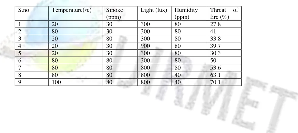
response time and no need to change the network bus. The system reduces the false alarm rate and improves the stability by using the temperature and smoke sensors in the node. Alarm is activated only for fire image and fire incidents. The video sensor node is as shown in figure 2. The video sensor node is designed with the sensors such as MQ2 sensor for smoke sensing, SHT75 sensor for temperature and humidity sensing, OPT101 sensor for light sensing and CCD camera. All the sensors are interfaced with the microcontroller with minimum interfacing components. XBeePro transceiver IC is interfaced with the microcontroller for transmitting and receiving information to and from the control station. The table 1 shows the smoke sensor output to combined with image to detect fire. So the false alarm rate is zero.
Figure 2. Video sensor node
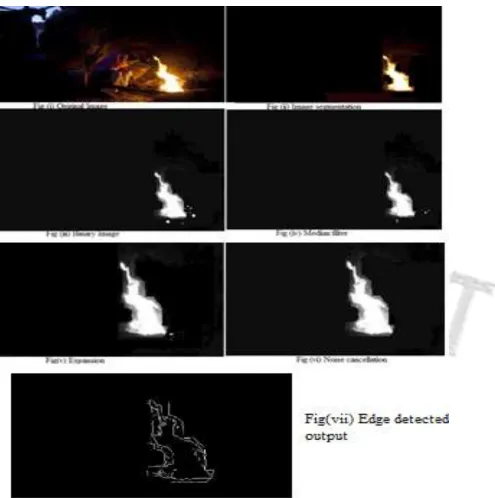
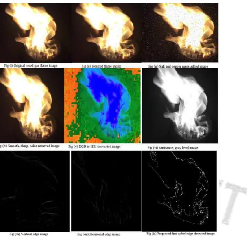
Before doing this image processing steps the smoke sensor node output is checked for the fire risk level. after doing image processing work it is compared and final decision is taken if it exceeds the threshold level. The figure 1 shows steps in the algorithms. The figure 3 shows the proposed algorithm technique step images and final output image. The fire risk percentage is compared with the output image for the fire alarm activation. The false rate is zero when compared with smoke sensing process.
Table 1.Evaluation results of smoke sensor system using fuzzy logic
S.no Temperature(◦c) Smoke (ppm)
Light (lux) Humidity (ppm)
Threat of fire (%)
1 20 30 300 80 27.8
2 80 30 300 80 41
3 20 80 300 80 33.8
4 20 30 900 80 39.7
5 20 30 300 80 30.3
6 80 80 300 80 50
7 80 80 800 80 53.6
8 80 80 800 40 63.1
Figure 3. Proposed algorithm technique step images and final output image
VI. CONCLUSION
Acknowledgment
This work is supported by the University Grants Commission, Government of India under grant no. F.151/2014-15/PDFWM-2014-15-OB-TAM-24657
REFERENCES
1. S.R.Vijayalakshmi and S.Muruganand, "Real Time Monitoring of Wireless Fire Detection Node", Elsevier Procedia Technology 24 ( 2016 ) pp. 1113 – 1119 .
2. M. Morin at.el , "Computer-supported visualization of rescue operations", Safety Science, Vol.35, 2000, pp. 3-27. 3. Xue-gui Wan at.el , "A Novel Conceptual Fire Hazard Ranking Distribution System based on Multisensory
Technology", Science Direct, Procedia Engineering, Vol.71, 2014, pp.567 – 576.
4. Konstantinous at.el, "An Automated Fire Detection and Alerting Application based on Satellite and Wireless Communications", 2010 5th Advanced Satellite Multimedia Systems Conference and the 11th Signal processing for space communications workshop.
5. Fatih Erden at.el, "Wavelet based flickering flame detector using differential PIR sensors", Fire Safety Journal Vol.53, 2012, pp.13–18.
Authors:
S.R.Vijayalakshmi * is a Post Doctoral research Fellow in Department of Electronics and Instrumentation in Bharathiar University. She received her B.Sc. M.Sc. M.Phil. and Ph.D in Electronics from the Bharathiar University and also received M.Sc. and M.Phil. in Computer Science from Avinashilingam University. She has 20 years of experience in the teaching and also in research. Her research interests include digital image processing, embedded systems, and wireless sensor networks. She completed one DST-WOS-A project funded by Government of India. (* corresponding author). She is an author of two books.