Enterprise Communications Server
Release 8.3
plete and accurate at the time of printing. However, information is subject to change.
Lucent Technologies Web Page
The world wide web home page for Lucent Technologies is: http://www.lucent.com
Preventing Toll Fraud
“Toll fraud” is the unauthorized use of your telecommunications system by an unauthorized party (for example, a person who is not a corporate employee, agent, subcontractor, or working on your company’s behalf). Be aware that there may be a risk of toll fraud associated with your system and that, if toll fraud occurs, it can result in substantial additional charges for your telecommunications services.
Lucent Technologies Fraud Intervention
If you suspect you are being victimized by toll fraud and you need technical support or assistance, call the appropriate BCS National Customer Care Center telephone number. Users of the MERLIN®, PARTNER®, and tem 25 products should call 1 800 628-2888. Users of the System 75, Sys-tem 85, DEFINITY® Generic 1, 2 and 3, and DEFINITY® ECS products should call 1 800 643-2353.
Providing Telecommunications Security
Telecommunications security (of voice, data, and/or video communications) is the prevention of any type of intrusion to (that is, either unauthorized or malicious access to or use of your company’s telecommunications equip-ment) by some party.
Your company’s “telecommunications equipment” includes both this Lucent product and any other voice/data/video equipment that could be accessed via this Lucent product (that is, “networked equipment”).
An “outside party” is anyone who is not a corporate employee, agent, sub-contractor, or working on your company’s behalf. Whereas, a “malicious party” is anyone (including someone who may be otherwise authorized) who accesses your telecommunications equipment with either malicious or mischievous intent.
Such intrusions may be either to/through synchronous (time-multiplexed and/or circuit-based) or asynchronous (character-, message-, or packet-based) equipment or interfaces for reasons of:
• Utilization (of capabilities special to the accessed equipment) • Theft (such as, of intellectual property, financial assets, or
toll-facil-ity access)
• Eavesdropping (privacy invasions to humans)
• Mischief (troubling, but apparently innocuous, tampering) • Harm (such as harmful tampering, data loss or alteration, regardless
of motive or intent)
Be aware that there may be a risk of unauthorized intrusions associated with your system and/or its networked equipment. Also realize that, if such an intrusion should occur, it could result in a variety of losses to your company (including, but not limited to, human/data privacy, intellectual property, material assets, financial resources, labor costs, and/or legal costs).
Your Responsibility for Your Company’s Telecommunications Security The final responsibility for securing both this system and its networked equipment rests with you – a Lucent customer’s system administrator, your telecommunications peers, and your managers. Base the fulfillment of your responsibility on acquired knowledge and resources from a variety of sources including but not limited to:
• Installation documents • System administration documents • Security documents
• Hardware-/software-based security tools • Shared information between you and your peers • Telecommunications security experts
To prevent intrusions to your telecommunications equipment, you and your peers should carefully program and configure your:
• Lucent-provided telecommunications systems and their interfaces • Lucent-provided software applications, as well as their underlying
hardware/software platforms and interfaces
• Any other equipment networked to your Lucent products
cial environment. This equipment generates, uses, and can radiate radio-fre-quency energy and, if not installed and used in accordance with the instructions, may cause harmful interference to radio communications. Operation of this equipment in a residential area is likely to cause harmful interference, in which case the user will be required to correct the interfer-ence at his own expense.
Part 68: Answer-Supervision Signaling. Allowing this equipment to be operated in a manner that does not provide proper answer-supervision sig-naling is in violation of Part 68 Rules. This equipment returns answer-supervision signals to the public switched network when:
• Answered by the called station • Answered by the attendant
• Routed to a recorded announcement that can be administered by the CPE user
This equipment returns answer-supervision signals on all DID calls for-warded back to the public switched telephone network. Permissible excep-tions are:
• A call is unanswered • A busy tone is received • A reorder tone is received
Industry Canada (IC) Interference Information
This digital apparatus does not exceed the Class A limits for radio noise emissions set out in the radio interference regulations of Industry Canada.
Le Présent Appareil Nomérique n’émet pas de bruits radioélectriques dépassant les limites applicables aux appareils numériques de la class A préscrites dans le reglement sur le brouillage radioélectrique édicté par le Industrie Canada.
Trademarks
See the preface of this document.
Ordering Information
Call: Lucent Technologies BCS Publications Center
Voice 1 800 457-1235 International Voice +1 317 322-6791 Fax 1 800 457-1764 International Fax +1 317 322-6699 Write: Lucent Technologies BCS Publications Center
2855 N. Franklin Road Indianapolis, IN 46219 USA
For additional documents, refer to the section in “About This Document” entitled “Related Resources.”
You can be placed on a standing order list for this and other documents you may need. For more information on standing orders, or to be put on a list to receive future issues of this document, contact the Lucent Technologies Publications Center.
Obtaining Products
To learn more about Lucent Technologies products and to order products, contact Lucent Direct, the direct-market organization of Lucent Technolo-gies Business Communications Systems. Access their web site at www.lucentdirect.com. Or call the following numbers: customers 1 800 451 2100, account executives 1 888 778 1880 (voice) or 1 888 778 1881 (fax).
European Union Declaration of Conformity
The “CE” mark affixed to the equipment means that it conforms to the above directives. Lucent Technologies Business Communications Systems declares that XXX equipment specified in this document conforms to the referenced European Union (EU) Directives and Harmonized Standards listed below:
EMC Directive 89/336/EEC Low-Voltage Directive 73/23/EEC
Comments
To comment on this document, return the comment card at the front of the document.
Acknowledgment
DEFINITY R8.3 Feature Overview 1
Network Call Redirection 1
IP Media Processor Interface for VoIP Bearer (TN2302AP) 1
ARS/AAR Dialing without FAC 2
CVM Enhancements 2
24-Port Analog with Caller ID 2
Upgrading R8.1/8.2 to R8.3 3
Read This First 3
Service Interruption 3
Call Management System (CMS) 3
Contact Network Technicians 3
Translation Card Compatibility (si/csi only) 4
Software Upgrade 4
Required Tools 4
Required Hardware 5
DC Isolator 5
Antistatic Protection 5
Task Table 6
Upgrade the Software 7
Check SPE 7
Resolve Alarms 8
Back Up Disk (r only) 8
Disable Scheduled Maintenance and Alarm
Origination to INADS 8
Disable TTI 9
Check TTI Status 9
Check Link Status 9
Save Translations 9
Save Announcements (if necessary) 10
Verify Software Version 10
Resolve Alarms 11
Save Translations (r only) 11
Save Announcements (r only) 11
Restore Disk (r only) 11
Upgrade Software (csi only) 12
Upgrade Software (si only) 12
Check SPE status (si, H/C only) 14
Reset SPE status (r, H/C only) 14
Set Daylight Savings Rules 15
Set Date and Time 16
Verify Software Version (si, r only) 18
Verify Additional Administration 18
Set Core Dump Vector (r only) 18
Enable TTI 18
Enable Scheduled Maintenance 19
Enable Customer Options and Alarm Origination 19
Resolve Alarms 20
Check Link Status 20
Save Translations 20
Restore Announcements (csi/si only) 20
Save Announcements (r only) 20
Back Up Disk (r only) 21
Return Replaced Equipment 21
Where to Call for Technical Support 22
IP Solutions 23
Preparing for Installation and Upgrade 23
Check your onsite equipment 24
Check your shipment 25
Installing the TN2302AP IP Media Processor 26
Connect the cables for TN799B 26
Connect the cables for TN2302AP 27
Connect the Ethernet 27
Install the Circuit Packs 27
Initial Administration Steps for C-LAN and
IP Media Processor 29
Test the External Connection to the LAN 31 Upgrading TN802 IP Trunking to TN2302AP IP
Media Processor 32
Pre-upgrade steps 32
Remove the Circuit Packs 32
Replace the Cables 33
Install the circuit packs 33
Upgrading a TN802B IP Interface Assembly to
TN2302AP IP Media Processor 34
Pre-upgrade steps 34
Remove the Circuit Packs 35
Replace the Cables 35
Install the circuit packs 36
Administration Steps 36
Modified Maintenance Objects 37
ISDN-SGR (ISDN-PRI Signaling Group) 37
ISDN-TRK (DS1 ISDN Trunk) 37
TIE-DS1 (DS1 Tie Trunk) 38
New Maintenance Objects 39
IPMEDPRO (IP Media Processor Circuit Pack) 39
Error Log Entries and Test to Clear Values 40 System Technician-Demanded Tests: Descriptions
and Error Codes 44
Control Channel Looparound Test (#52) 45
SAKI Sanity Test (#53) 46
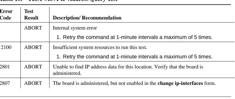
IP Address Query Test #1371 47
Ping Test (#1379) 48
MP Diagnostic Test (#1406) 50
MEDPRO (Media Processor MAPD Circuit Pack) 53
Error Log Entries and Test to Clear Values 54 System Technician-Demanded Tests: Descriptions
and Error Codes 57
Control Channel Looparound Test (#52) 58
SAKI Sanity Test (#53) 59
IP Address Query Test #1371 60
Ping Test (#1379) 61
NT Reset Test (#1381) 63
NIC Query Test (#1383) 65
MEDPROPT (TN802/TN2302 MED PRO DSP PORT) 66
Error Log Entries and Test to Clear Values 66 System Technician-Demanded Tests: Descriptions
and Error Codes 68
DSP Capacity Query Test (#1382) 68
DEFINITY R8.3 Feature Overview
The primary focus of Release 8.3 is the call center Network Call Redirection feature. In addition, R8.3 introduces the new IP Media Processor circuit pack, enhances the Centralized Voice Messaging feature, and adds a limited version of ARS/AAR Dialing without FAC.
This introduction covers the following topics:
• Network Call Redirection • IP Media Processor
• ARS/AAR Dialing without FAC
• Centralized Voice Messaging using Mode Codes Enhancements • TN793B/2793B 24 Port Analog Circuit Pack with Caller Identification
Network Call Redirection
Network Call Redirection (NCR)
allows customers to reduce the number of ISDN trunks required by having the PSTN re-direct incoming ISDN calls to another PSTN destination.Call Center customers will no longer require trunk-to-trunk connections for Interflow, ASAI, or station/agent/VRU transferred calls.
Call redirection is invoked in real time on a call-by-call basis.
NCR utilizes either the ETSI Network Call Deflection (NCD) or ANSI Network Call Transfer (NCT) features provided by the PSTN.
IP Media Processor Interface for VoIP Bearer
(TN2302AP)
TN2302AP is a hardware alternative to TN803B MedPro.
The first release of the TN2302AP, available in July, 2000, is intended for configurations that require IP station and trunk connectivity without fax. Future releases of this circuit pack will support fax using R8.3 and later DEFINITY Software.
TN2302AP has
the following features:• Variable packet sizing (10-30 ms).
• Support for new 46xx series Ethernet telephones with US transmission parameters downloads.
• Board that includes 10/100 BaseT Ethernet interface.
• Echo cancellation, silence suppression, DTMF detection, and conferencing.
ARS/AAR Dialing without FAC
ARS/AAR Dialing without FAC allows a DEFINITY system to be administered so that callers can place Automatic Route Selection (ARS) and/or Automatic
Alternate Routing (AAR) calls without first dialing the Feature Access Code (FAC). This is the only approved and supported capability. ARS/AAR Dialing without FAC is not to be used or sold to meet any other need.
This feature is not generally available in R8.3. Only select customers will be granted authorization to purchase it under a Controlled Availability status.
It is strongly recommended that systems with the ARS/AAR dialing without FAC feature active do not activate transfer out of the voice mail system. Additionally, other adjuncts should be checked to verify that calls will not be allowed off-switch
unintentionally.
CVM Enhancements
Release 8.3 updates the Centralized Voice Messaging using Mode Codes feature to work with Merlin Legend. For more information on CVM, refer to the LVI courses BTT705B and BSS203B, and to Appendix B in Administration for Network Connectivity, 555-233-504.
24-Port Analog with Caller ID
The 24-Port Analog circuit pack with caller ID was introduced in R8.2. Features include:
• New board codes are TN793B and TN2793B.
• Customers can receive Caller ID information on Analog Phones.
• 24 analog ports that can be used for Bellcore compliant Caller ID capable devices such as Caller ID boxes or telephones.
Caller ID Information will include:
• Telephone Number, if sent by Central Office.
Upgrading R8.1/8.2 to R8.3
This section provides the information to upgrade from a DEFINITY ECS Release 8.1 or Release 8.2 to a DEFINITY ECS Release 8.3 as a software upgrade only.
To upgrade from pre-Release 8.1 to Release 8.3, refer to one of the following books:
• DEFINITY Enterprise Communications Server Release 8 Installation, Upgrades, and Additions for Compact Modular Cabinets
• DEFINITY Enterprise Communications Server Release 8 Upgrades and Additions for R8si
• DEFINITY Enterprise Communications Server Release 8 Upgrades and Additions for R8r
Read This First
Service Interruption
The upgrade process requires a service interruption of about 10 minutes for a standard reliability and must be closely coordinated with the customer and the local account team.
Call Management System (CMS)
The CMS link is dropped and restarted during the upgrade. This causes CMS data to be lost. This data loss can be minimized if the upgrade is performed just after the last CMS measurement interval.
All measurement data is lost during the upgrade (including BCMS). If needed, the reports may be printed before the upgrade begins.
CMS could abort the processing of a call if a measured trunk that was part of the conference dropped off the call before the end of the call.
Contact Network Technicians
Translation Card Compatibility (si/csi only)
Release 8.1 or 8.2 formatted translation cards are compatible with Release 8.3 systems and, therefore, can be reused. It is not necessary to obtain new Release 8.3 formatted translation cards.
Software Upgrade
Although the translations upgrade automatically to Release 8.3, several features require special attention because of screen changes or potential naming conflicts in the update or upgrade procedure.
Between customer confirmation and the actual update or upgrade, check the screens to ensure the translations meet the customer’s needs. After rebooting the system, enter the translations either locally or remotely. If done remotely, Contact Field Support Administration Center (FSAC) for the remote entry. For information to make the required changes, refer to:
• DEFINITY Enterprise Communications Server Release 8 Administrator’s Guide
No administration changes should be made during the upgrade procedure. There can be time gaps between steps and, since the system cannot prevent
administration changes, it is up to the system technician to make sure that none are attempted during the entire upgrade process.
Required Tools
This upgrade requires one copy of each of the following books:
• DEFINITY Enterprise Communications Server Release 8 Maintenance for R8si
• DEFINITY Enterprise Communications Server Release 8 Maintenance for R8csi
• DEFINITY Enterprise Communications Server Release 8 Maintenance for R8r
Required Hardware
Ensure that the following items are available before proceeding:
DC Isolator
Each peripheral connected to a DC-powered system by the asynchronous EIA RS-232 interface requires a 116A or 105C isolator. The isolator is inserted at the RS-232 interface between the peripheral and the interface connector to isolate ground between the system and external adjuncts.
Antistatic Protection
!
CAUTION:
When handling circuit packs or any components of a DEFINITY ECS system, always wear an antistatic wrist ground strap. Connect the strap to an approved ground such as ground jack on the DEFINITY ECS system.
Comcode Description Quantity
406805481 Release 8.3 Generic Program Card (csi) 1 601810790 Release 8.3 Generic Program Card (si) 1 J58890TO-1 L1
or
J58890TF-1 L1
Release 8.3 Removable Media (r only) 2 (4 if duplex)
csi only:
601845589 or
601845571 or
601845563
2-Mbyte Mass-Storage Translation Card (White Card) or
4-Mbyte Mass-Storage Translation Card (White Card) or
10-Mbyte Mass-Storage Translation Card (White Card)
11
1. A 4-Mbyte translation card is required for a system with recorded announcements. A 10-Mbyte translation card is required if a DEFINITY Wireless Business System is installed.
si only:
601817448 or
601817422 or
601817430
2-Mbyte Mass-Storage Translation Card (White Card) or
4-Mbyte Mass-Storage Translation Card (White Card) or
10-Mbyte Mass-Storage Translation Card (White Card)
Task Table
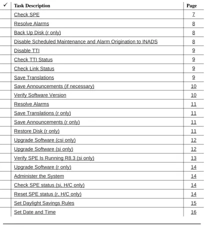
Table 1 provides the high-level tasks to perform the upgrades in this chapter. Refer to the appropriate page for instructions for each step. The upgrade
procedure is similar for both the standard and high or critical reliability system with a few exceptions. These exceptions are noted as you go through the steps.
Table 1. Tasks to upgrade the software
á
Task Description PageCheck SPE 7
Resolve Alarms 8
Back Up Disk (r only) 8
Disable Scheduled Maintenance and Alarm Origination to INADS 8
Disable TTI 9
Check TTI Status 9
Check Link Status 9
Save Translations 9
Save Announcements (if necessary) 10
Verify Software Version 10
Resolve Alarms 11
Save Translations (r only) 11
Save Announcements (r only) 11
Restore Disk (r only) 11
Upgrade Software (csi only) 12
Upgrade Software (si only) 12
Verify SPE Is Running R8.3 (si only) 13
Upgrade Software (r only) 14
Administer the System 14
Check SPE status (si, H/C only) 14
Reset SPE status (r, H/C only) 14
Set Daylight Savings Rules 15
Upgrade the Software
Check SPE
For csi/si:
1. Type status system1 and press Enter to check the health of the system.
For r:
1. Type status spe and press Enter to check the health of the SPE.
For high or critical reliability systems:
• TheStandby Refreshed field shows yes • TheStandby Shadowing field shows on • TheStandby Handshake field shows up
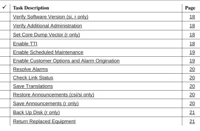
Verify Software Version (si, r only) 18
Verify Additional Administration 18
Set Core Dump Vector (r only) 18
Enable TTI 18
Enable Scheduled Maintenance 19
Enable Customer Options and Alarm Origination 19
Resolve Alarms 20
Check Link Status 20
Save Translations 20
Restore Announcements (csi/si only) 20
Save Announcements (r only) 20
Back Up Disk (r only) 21
Return Replaced Equipment 21
Table 1. Tasks to upgrade the software — Continued
á
Task Description PageResolve Alarms
1. Type display alarms and press Enter to examine the alarm log. Resolve any alarms that may exist using
• DEFINITY Enterprise Communications Server Maintenance for R8csi.
• DEFINITY Enterprise Communications Server Maintenance for R8si.
• DEFINITY Enterprise Communications Server Maintenance for R8r.
Back Up Disk (r only)
1. Type backup disk and press Enter to write all information from the disk to the backup removable media. This takes 30 to 40 minutes.
2. Remove the removable media from the optical drive.
Disable Scheduled Maintenance and Alarm
Origination to INADS
NOTE:
Make sure scheduled daily maintenance does not interfere with the upgrade.
1. Type change system-parameters maintenance and press Enter to prevent scheduled daily maintenance from interfering with the update or upgrade.
2. If scheduled maintenance has begun, set the Stop Time field to 1 minute after the current time.
or
If scheduled maintenance has not begun, set the Start Time field to a time after the upgrade is completed. For example, if you start the upgrade at 8:00 p.m. and the upgrade takes 90 minutes, set the Start Time field to 21:30.
!
CAUTION:
If you do not disable Alarm Origination, the system may generate alarms, resulting in unnecessary trouble tickets.
3. Type neither in the Alarm Origination to OSS Numbers field and press Enter.
NOTE:
Disable TTI
NOTE:
Do this step only if the Terminal Translation Initialization (TTI) is enabled.
!
CAUTION:
If you do not disable the TTI, the translations can be corrupted.
1. Type change system-parameters features and press Enter.
2. On the second screen, set the TTI Enable? field to n to de-activate the TTI feature.
Check TTI Status
1. Type status tti and press Enter. Wait until the Percent Complete field shows 100%.
Check Link Status
This optional step is to make sure the links are in service before and after the upgrade.
1. Type display communication-interface links and press Enter. Write down all enabled links.
2. Type status link number and press Enter for each enabled link.
3. Write down which links are in service.
Save Translations
1. Type save translation and press Enter.
For csi/si, the command writes all translations from memory to the original translation flashcard, which takes about 10 minutes.
For r, the command writes all translations from memory to the system disk, which takes about 2 minutes.
When the save translations is successful, the error code is a zero; otherwise, the translations are not copied. If the translations were corrupted, the following error message displays when logging in:
NOTE:
The save translation command cannot function if translations are corrupt.
Save Announcements (if necessary)
NOTE:
The TN750C Announcement circuit pack stores announcements in nonvolatile memory; saving the announcements is optional.
1. If the PPN contains a TN750/B Announcement circuit pack, type display announcements and press Enter.
2. If administered recorded announcements are listed, type save announcements cabinet carrier slot and press Enter. For example, 01D03. This takes about 30 minutes.
NOTE:
For some software loads, type save announcements from cabinet carrier slot. Type help and press Enter for complete command syntax.
Verify Software Version
For csi/si:
1. Type list configuration software-version and press Enter. Under the
UPDATE FILE column, note whether a patch has been applied.
NOTE:
If the system must be restored to the old software, this patch must be downloaded onto the system.
For r:
NOTE:
The Tape Resident field shows the software load number. Write it down for use later.
If standard reliability:
1. Type list configuration software-version and press Enter to verify that the removable media or contains the Release 8 software.
If high or critical reliability (si/r only):
Resolve Alarms
• Type display alarms and press Enter to examine the alarm log. Resolve any alarms that may exist using
• DEFINITY Enterprise Communications Server Maintenance for R8csi. • DEFINITY Enterprise Communications Server Maintenance for R8si. • DEFINITY Enterprise Communications Server Maintenance for R8r.
Save Translations (r only)
1. Type save translations removable-media and press Enter to save translations to the new removable media, which takes about 2 minutes.
Save Announcements (r only)
1. Type save announce removable-media and press Enter to save announcements to the new removable media.
Restore Disk (r only)
If standard reliability:
1. Type restore disk full and press Enter to write the new software to disk. Release 8 system software is now resident on the disk.
If high or critical reliability:
1. Type restore disk full both and press Enter to write the new software to disk.
NOTE:
Upgrade Software (csi only)
1. Insert the Release 8.3 generic program card (orange card) into the TN798B processor circuit pack.
2. Type upgrade software and press Enter to load the software.
3. When prompted, replace the orange card with the original translation card. When the login: prompt appears, the software is loaded onto the processor board.
If the translations were corrupted, the following error message displays when logging in:
!
WARNING:
Translation corruption detected; call Lucent distributor immediately.
NOTE:
The save translation command cannot function if the translation corruption message appears.
Upgrade Software (si only)
For standard reliability:
!
CAUTION:
All calls are dropped—this is a service interruption.
1. Insert the Release 8.3 generic program card (orange card) into the TN794 NetPkt circuit pack.
2. Type list configuration software-version and press Enter to verify that the system is running the updated release.
3. Type upgrade software and press Enter. The system loads the Release 8.3 software.
For high or critical reliability:
!
CAUTION:
All calls are dropped—this is a service interruption.
1. Replace the translation card in the standby SPE with the generic program (orange) flashcard.
2. Type upgrade software and press Enter. The system loads the Release 8 software.
3. When prompted, replace the generic program (orange) card with the original translation card; and replace the translation card in the active SPE with the generic program (orange) card.
4. When prompted, replace the generic program (orange) card with the original translation card. When the login: prompt appears, the software and translations are loaded onto the TN790B processor boards.
Verify SPE Is Running R8.3 (si only)
For standard reliability:
1. Log in as craft at the login: prompt.
2. Type list configuration software-version and press Enter to verify that the system is running the updated release.
For high or critical reliability
1. Log in as craft at the login: prompt.
2. Type list configuration software-version long and press Enter to verify that the system is running the updated release on both SPEs.
If you cannot access the SPE:
3. Type status system 1 to verify the standby SPE is in the standby mode.
4. If the system is not in the standby mode:
a. Type busyout spe-standby and press Enter.
b. Type refresh spe-standby and press Enter
c. Type release spe-standby and press Enter
d. Type status system 1 and press Enter to verify that the standby SPE is in the standby mode.
Upgrade Software (r only)
This command copies the software from the removable media to the system disk and takes about 15 minutes to complete.
For standard reliability:
!
CAUTION:
All calls are dropped—this is a service interruption.
1. Type upgrade software G3V8r.xx.x.xxx.x (entire alphanumeric string of new software version) and press Enter. At the prompt, press Enter to save translations.
For high or critical reliability:
1. Type upgrade software G3V8r.xx.x.xxx.x no-calls (entire alphanumeric string of new software version) and press Enter. At the prompt, press Enter to save translations and attempt to preserve calls across the interchange.
Administer the System
1. After the system resets, log in as craft.
2. Check for the Translation Corruption Detected message before proceeding with the upgrade.
!
CAUTION:
Do not continue with the upgrade process until the translations errors are corrected.
Check SPE status (si, H/C only)
1. Type status system 1 and press Enter to check the SPE Alarms field and verify that the Tone Clock is active.
Reset SPE status (r, H/C only)
1. Type status SPE and press Enter. Wait until the Standby Handshake field displays up, which takes about 3 minutes.
2. Type reset spe-standby 4 and press Enter.
NOTE:
Set Daylight Savings Rules
You can set up to 15 customized daylight savings time rules. If you have cabinets in several different time zones, you can set up rules for each on a location basis. A daylight savings time rule specifies the exact time when you want to transition to and from daylight savings time. It also specifies the increment at which to transition.
NOTE:
The default daylight savings rule is 0, no daylight savings.
1. Type change daylight-savings-rules and press Enter.
2. Type the appropriate start and stop information in the Change Day,
Month, Date, Time, and Increment fields for each rule (for example, 1:00 equals one hour) .
NOTE:
You can change any rule except rule 0 (zero). You cannot delete a daylight savings rule if it is in use on either the Locations or Date and Time screens.
When done, press Enter. The Locations screen is automatically populated from the Daylight Savings Rules screen entries. No Set Locations needed in Release 7 and later.
DAYLIGHT SAVINGS RULES
Rule Change Day Month___Date Time____Increment
0: No Daylight Savings
1: Start: first Sunday___ on or after April___ 1 at _2:00 01:00
Stop: first Sunday___ on or after October_ 25 at _2:00
2: Start: first _________ on or after ________ __ at __:__
Stop: first _________ on or after ________ __ at __:__
3: Start: first _________ on or after ________ __ at __:__
Stop: first _________ on or after ________ __ at __:__
4: Start: first _________ on or after ________ __ at __:__
Stop: first _________ on or after ________ __ at __:__
5: Start: first _________ on or after ________ __ at __:__
Stop: first _________ on or after ________ __ at __:__
6: Start: first _________ on or after ________ __ at __:__
Stop: first _________ on or after ________ __ at __:__
7: Start: first _________ on or after ________ __ at __:__
Set Date and Time
1. Type set time and press Enter to bring up the Date and Time screen.
Screen 1. Typical Date and Time Screen
2. Type the day in English (Sunday through Saturday) in the Day of the Week: field. See Table 2 for English day names. When done, press Tab to move to next field.
Table 2. English Day of the Week Names
Day Number Day Name
1 Sunday
2 Monday
3 Tuesday
4 Wednesday
5 Thursday
6 Friday
7 Saturday
DATE AND TIME DATE
Day of the Week: Tuesday Month: November
Day of the Month: 7 Year: 2000
TIME
Hour: 20 Minute: 30 Second: XX Type: standard
3. Type the current month in English (January through December) in the
Month: field. See Table 3 for English month names. When done, press Tab to move to next field.
4. Type the day of month (1 through 31) in the Day of the Month: field and press Tab to move to the next field.
5. Type the current year in the Year: field and press TAB to move to the next field.
6. Type the current hour for a 24-hour clock in the Hour: field and press Tab to move to the next field.
7. Type the current minute (0 through 59) in the Minute: field (seconds cannot be set). When done, press Tab to move to next field
8. Type standard or daylight savings in the Type field, according to the current time in the local time zone. For example, if currently on standard time, type standard.
NOTE:
The default daylight savings rule is 0, no daylight savings.
9. Type the rule number in the Daylight Savings Rule field. 10. When all the information is correct, press Enter.
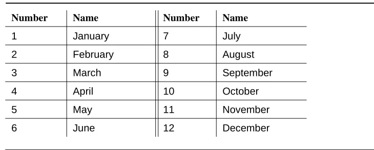
11. Type display time and press Enter to verify date and time data. Table 3. English Month Names
Number Name Number Name
1 January 7 July
2 February 8 August
3 March 9 September
4 April 10 October
5 May 11 November
Verify Software Version (si, r only)
For standard reliability:
1. Type list configuration software-version and press Enter to verify the system software version (in the Memory Resident field).
For high or critical reliability:
1. Type list configuration software-version long and press Enter to verify the system software version (in the Memory Resident field)
Verify Additional Administration
1. Perform a sanity check on the system by executing the following commands to ensure the translations were read in properly:
a. list station
b. list trunk-group
c. list hunt-group
This ensures there is no translation corruption and the translations can be saved with the new software.
2. Notify the switch administrator that for any previous login names and passwords that still exist, the passwords expire in 24 hours. When changed, the new login names and passwords must conform to the following requirements:
As before, a login name must have 3 to 6 alphanumeric characters. A password must have 4 to 11 characters, including at least 1 alphabetic character and 1 numeric character.
Set Core Dump Vector (r only)
1. Type set vector f spe-maint and press Enter to set the core dump vector to perform a core dump on any system restart.
Enable TTI
NOTE:
Do this step only if you disabled the TTI before the upgrade and you want it enabled.
Enable Scheduled Maintenance
1. Type change system-parameters maintenance and press Enter.
2. Type the appropriate time in the Start field to enable scheduled daily maintenance. Make sure the Save Translation field is set to daily.
Enable Customer Options and Alarm Origination
1. Get the DOSS order number of the upgrade from the project manager and ask the regional Customer Software Administration to complete the steps in the shaded box. See ‘‘Where to Call for Technical Support’’ on page 22 for telephone numbers.
NOTE:
As part of the system registration process, the INADS Database Administrator enables Alarm Origination.
2. When administration is completed, log in as craft.
"init" login administration:
1. Log in as init.
2. Type change system-parameters customer-options and press Enter to verify that the customer options are properly set.
3. Go to screen 6, QSIG Optional Features, and set the Basic Call Setup field to y if the customer was using Supplementary Services Protocol b or d on an ISDN-PRI trunk group before the upgrade.
4. Type change system-parameters offer-options and press Enter.
5. If the Activate Offer field is n, set it to y and press Tab. A warning message lets you know whether you need to save translations and reboot to make the change permanent.
6. Press Enter to effect the changes or Cancel if there were no changes.
Resolve Alarms
1. Type display alarms and press Enter to examine the alarm log. Resolve any alarms that may exist using
• DEFINITY Enterprise Communications Server Maintenance for R8csi.
• DEFINITY Enterprise Communications Server Maintenance for R8si.
• DEFINITY Enterprise Communications Server Maintenance for R8r.
Check Link Status
1. Type display communication-interface links and press Enter. Compare it with the earlier status.
2. Type status link number and press Enter. Repeat this step for each link.
3. For csi, check that DS1 trunks and BRI phones are functioning normally. Refer to DEFINITY Enterprise Communications Server Maintenance for R8csi to test or restore the out-of-service links.
Save Translations
1. For csi/si, type save translation and press Enter to copy upgraded translations in memory to the translation card, which takes about 10 minutes.
or
For r, type save translation and press Enter to copy upgraded translations in memory to the system disk, which takes about 2 minutes.
Restore Announcements (csi/si only)
1. Type restore announcements and press Enter to copy announcements from the translation card to memory, which takes about 40 minutes.
Save Announcements (r only)
Back Up Disk (r only)
1. Type backup disk and press Enter to back up all changed files to the removable media. This takes about 15 minutes.
2. Type test stored-data and press Enter to verify the consistency of the MSS files on the disk and removable media.
If standard reliability:
3. Type list configuration software-version and press Enter to verify all the files one last time.
If high or critical reliability:
1. Type list configuration software-version long and press Enter to verify all the files one last time.
Return Replaced Equipment
1. Return replaced equipment to Lucent Technologies according to the requirements outlined in:
BCS/Material Logistics, MSL/Attended Stocking Locations
Methods and Procedures for Basic Material Returns
2. Retain the old translation card for up to 10 business days to verify that the customer is satisfied and that there is no need to reverse the upgrade.
Where to Call for Technical Support
Refer to the table below for the telephone numbers for technical support.
Telephone Number
DEFINITY Helpline (feature administration and system applications) 1-800-225-7585 Lucent Technologies Toll Fraud Intervention 1-800-643-2353 Lucent Technologies National Customer Care Center 1-800-242-2121 Lucent Technologies Corporate Security 1-800-822-9009 Streamlined Implementation (for missing equipment) 1-800-772-5409 USA/Canada Technical Service Center 1-800-248-1234
ITAC 1-303-804-3777
Lucent Technologies Centers of Excellence
Asia/Pacific Regional Support Center 65-872-8686 Western Europe/Middle East/South Africa 44-1252-77-4800
Central/Eastern Europe 361-345-4334
Central/Latin America Caribbean 1-303-804-3778
Australia 61-2-9352-9090
IP Solutions
DEFINITY ECS IP Solutions allows you to send voice and fax from the DEFINITY ECS through an Internet protocol (IP) network to other DEFINITY ECSs having this feature or to other H.323 V2 compliant endpoints. It is implemented using the TN2302AP IP Media Processor and Release 8.3 or later software.
NOTE:
The “P” designation means the firmware on the circuit pack is programmable, a feature available beginning with Release 9.
IP trunking operating mode is still available using the TN802 IP Trunking (with Release 7) or the TN802B IP Interface Assembly (with Release 8.2), which offers both IP trunk and MedPro operating modes. Unlike the TN802B IP Interface Assembly, the TN2302AP operates in one mode: Media Processor (MedPro), which is H.323 V2 compatible. The TN2302AP works on all 3 DEFINITY ECS platforms (r, si, csi), beginning with R8.3, and DEFINITY ONE.
For information on TN802 IP Trunking, refer to the DEFINITY Enterprise
Communications Server Release 7 Installation and Test for Multicarrier Cabinets. For information on the TN802B IP Interface Assembly, refer to the DEFINITY Enterprise Communications Server Release 8 Installation and Test for Multicarrier Cabinets.
The following sections describe the process for
• Preparing for Installation and Upgrade
• Installing the TN2302AP IP Media Processor
• Upgrading TN802 IP Trunking to TN2302AP IP Media Processor
• Upgrading a TN802B IP Interface Assembly to TN2302AP IP Media Processor
For administration, refer to the DEFINITY Enterprise Communications Server Release 8 Administration for Network Connectivity.
Preparing for Installation and Upgrade
In addition to the TN2302AP IP Media Processor, you must also install and administer a C-LAN circuit pack (TN799B or later). For C-LAN administration, refer to DEFINITY Enterprise Communications Server Release 8 Administration for Network Connectivity.
Each TN2302AP can support between 32 and 64 voice channels, depending on the codecs used.
Check your onsite equipment
Have the following equipment on site before your shipment arrives:
• An unoccupied port slot in the DEFINITY ECS for each TN2302AP IP Media Processor
NOTE:
The TN2302AP consumes 16 W of power per slot compared with an average of 15 W per slot. Do not fill every available slot in a given carrier with them.
• An additional unoccupied port slot for the TN799B, if needed. If you have an existing C-LAN TN799 circuit pack, replace it with the TN799B or later if it is to be used for IP solutions registration.
• A 10 BaseT or 10/100 BaseT Ethernet connection into your local area network (LAN) for the TN2302AP.
• A 10 BaseT Ethernet connection into your LAN for the TN799B.
• Valid, unused IP addresses on your network (one for each TN2302AP or TN802/B and one for each C-LAN). You also need the subnet mask and default gateway.
NOTE:
The customer provides the IP address, subnet mask, and gateway address.
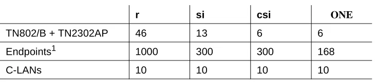
Table 4. Release 8.3 software limits
r si csi ONE
TN802/B + TN2302AP 46 13 6 6
Endpoints1 1000 300 300 168
C-LANs 10 10 10 10
1The administered IP endpoints may be a mix of any of these types: H.323 trunks, H.323
Check your shipment
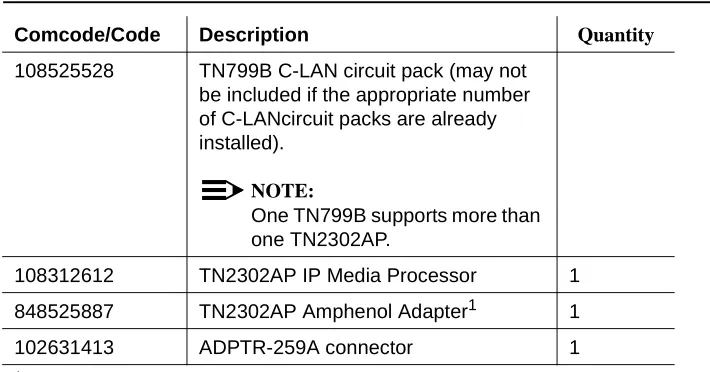
When your DEFINITY ECS IP Solutions order arrives at your site, check the contents (see Table 5).
1. Inspect the shipping carton for damage before opening it. If the box is damaged, do not open it. Inform the shipping company, and ask for instructions on filing a claim.
2. If the box is undamaged, check the contents against the packing slip. Check the condition of each component, and note any damage or
shortages on the packing slip. The carton should contain the items in Table 5 for each TN2302APIP Media Processor ordered.
3. Read and follow any directions inserted into the package by the factory.
NOTE:
The customer must provide one CAT5 or better cable for each TN2302AP. Table 5. Required Hardware
Comcode/Code Description Quantity
108525528 TN799B C-LAN circuit pack (may not be included if the appropriate number of C-LANcircuit packs are already installed).
NOTE:
One TN799B supports more than one TN2302AP.
108312612 TN2302AP IP Media Processor 1
848525887 TN2302AP Amphenol Adapter1 1
102631413 ADPTR-259A connector 1
1The adapter has an amphenol connector on one side and an RJ45 connector on
Figure 1. TN2302AP Amphenol Adapter
Installing the TN2302AP IP Media Processor
To install a TN2302AP IP Media Processor, you must install
• One or more TN2302AP circuit pack
• One or more TN799B or later circuit pack (A TN799B can support more than one TN2302AP)
• An IP Media Processor adapter.
Connect the cables for TN799B
1. Determine into which port slot(s) you are putting the TN799B C-LAN and circuit pack(s).
From the rear of the cabinet:
2. Connect a 259A connector to the backplane connector corresponding to each TN799B slot.
3. Connect one end of each DW8 cable to each 259A connector. Figure Notes
1. Amphenol connector to backplane connector corresponding to TN2302AP slot
2. To Ethernet
3. 9-pin connector for maintenance
addfipm2 KLC 0060700
10/100bTETHERNET RS232DEBUG
2
Connect the cables for TN2302AP
1. Determine into which port slots you are putting the TN2302AP IP Media Processor circuit packs.
From the rear of the cabinet:
2. Connect the amphenol connector on the adapter to the backplane connector corresponding to each TN2302AP slot.
NOTE:
Early orders may include a cable with the appropriate connectors rather than the adapter.
Connect the Ethernet
1. Connect the network cable(s) to the ETHERNET connector on the TN2302AP Amphenol adapter(s).
NOTE:
You need a CAT5 or better cable for 100-Mbps operation.
Install the Circuit Packs
!
CAUTION:
When adding or replacing any hardware, be sure to ground yourself against electrostatic discharge (ESD) by wearing a grounded wrist strap.
NOTE:
The TN799B and TN2302AP circuit packs are hot-swappable, so you do not need to power down the carrier to install them.
If replacing the existing TN799 circuit pack, remove it first and replace it with the new TN799B.
1. Insert the TN799B circuit pack into the port slot identified earlier.
NOTE:
To properly seat the circuit pack, push firmly on the front of the faceplate until the latch reaches the bottom rail of the carrier. Then close the latch until it is fully engaged.
3. Type list configuration all and press Enter to verify that the system recognizes the TN2302AP circuit packs.
Figure 2. TN2302AP IP Interface faceplate
Lucent
c
kdfpro1 KLC 060700
100bT
LINK
TRMT
Initial Administration Steps for C-LAN and
IP Media Processor
NOTE:
Refer to the DEFINITY Enterprise Communications Server Release 8 Administration for Network Connectivity for specific information.
1. Log in as craft.
2. Type change node-names and press Enter.
3. On page 2, type in the node names and IP addresses for the TN799B and the TN2302AP.
NOTE:
The customer or design team provides the actual name and address. Suggest a generic name and not one tied to the circuit pack.
4. Type display circuit-pack and press Enter. Verify that the TN2302AP shows up in the Code column.
5. Type change ip-interfaces and press Enter.
change node-names Page 2 of 6 NODE NAMES
Name IP Address Name IP Address
clan-a1 192.168.1 .31 . . .
clan-b1 192.168.2 .31 . . .
default 0 .0 .0 .0 . . .
mrmedpro1 192.168.1 .81 . . .
. . . . . .
. . . . . .
.
NOTE:
The TN802B and the TN2302AP both display as Type MEDPRO on the IP Interfaces screen.
NOTE:
The customer provides the IP address, subnet mask, and gateway address.
6. Type in the following information for the TN2302AP IP Media Processor and TN799B C-LAN:
— Set Slot field to UUCSS.
— The Code and SFX fields are automatically populated with TN799B and TN2302AP.
— In the Node Name field type the same node name entered on the Node Name screen.
— In the Subnet Mask field use the default setting unless you are given a different subnet mask.
— In the Gateway Address field use the address you are given or leave blank.
— Set the Net Region field to 1 unless you are given a different number. More information about Network Regions can be found in Administration for Network Connectivity, 555-233-504.
— Set the Enable Eth Pt field to y
change ip-interfaces Page 1 of 2 IP INTERFACES
Inter-region IP connectivity allowed? n
Enable Net Eth Pt Type Slot Code Sfx Node Name Subnet Mask Gateway Address Rgn y C-LAN 01A09 TN799 B clan-a1 255.255.255.0 . . . 1 y MEDPRO 01A13 TN802 B med-a1 255.255.255.0 192.168.10 .21 1 y C-LAN 01B03 ppp10 255.255.255.0 . . . 1
y MEDPRO 01B09 TN2302 AP mrmedpro1 255.255.255.0 . . . 1
n 255.255.255.0 . . . n 255.255.255.0 . . . n 255.255.255.0 . . . n 255.255.255.0 . . . n 255.255.255.0 . . . n 255.255.255.0 . . . n 255.255.255.0 . . . n 255.255.255.0 . . . n 255.255.255.0 . . . n 255.255.255.0 . . .
n 255.255.255.0 . . .
n 255.255.255.0 . . .
Refer to the DEFINITY Enterprise Communications Server Release 8 Administration for Network Connectivity for more information on these administration steps and for the steps to administer IP Softphones and H.323 trunks.
NOTE:
Administration of the TN2302AP is the same as that for the TN802B.
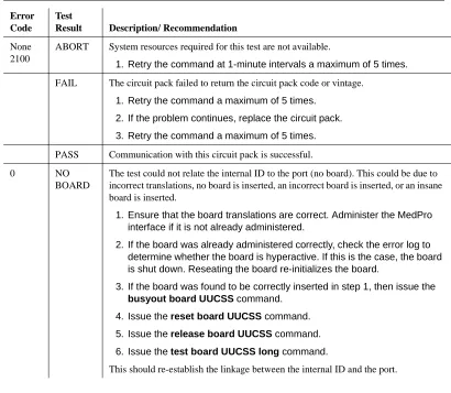
Test the External Connection to the LAN
To test the external IP connections, ping the C-LAN or IP Media Processor server and ping a known computer connected to your network. If everything is configured correctly, the Result column on the Ping Results screen reads pass. If it reads abort, verify the IP-address information and check the connectivity, including the cabling.
1. Type ping ip-address nnn.nnn.nnn.nnn board UUCSS and press Enter. The variable nnn.nnn.nnn.nnn is the IP address of the TN2302AP IP Media Processor and UUCSS is the cabinet, carrier, and slot of the TN2302AP IP Media Processor.
2. Type ping ip-address nnn.nnn.nnn.nnn board UUCSS and press Enter. The variable nnn.nnn.nnn.nnn is the IP address of the customer’s gateway and UUCSS is the cabinet, carrier, and slot of the TN2302AP IP Media Processor.
3. Type ping ip-address nnn.nnn.nnn.nnn board UUCSS and press Enter. The variable nnn.nnn.nnn.nnn is the IP address of another computer beyond the gateway and UUCSS is the cabinet, carrier, and slot of the TN2302AP IP Media Processor.
The TN2302AP IP Media Processor is now installed in the DEFINITY carrier and connected to the IP network.
ping ip-address 192.168.10.21 PING RESULTS
End-pt IP Port Port Type Result Time(ms) Error Code
Upgrading TN802 IP Trunking to TN2302AP IP
Media Processor
To upgrade IP Trunking to IP Media Processor, you must replace
• The TN802 circuit pack with a TN2302AP circuit pack • The TN799 circuit pack with a TN799B circuit pack
• The H600 512, G1 external cable assembly with an IP Media Processor adapter.
Pre-upgrade steps
1. Type list configuration all and press Enter to locate all the TN802 circuit pack ports.
2. Type display port UUCSSppp and press Enter to find the trunk group number associated with the TN802 circuit pack port.
3. Type change trunk-group number and press Enter. Go to screen 4. Delete all the TN802 ports.
4. Repeat steps 1 through 3 for each port.
5. Type remove ds1 UUCSS and press Enter.
Remove the Circuit Packs
!
CAUTION:
When adding or replacing any hardware, be sure to ground yourself against electrostatic discharge (ESD) by wearing a grounded wrist strap.
NOTE:
The TN799B and TN2302AP circuit packs are hot-swappable, so you do not need to power down the carrier to remove or install them.
1. Press the recessed Reset button on the TN802 circuit pack until MSHUT* starts flashing on the LCD. When MSHUT* is in a steady state, it is safe to remove the circuit pack.
Replace the Cables
1. Disconnect the network cable from the Ethernet connection.
2. Turn off the monitor and unplug it from the AC outlet, if necessary.
3. Disconnect the monitor, keyboard, and mouse from the H600-512 external cable assembly, if necessary.
4. Turn off the modem and unplug it from the AC outlet.
5. Disconnect the modem’s RS232 port from the H600-512 external cable assembly.
From the rear of the cabinet:
NOTE:
Early models may use a cable with the appropriate connectors rather than the adapter.
6. Disconnect the amphenol connector on the existing external cable
assembly from the backplane connector corresponding to the TN802 circuit pack.
7. Connect the amphenol connector of the TN2302AP Amphenol adapter to the backplane connector corresponding to the slot selected for the TN2302AP circuit pack.
NOTE:
The TN802 occupied 3 slots, and the cable was connected to the rightmost backplane slot. For convenience use the same rightmost slot vacated by the TN802 circuit pack for the TN2302APcircuit pack.
8. Connect the network cable to the Ethernet connector on the TN2302AP Amphenol adapter.
Install the circuit packs
1. If replacing the TN799 circuit pack, install the TN799B circuit pack in the slot vacated by the TN799 circuit pack.
2. For convenience install the TN2302AP circuit pack in the rightmost slot vacated by the TN802. The other 2 slots are now available for other circuit packs.
When you plug in the TN2302AP IP Media Processor, the circuit pack starts to boot. The RED LED stays on until an IP address is assigned to the circuit pack.
Administration Steps
1. Administer the TN799B C-LAN. Refer to the DEFINITY Enterprise Communications Server Release 8 Administration for Network Connectivity.
2. Administer the IP Media Processor, which is usually done remotely. Call your service representative to start the process.
3. Complete the administration and testing. Refer to ‘‘Initial Administration Steps for C-LAN and IP Media Processor’’ on page 29 and ‘‘Test the External Connection to the LAN’’ on page 31.
Upgrading a TN802B IP Interface Assembly to
TN2302AP IP Media Processor
To upgrade IP Interface Assembly to IP Media Processor, you must replace
• The TN802B circuit pack with a TN2302AP circuit pack
• The TN799 circuit pack with a TN799B circuit pack, if necessary
• The H600 512, G1 external cable assembly with an IP Media Processor adapter.
Pre-upgrade steps
1. Type change ip-interfaces and press Enter.
.
change ip-interfaces Page 1 of 2 IP INTERFACES
Inter-region IP connectivity allowed? n
Enable Net Eth Pt Type Slot Code Sfx Node Name Subnet Mask Gateway Address Rgn
y C-LAN 01A09 TN799 B clan-a1 255.255.255.0 . . . 1
n MEDPRO med-a1 255.255.255.0 192.168.10 .21 1
n 255.255.255.0 . . .
n 255.255.255.0 . . .
n 255.255.255.0 . . . n 255.255.255.0 . . . n 255.255.255.0 . . . n 255.255.255.0 . . . n 255.255.255.0 . . . n 255.255.255.0 . . . n 255.255.255.0 . . . n 255.255.255.0 . . . n 255.255.255.0 . . . n 255.255.255.0 . . . n 255.255.255.0 . . .
n 255.255.255.0 . . .
2. Set the Enable Eth Pt field to n 3. Press Enter to effect the change.
4. Type change ip-interfaces and press Enter.
5. Delete the information in the Type, Slot, and Node Name fields for each TN802B you are replacing.
6. Press Enter to save the information and effect the new settings.
Remove the Circuit Packs
!
CAUTION:
When adding or replacing any hardware, be sure to ground yourself against electrostatic discharge (ESD) by wearing a grounded wrist strap.
NOTE:
The TN799B and TN2302AP circuit packs are hot-swappable, so you do not need to power down the carrier to remove or install them.
NOTE:
If replacing the existing TN799 circuit pack, remove it first and replace it with the new TN799B.
1. Press the recessed Reset button on the TN802B circuit pack until MSHUT* starts flashing on the LCD. When MSHUT* is in a steady state, it is safe to remove the circuit pack.
2. Remove the TN799 and TN802B circuit packs.
Replace the Cables
1. Disconnect the network cable from the Ethernet connection.
2. Turn off the modem and unplug it from the AC outlet. It is not needed for the TN2302AP.
From the rear of the cabinet:
4. Disconnect the amphenol connector on the external cable assembly from the backplane connector corresponding to the TN802B circuit pack.
5. Connect the amphenol connector on the TN2302AP Amphenol adapter to the backplane connector corresponding to slot selected for the TN2302AP circuit pack.
NOTE:
The TN802 circuit pack occupied 3 slots, and the cable was connected to the rightmost slot. For convenience use the same rightmost slot vacated by the TN802 circuit pack for the TN2302AP circuit pack. The other 2 slots are now available for other circuit packs.
6. Connect the network cable to the Ethernet connector on the TN2302AP Amphenol adapter.
Install the circuit packs
1. If replacing the TN799 circuit pack, install the TN799B circuit pack in the slot vacated by the TN799 circuit pack.
2. For convenience install the TN2302AP circuit pack in the rightmost slot vacated by the TN802 circuit pack. The other 2 slots are now available for other circuit packs.
When you plug in the TN2302AP IP Media Processor, the circuit pack starts to boot. The RED LED stays on until an IP address is assigned to the circuit pack.
3. Type list configuration all and press Enter to verify that the system recognizes the TN2302AP circuit packs.
Administration Steps
1. Administer the TN799B C-LAN, if necessary. Refer to the DEFINITY Enterprise Communications Server Release 8 Administration for Network Connectivity, 555-233-504.
2. Administer the IP Media Processor, which is usually done remotely. Call your service representative to start the process.
Modified Maintenance Objects
These are the modified Maintenance Objects for R8.3 and the Maintenance Documents where they can be found.
ISDN-SGR (ISDN-PRI Signaling Group)
Document number 555-233-221.ISDN-TRK (DS1 ISDN Trunk)
Document number 555-233-752.
MO Name (in
Alarm Log) Alarm Level
Initial Command to Runa
a. grp# is the signaling group number (1-166); the test sequence can be either short or long.
Full Name of MO
ISDN-SGR MINOR test sig-group grp# ISDN-PRI Signaling Group
ISDN-SGR WARNING test sig-group grp# ISDN-PRI Signaling Group
MO Name (in
Alarm Log) Alarm Level Initial Command to Runa
a. UU is the universal cabinet number (1 for PPN, 2 -44 for EPN s). C is the carrier designation (A, B, C, D, or E). SS is the number of the slot in which the circuit pack resides (01 to 21). pp is the two digit port number (01, 02, ...).
Full Name of MO
ISDN-TRKb
b. For additional repair information, see also DS1-BD for TN767 ports and UDS1-BD for TN464C/D ports.
MAJORc
c. A MAJOR alarm on a trunk indicates that alarms on these trunks are not downgraded by the set options command.
test port UUCSSpp l DS1 ISDN Trunk
ISDN-TRK MINOR test port UUCSSpp l DS1 ISDN Trunk
TIE-DS1 (DS1 Tie Trunk)
Document number 555-233-752.
MO Name (in
Alarm Log) Alarm Level Initial Command to Run Full Name of MO
TIE-DS1a
a. For additional repair information, see DS1-BD documentation if the tie trunk is on a TN722 or TN767 DS1 circuit pack. See UDS1-BD documentation if the tie trunk is on a TN464C/D UDS1 circuit pack.
MAJORb
b. A MAJOR alarm on a trunk indicates that alarms on these trunks are not downgraded by the set
options command and that at least 75% of the trunks in this trunk group are alarmed. test trunk grp/mbr lc
c. For TN767B vintage 8 or 9 circuit packs, a failure of Test #136 causes a subsequent failure of Test #7. Test #136 is part of the short sequence and generates off-board alarms Test #7 is part of the long sequence and generates on-board alarms. Before entering busyout, release, reset or test board long commands, check the vintage number of the circuit pack with list
configuration board UUCSS. If it is TN767B vintage 8 or 9, do not use the above commands
until first making sure that Test #136 passes via test board short. Otherwise, extraneous on-board alarms may be generated.
DS1 Tie Trunk
TIE-DS1 MINOR test trunk grp/mbr ld
d. For TN767B vintage 8 or 9 circuit packs, a failure of Test #136 causes a subsequent failure of Test #7. Test #136 is part of the short sequence and generates off-board alarms Test #7 is part of the long sequence and generates on-board alarms. Before entering busyout, release, reset or test board long commands, check the vintage number of the circuit pack with list
configuration board UUCSS. If it is TN767B vintage 8 or 9, do not use the above commands
until first making sure that Test #136 passes via test board short. Otherwise, extraneous on-board alarms may be generated.
DS1 Tie Trunk
New Maintenance Objects
The following sections contain the new Maintenance Objects for R8.3.
IPMEDPRO (IP Media Processor Circuit
Pack)
The TN2302 (IPMEDPRO) circuit pack is the next generation H.323 platform. The TN2302 includes a 10/100 BaseT Ethernet interface to support H.323 endpoints for DEFINITY IP (Internet Protocol) trunks and H.323 endpoints. The TN2302 can perform echo cancellation, silence suppression, DTMF detection, and
conferencing. It supports the following codecs, fax detection for them, and conversion between them:
• G.711 (mu-law or a-law, 64Kbps); • G.723.1 (6.3Kbps or 5.3Kbps audio); • G.729A (8Kbps audio);
The TN2302 IPMEDPRO circuit board is used by the DOLAN (Definity on the LAN) feature to provide voice over IP connectivity. The TN2302 can run the Media Processor (MedPro) application, which allows the TN2302 to act as a service circuit to terminate generic RTP streams used to carry packetized audio over an IP network. As part of the overall H.323 implementation, the TN2302 circuit pack handles the audio streams while the TN799 C-LAN handles the TCP/IP signaling channels. This maintenance object applies only to a TN2302 IPMEDPRO running the Media Processor application.
The Media Processor application is built upon the existing ITS software, and as
MO Name (in Alarm Log)
Alarm
Level Initial Command to Runa
a. UU is the universal cabinet number (1 for PPN, 2 - 44 for EPNs). C is the carrier designation (A, B, C, D, or E). SS is the number of the slot in which the circuit pack resides (01 to 21).
Full Name of MO
IPMEDPRO MAJOR test board UUCSS sh IP Media Processor Circuit Pack
IPMEDPRO MINOR test board UUCSS l IP Media Processor Circuit Pack
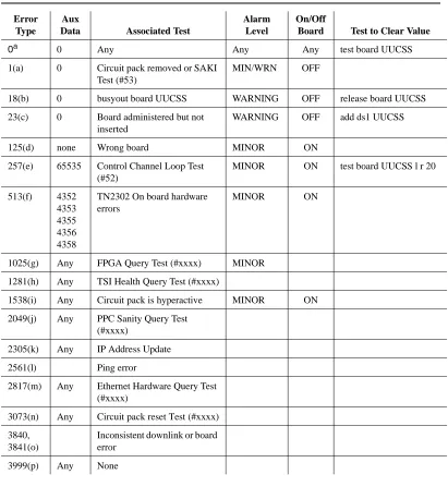
Error Log Entries and Test to Clear Values
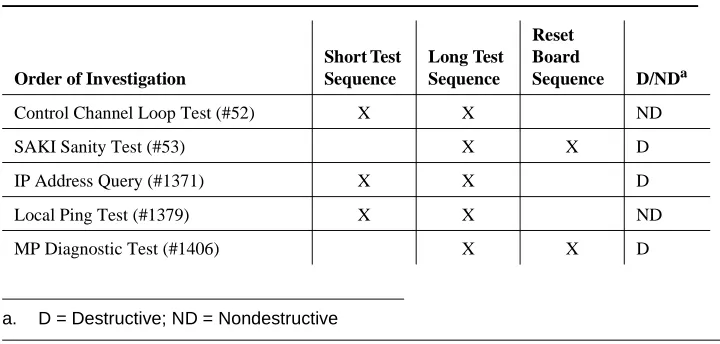
a) Run the Short Test Sequence first. If all tests pass, run the Long Test Sequence. Refer to the appropriate test description and follow the recommended procedures.
Table 6. DS1 Interface Circuit Pack Maintenance Error Log Entries
Error Type
Aux
Data Associated Test
Alarm Level
On/Off
Board Test to Clear Value
0a 0 Any Any Any test board UUCSS
1(a) 0 Circuit pack removed or SAKI Test (#53)
MIN/WRN OFF
18(b) 0 busyout board UUCSS WARNING OFF release board UUCSS
23(c) 0 Board administered but not inserted
WARNING OFF add ds1 UUCSS
125(d) none Wrong board MINOR ON
257(e) 65535 Control Channel Loop Test (#52)
MINOR ON test board UUCSS l r 20
513(f) 4352 4353 4355 4356 4358
TN2302 On board hardware errors
MINOR ON
1025(g) Any FPGA Query Test (#xxxx) MINOR
1281(h) Any TSI Health Query Test (#xxxx)
1538(i) Any Circuit pack is hyperactive MINOR ON
2049(j) Any PPC Sanity Query Test (#xxxx)
2305(k) Any IP Address Update
2561(l) Ping error
2817(m) Any Ethernet Hardware Query Test (#xxxx)
3073(n) Any Circuit pack reset Test (#xxxx)
3840, 3841(o)
Inconsistent downlink or board error
Notes:
a. Error Type 1 -This error indicates that the circuit pack has been removed from the system or is not fully administered. The alarm is logged about 15 minutes after the circuit pack has been removed, or 11-minutes after the
SAKI Test (#53) fails.
To be fully administered, a IPMEDPRO circuit pack must meet all of these 4 conditions:
1. Have an entry in the circuit pack form (change circuit pack)
2. Have the MedPro ip address administered (change node-names)
3. Be enabled (change ip-interface)
4. Be physically inserted into the correct slot
If the circuit pack has an entry in the circuit pack form and either of the other two conditions are not met, a MINOR alarm is logged. To resolve the error:
1. Make sure all conditions for administration are met and that a functioning MedPro circuit pack is inserted in the correct slot
OR
2. Completely remove the IPMEDPRO from the system using the following steps:
a. Remove the administered IP-Interface associated with the circuit pack.
b. Physically remove the circuit pack from the slot.
c. Execute the remove medpro UUCSS and change circuit pack UUCSS commands.
b. Error Type 18 -The IPMEDPRO Interface circuit pack has been busied out by a busyout board UUCSS command.
1. Release the circuit pack (release board UUCSS).
c. Error Type 23 -The IPMEDPRO circuit pack is not completely
administered. To be fully administered, a IPMEDPRO circuit pack must meet all of these 4 conditions:
1. Have an entry in the circuit plan (change circuit pack)
2. Have the IPMEDPRO IP address administered (change node-names)
3. Be enabled (change ip-interface)
d. Error Type 125 - No Aux Data: The wrong circuit pack is inserted in the slot where this circuit pack is logically administered.
1. Remove the wrong circuit pack and insert the logically administered circuit pack
OR
2. Re-administer this slot to match the circuit pack inserted (change circuit-pack).
e. Error Type 257 - This error is associated with a failure of the Control Channel Test #52. Refer to Control Channel Test #52 Maintenance documentation for details.
f. Error Type 513 - This error indicates different hardware device problems on the board. They include an external RAM failure, and internal RAM failure, a ROM checksum failure, message corruption, and a program logic inconsistency. The counter can be alarmed if it goes over threshold. There are really no good associated tests for these inline errors, if they continue to happen, an alarm will occur, otherwise the counter will be decremented via the leaky bucket.
g. Error Type 1025 - FPGA failure. This failure indicates a problem on the FPGA device located on the TN2302. The last byte of the inline error gives a hint as to the problem with the FPGA. The diagnostic strategy for this inline error is to take the switch resources associated with all of the DSPs out of service, and then to reset the FPGA. The reset of the FPGA will cause an uplink response as to whether the reset passed or not. There are several error conditions that can be sent up in the error message for the FPGA, they will all be treated as the same failure by switch software.
h. Error Type 1281 - TSI failures. There are potentially 2 different TSI failures that can occur, one is a TSI DSP failure and the other is a TSI FPGA failure. Both of these failures will be looked for by switch software, but, they will both cause the same response by software. The diagnostic strategy for this inline error is to take the switch resources associated with all of the DSPs out of service, and then to reset the TSI (the reset downlink is slightly different depending on whether the TSI DSP or the TS