585-313-204 108647280 January 2000 Issue 2
Version 7.0
Copyright Copyright © 2000 by Lucent Technologies. All rights reserved.
Printed in the USA.
This material is protected by the copyright laws of the United States and other countries. It may not be reproduced, distributed, or altered in any fashion by any entity (either internal or external to Lucent Technologies), except in accordance with applicable agreements, contracts or licensing, without the express written consent of the Business Communications Systems (BCS) Global Learning Solutions (GLS) organization and the business management owner of the material.
Acknowledgment This document was prepared by the GLS organization of the BCS division of Lucent Technologies. Offices are located in Denver CO, Columbus OH, Middletown NJ, and Basking Ridge NJ, USA.
Trademarks Lucent Technologies has made every effort to supply the following trademark information about company names, products, and services mentioned in the Intuity CONVERSANT documentation library:
• Adobe Systems, Inc. — Trademarks: Adobe, Acrobat.
• CLEO Communications — Trademarks: LINKix.
• Hayes Microcomputer Products, Inc. — Trademarks: Hayes, Smartmodem.
• Intel Corporation — Registered trademarks: Pentium.
• Interface Systems, Inc. — Trademarks: CLEO.
• International Business Machines Corporation — Registered trademarks: IBM, VTAM.
• Lucent Technologies — Registered trademarks: 5ESS, AUDIX,
CONVERSANT, DEFINITY, Voice Power. Trademarks: FlexWord, Intuity, Lucent.
• Microsoft Corporation — Registered trademarks: Excel, Internet Explorer, Microsoft, MS, MS-DOS, Windows, Windows NT.
• Minnesota Mining and Manufacturing — Trademarks: 3M.
• Netscape Communications — Trademarks: Netscape Navigator.
• Novell, Inc. — Registered trademarks: Novell.
• Oracle Corporation — Trademarks: OBJECT*SQL, ORACLE, ORACLE*Terminal, PRO*C, SQL*FORMS, SQL*Menu, SQL*Net, SQL*Plus, SQL*ReportWriter.
• Phillips Screw Co. — Registered trademarks: Phillips.
• UNIX System Laboratories, Inc. — Registered trademarks: UNIX.
• Veritas Software Corporation — Trademarks: VERITAS.
• Xerox Corporation — Trademarks: Ethernet.
Limited Warranty Lucent Technologies provides a limited warranty on this product. Refer to the “Limited Use Software License Agreement” card provided with your package. Lucent Technologies has determined that use of this electronic data delivery system cannot cause harm to an end user's computing system and will not assume any responsibility for problems that may arise with a user's computer system while accessing the data in these document.
Every effort has been made to make sure that this document is complete and accurate at the time of release, but information is subject to change.
United States FCC Compliance Information
Part 15: Class A statement. This equipment has been tested and found to comply with the limits for a Class A digital device, pursuant to Part 15 of the FCC Rules. These limits are designed to provide reasonable protection against harmful interference when the equipment is operated in a commercial environment. This equipment generates, uses, and can radiate
radio-frequency energy and, if not installed and used in accordance with the instructions, may cause harmful interference to radio communications. Operation of this equipment in a residential area is likely to cause harmful interference, in which case the user will be required to correct the
Canadian Department of Communications (DOC) Interference Information
This digital apparatus does not exceed the Class A limits for radio noise emissions set out in the radio interference regulations of the Canadian Department of Communications.
Le Présent Appareil Nomérique n’émet pas de bruits radioélectriques dépassant les limites applicables aux appareils numériques de la class A préscrites dans le reglement sur le brouillage radioélectrique édicté par le ministére des Communications du Canada.
European Union Declaration of Conformity
Lucent Technologies Business Communications Systems declares that the Intuity™ CONVERSANT® System equipment specified in this document conforms to the referenced European Union (EU) Directives and Harmonized Standards listed below: EMC Directive 89/336/EEC Low-Voltage Directive 73/23/EEC. The “CE” mark affixed to the equipment means that it conforms to the above directives.
Telecom New Zealand Ltd Warning Notices
IMPORTANT NOTICE: Under power failure conditions, this device may not operate. Please ensure that a separate telephone, not dependent on local power, is available for emergency use.
AUTOMATIC RE-ATTEMPTS TO THE SAME NUMBER: Some parameters required for compliance with Telecom’s Telepermit requirements are dependent on the equipment (PC) associated with this device. The associated equipment shall be set to operate within the following limits for compliance with Telecom specifications:
• There shall be no more than 10 call attempts to the same number within any 30 minute period for any single manual call initiation, and,
• The equipment shall go on-hook for a period of not less than 30 seconds between the end of one attempts and the beginning of the next attempt. AUTOMATIC CALLS TO DIFFERENT NUMBERS: Some parameters required for compliance with Telecom’s Telepermit requirements are dependent on the equipment (PC) associated with this device. In order to operate within the limits for compliance with Telecom specifications, the associated equipment shall be set to ensure that automatic calls to different numbers are spaced such that there is not less than 5 seconds between the end of one call attempt and the beginning of the next attempt.
CALL ANSWERING (AUTOMATIC ANSWERING EQUIPMENT): Some parameters required for compliance with Telecom’s Telepermit requirements are dependent on the equipment (PC) associated with this device. In order to operate within the limits for compliance with Telecom specifications, the associated equipment shall be set to ensure that calls are answered between 3 and 30 seconds of receipt of ringing.
Toll Fraud Toll fraud is the unauthorized use of your telecommunications system by an unauthorized party, for example, persons other than your company’s employees, agents, subcontractors, or persons working on your company’s behalf. Note that there may be a risk of toll fraud associated with your telecommunications system and, if toll fraud occurs, it can result in substantial additional charges for your telecommunications services.
Your Responsibility for Your System’s Security
You and your system manager are responsible for the security of your system and for preventing unauthorized use. You are also responsible for reading all installation, instruction, and system administration documents provided with this product in order to fully understand the features that can introduce risk of toll fraud and the steps that can be taken to reduce that risk. Lucent
Lucent Technologies Fraud Intervention and Corporate Security
If you suspect that you are being victimized by toll fraud and you need technical support or assistance, call the Lucent Technologies National Customer Care Center Toll Fraud Intervention Hotline at 1 800 643-2353. Aside from whether immediate support is required, all toll fraud incidents involving Lucent products or services should be reported to Lucent Corporate Security at 1 800 821-8235. In addition to recording the incident, Lucent Corporate Security is available for consultation on security issues,
investigation support, referral to law enforcement agencies, and educational programs.
Documentation Ordering Information
To order a document, contact the Lucent Technologies Publications Center and specify the 9-digit document number, the issue number, and the issue date.
Write, Call, or Fax
Lucent Technologies Publications Center 2855 N. Franklin Road
Indianapolis, IN 46219
World Wide Web
Use a web browser to reach one of the following sites. Click Documents and follow the instructions at the site.
• Organizations within Lucent Technologies http://www.cic.lucent.com
• Lucent Technologies customers and others http://www.lucentdocs.com
Standing Orders
Copyright and Legal Notices
ii
Copyright. . . .ii
Acknowledgment. . . .ii
Trademarks . . . .ii
Limited Warranty . . . iv
United States FCC Compliance Information . . . iv
Canadian Department of Communications (DOC) Interference Information. . . v
European Union Declaration of Conformity. . . v
Telecom New Zealand Ltd Warning Notices . . . v
Toll Fraud . . . .vii
Documentation Ordering Information . . . viii
About This Book
xxii
Overview . . . xxiiIntended Audience . . . xxii
How To Use This Book. . . xxiii
For an Overview . . . xxiii
For Information on Hardware . . . xxiii
For Information on Features and Feature Packages . . . xxiv
To Locate Specific Topics . . . xxiv
Conventions Used in This Book . . . xxiv
Cross References and Hypertext . . . xxiv
Safety and Security Alert Labels . . . xxv
Getting Help . . . xxvi
Technical Assistance. . . . xxvii
Web Site . . . xxvii
Contact Numbers . . . xxvii
Related Resources. . . xxviii
Training . . . xxviii
Documentation . . . xxix
Using the CD-ROM Documentation . . . xxx
Setting the Default Magnification . . . .xxx
Adjusting the Window Size . . . xxxi
Hiding and Displaying Bookmarks . . . xxxi
Using the Button Bar . . . xxxi
Using Hypertext Links . . . xxxi
Navigating with Double Arrow Keys . . . xxxi
Searching for Topics . . . xxxi
Displaying Figures. . . xxxii
Printing the Documentation. . . xxxii
Comment Form . . . xxxiii
Contact Us Directly . . . xxxiv
1 Introduction
1
Overview . . . 1Voice Response Basics . . . 2
What the Intuity CONVERSANT System Does. . . 2
A Sample Transaction . . . 3
Nonautomated Transaction . . . 3
Types of Interactions Between Caller and Operator . . . 5
Automated Transaction Using the System . . . 6
Types of Interactions Between Caller and System . . . 7
System Hardware . . . 8
System Software . . . 9
System Features . . . . 10
Feature Packages . . . . 10
2 Hardware
11
Overview . . . . 11Standard System Hardware by Platform. . . . 12
MAP/100C . . . . 13
Standard System Hardware . . . 13
Standard Circuit Cards . . . 14
Standard Bus Cables . . . 16
Peripheral Devices . . . 17
Power Supply . . . 18
Views of the MAP/100C . . . 18
MAP/100P . . . . 22
Standard System Hardware . . . 22
Backplane . . . 23
Standard Circuit Cards . . . 24
Standard Bus Cables . . . 25
Peripheral Devices . . . 26
Power Supply . . . 28
Views of the MAP/100P . . . 28
MAP/40P . . . . 34
Standard System Hardware . . . 34
Backplane . . . 34
Standard Circuit Cards . . . 35
Standard Bus Cables . . . 36
Peripheral Devices . . . 37
Power Supply . . . 39
Views of the MAP/40P . . . 39
MAP/5P . . . . 42
Standard System Hardware . . . 42
Motherboard . . . 43
Standard Circuit Cards . . . 43
Standard Bus Cables . . . 44
Peripheral Devices . . . 45
Power Supply . . . 46
Views of the MAP/5P . . . 46
Optional System Hardware . . . . 49
Optional Circuit Cards . . . 49
Analog Circuit Cards . . . 50
Tip/Ring Circuit Cards . . . 50
Digital Circuit Cards . . . 52
E1/T1 (AYC21) Circuit Card . . . 53
Speech and Signal Processor Circuit Cards . . . 54
Data Communications Circuit Cards . . . 57
Synchronous Circuit Card . . . 57
Asynchronous 8-Port Circuit Cards. . . 58
Token Ring Circuit Card . . . 58
Ethernet LAN Circuit Card. . . 59
Other Optional Circuit Cards . . . 59
External Alarms Interface Circuit Card . . . 60
RAID Controller Circuit Card . . . 60
Optional Peripheral Equipment . . . . 60
Monitor . . . 61
Terminal Emulation . . . 62
Serial Mouse . . . 62
Printer . . . 62
Modem . . . 63
Resource Assignments, Limitations, and Maximums . . . . 65
Hardware Resource Allocator . . . 65
What the Hardware Resource Allocator Does . . . 65
Configuration Data Diskette . . . 67
Configuration Data Files . . . 68
Resource Assignments for Hardware Components. . . 69
Guidelines for the Addition of SCSI Devices . . . 73
Addition of SCSI Devices to the MAP/100C . . . 73
Addition of SCSI Devices to the MAP/100P . . . 74
Addition of SCSI Devices to the MAP/40P . . . 74
Addition of SCSI Devices to the MAP/5P . . . 74
Circuit Card Maximums . . . 75
3 Software
77
Overview . . . . 77UnixWare 2.1.2 Operating System. . . . 78
V7.0 System Base Software . . . . 80
V7.0 System Optional Software . . . . 82
Open Interface . . . . 95
SCSI . . . 95
UnixWare . . . 96
IRAPI. . . 97
ORACLE . . . 97
HLLAPI . . . 97
User Interfaces. . . . 98
Graphical User Interface . . . 98
UnixWare . . . 99
Graphical Speech Editor and FlexWord Toolkit. . . 99
Voice@Work . . . 99
Command Line . . . 100
Screens . . . 100
Application Development Tools . . . 100
Voice@Work . . . 101
Script Builder. . . 101
TAS Script . . . 102
Intuity Response API. . . 102
Voice Response Functions. . . 103
Announce . . . 104
Answer . . . 104
Background . . . 104
Call Transfers . . . 105
Disconnect . . . 109
Originate . . . 110
Converse Vector Step . . . 110
System Status and Monitoring . . . 111
Diagnostics . . . .111
System Monitor . . . 112
Trace . . . 112
Local System Status and Alerting . . . 112
Remote Maintenance Circuit Card . . . 113
Reports . . . 113
Speech . . . 114
Speech Development . . . 114
Coding and Storage . . . 115
Speech Play and Coding Capacities. . . 116
Speech Storage Capacities. . . 117
Speech Administration Capacities . . . 118
Communications . . . 119
Analog Telephony Interface. . . 120
Digital Telephony Interface . . . 121
Data Network . . . 122
Database Environment. . . 122
ORACLE Relational Database Management System 7.3.2 . . . 123
Database Capacities . . . 123
Hardware RAID . . . 126
5 Feature Packages
127
Overview . . . 127Adjunct/Switch Application Interface . . . 129
Software and Hardware Requirements . . . 132
Asynchronous Host Interface Toolkit. . . 134
Software and Hardware Requirements . . . 135
Call Center Application Solutions . . . 137
Customer Assist Solutions . . . 137
Agent Assist Solutions . . . 140
Optional Feature Package Enhancements . . . 141
Software and Hardware Requirements . . . 144
Call Classification Analysis . . . 149
Full CCA . . . 150
Software and Hardware Requirements . . . 151
SSP Channel Capacities for CCA . . . 151
Country-Specific Analog Switch Integration Packages . . . 152
Software and Hardware Requirements . . . 152
Dial Pulse Recognition . . . 153
Software and Hardware Requirements . . . 155
Software Requirements. . . 157
Enhanced File Transfer . . . 158
Software and Hardware Requirements . . . 158
External Alarms . . . 160
Software and Hardware Requirements . . . 160
FlexWord Toolkit . . . 162
Software and Hardware Requirements . . . 163
Form Filler Plus . . . 163
Software and Hardware Requirements . . . 164
Graphical Speech Editor . . . 166
Software and Hardware Requirements . . . 166
Line Side E1-DEFINITY . . . 167
Software and Hardware Requirements . . . 168
Platform Maximums . . . 169
Line Side T1-DEFINITY . . . 169
Software and Hardware Requirements . . . 170
Local Area Network Connectivity . . . 171
Software and Hardware Requirements . . . 172
Multi-Port Asynchronous Communications Interface . . . 172
Software and Hardware Requirements . . . 173
NetView Alarm Interface . . . 174
Primary Rate Interface . . . 176
Software and Hardware Requirements . . . 178
Script Builder. . . 180
Software and Hardware Requirements . . . 181
Script Builder FAX Actions . . . 186
Software and Hardware Requirements . . . 187
Some Uses for Script Builder FAX Actions in Applications . . . 188
FAX_Zapper . . . 192
Speech Recognition . . . 193
WholeWord Speech Recognition . . . 194
FlexWord Speech Recognition . . . 196
Synchronous Host Interface . . . 199
T1 E&M Protocol . . . 204
Software and Hardware Requirements . . . 204
Text-to-Speech . . . 205
Voice@Work . . . 208
Hardware and Software Requirements . . . 210
Hardware Requirements for PC . . . 210
Software Requirements. . . 211
Optional Equipment. . . 211
6 Requirements and Specifications
217
Overview . . . 217
Platform Specifications. . . 218
Power Requirements. . . 218
Space Requirements. . . 221
Environmental Considerations . . . 223
Telephone Network Characteristics . . . 224
Tip/Ring Telephony Interface Specifications . . . 225
Digital Telephony Interface Specifications. . . 232
Data Communications Characteristics . . . 243
Appendix A: Documentation Guide
244
Overview . . . 244V7.0 Documentation Set Listing . . . 245
V7.0 Documentation Set Descriptions . . . 247
Glossary
260
Overview
This book answers basic questions about the IntuityCONVERSANT System Version 7.0 and its usage. It provides an overview of the service the system provides, as well as a technical description of the current system hardware, software, features, and feature packages, including requirements,
specifications, and performance information.
Appendix A, Documentation Guide is a V7.0 documentation guide. If you need more detailed system information, you are referred to other documents in the V7.0 system set.
Intended Audience
There are many audiences, both internal and external to Lucent
The primary audiences for this document include sales and sales-support organizations, administrators, product design organizations, and account executives. These primary audiences are most interested in answering questions about the product and its features, such as “What is it?” and “How does it work?”
Secondary audiences for the document include the Technical Service Center (TSC), training, and development. These secondary audiences are most interested in answering questions such as “How would the system best be supported?” and “How would the system best be serviced?”
How To Use This Book
This book is designed to provide you with a detailed description of all aspects of the Intuity CONVERSANT system.
For an Overview Chapter 1, Introduction contains an overview of the V7.0 system, including its functionality, hardware platforms, software, features, and optional feature packages.
For Information on Hardware
For Information on Software
Chapter 3, Software describes the UnixWare operating system software and the V7.0 base system software and optional software packages.
For Information on Features and Feature Packages
Chapter 4, Features and Chapter 5, Feature Packages describe the base functionality of the system and the optional feature packages available with the system.
To Locate Specific Topics
Glossary defines the terms, abbreviations, and acronyms used in system documentation. Index alphabetically lists the principal subjects covered in the book.
Conventions Used in This Book
Cross References
Safety and Security Alert Labels
!
CAUTION:
Indicates the presence of a hazard that if not avoided can or will cause minor personal injury or property damage, including loss of data.
WARNING:
!
Indicates the presence of a hazard that if not avoided can cause death or severe personal injury.
!
DANGER:
Indicates the presence of a hazard that if not avoided will cause death or severe personal injury.
!
SECURITY ALERT:
Getting Help
The Intuity CONVERSANT system provides online help to assist you during installation, administration, and application development tasks.
To use the online help:
• Press F 1 (Help) when you are in a menu or window.
The first time you press F 1, the system displays information about the currently active window or menu.
~ When you are in a window, the help explains the purpose of the window and describes its fields.
~ When you are in a menu, the help explains how to use menus. If you press F 1 again, the system displays a General Help screen that explains how to use the online help.
• Press F 2 (Choices) when you are in a field.
The system displays valid field choices either in a pop-up window or on the status line directly above the function keys.
Technical Assistance
Web Site The following customer support web site contains resources where you can find solutions for technical problems:
http://support.lucent.com
Contact Numbers Technical assistance on the Intuity CONVERSANT product is available through the following telephone contacts:
• In the United States, call 1-800-242-2121.
• In Canada, call one of the following numbers, depending on your location:
~ 1-800-363-1882 for assistance in Quebec and eastern Canada
~ 1-800-387-4268 for assistance in Ontario and western Canada
Related Resources
Additional documentation and training material is available for you to learn more about the Intuity CONVERSANT product.
Training To obtain training on the Intuity CONVERSANT product, contact the BCS Education and Training Center at one of the following numbers:
• Organizations within Lucent Technologies (904) 636-3261
• Lucent Technologies customers and all others (800) 255-8988 You can also view information on Intuity CONVERSANT training at the Global Learning Solutions (GLS) web site at one of the following web links:
• Organizations within Lucent Technologies http://training.gls.lucent.com
• Lucent Technologies customers and all others http://www.lucenttraining.com
The courses listed below are recommended. Other courses are available.
• For technicians doing repairs on Intuity CONVERSANT V7.0 systems
• For technicians and administrators
~ BTC344M, Intuity CONVERSANT V7 Administration Overview (CD-ROM)
• For application developers
~ BTC128H, Introduction to Script Builder
~ BTC166H, Introduction to Voice@Work
~ BTC204H, Intermediate Voice@Work
~ BTC301H, Advanced CONVERSANT Programming
Documentation This document is designed to supplement all other documents in the V7.0 system set.
Appendix A, Documentation Guide, describes in detail all books included in the Intuity CONVERSANT documentation library.
Note: Always refer to the appropriate document for specific information on planning, installing, operating, administering, or maintaining the system.
Additional Suggested Documentation
It is suggested that you also obtain and use the following book for information on security and toll fraud issues:
Obtaining Printed Versions of the Documentation
See Documentation Ordering Information on page viii of Copyright and Legal Notices for information on how to purchase Intuity CONVERSANT
documentation in printed form. You can also print documentation locally from the CD-ROM (see Printing the Documentation on page xxxii).
Using the CD-ROM Documentation
Lucent Technologies ships the documentation in electronic form. Using the AdobeAcrobat Reader application, you can read these documents on a Windows PC, on a Sun Solaris workstation, or on an HP-UX workstation. Acrobat Reader displays high-quality, print-like graphics on both UNIX and Windows platforms. It provides scrolling, zoom, and extensive search capabilities, along with online help. A copy of Acrobat Reader is included with the documents.
Note: When viewing documents online, it is recommended that you use a separate platform and not the Intuity CONVERSANT system.
Setting the Default Magnification
You can set your default magnification by selecting File | Preferences |
Adjusting the Window Size
On HP and Sun workstations, you can control the size of the reader window by using the -geometry argument. For example, the command string
acroread -geometry 900x900 mainmenu.pdf opens the main menu with a
window size of 900 pixels square.
Hiding and Displaying Bookmarks
By default, the document appears with bookmarks displayed on the left side of the screen. The bookmarks serve as a hypertext table of contents for the chapter you are viewing. You can control the appearance of bookmarks by selecting View | Page Only or View | Bookmarks and Page.
Using the Button Bar
The button bar can take you to the book’s Index, table of contents, main menu, and glossary. It also lets you update your documents. Click the corresponding button to jump to the section you want to read.
Using Hypertext
Links Hypertext links appear in blue underlined text. These links are shortcuts to other sections or books.
Navigating with Double Arrow Keys
The double right and double left arrows ( and ) at the top of the Acrobat Reader window are the back and forward functions. The go-back button takes you to the last page you visited prior to the current page. Typically, you use to jump back to the main text from a cross reference or illustration.
Searching for
Displaying Figures If lines in figures appear broken or absent, increase the magnification. You might also want to print a paper copy of the figure for better resolution.
Printing the
Documentation Note: For information on purchasing printed copies of the documents, see Obtaining Printed Versions of the Documentation on page
xxx.
If you would like to read the documentation in paper form rather than on a computer monitor, you can print all or portions of the online screens.
Printing an Entire Document
To print an entire document, do the following:
1 From the documentation main menu screen, select one of the print-optimized documents. Print-print-optimized documents print two screens to a side, both sides of the sheet on 8.5x11-inch or A4 paper.
2 Select File | Print.
3 Enter the page range you want to print, or select All. Note that the print page range is different from the page numbers on the documents (they print two to a page).
4 The document prints.
Printing Part of a Document
To print a single page or a short section, you can print directly from the online version of the document.
1 Select File | Print.
2 Enter the page range you want to print, or select Current. The document prints, one screen per side, two sides per sheet.
How to Comment on This Book
While we have tried to make this document fit your needs, we are interested in your suggestions for improving it and urge you to send your comments to us.
Comment Form A comment form, available in paper and electronic versions, is available via the documentation CD-ROM. To use the comment form:
1 Select Comments from the Main Menu of the CD-ROM.
2 Follow the instructions provided on the CD-ROM to do one of the following:
~ Print the paper version of the form, complete it, and either fax or mail it to us.
Contact Us Directly If you prefer not to use the comment form, you can contact us directly at the following address or fax number.
Note: Direct your correspondence to the attention of the Lucent Technologies Intuity CONVERSANT writing team. Be sure to mention the title of the book on which you are commenting. Lucent Technologies
GLS Information Development Division Room 22-2H15
1
Introduction
Overview
This chapter provides a high-level overview of the Intuity CONVERSANT system. Its purpose is to:
• Familiarize you with basic types of voice response transactions
• Summarize how the system can automate caller transactions
• Describe how the terms hardware, software, features, and feature
packages are used in relation to the Intuity CONVERSANT system
Topics covered include:
• Voice Response Basics on page 2
• A Sample Transaction on page 3
• System Hardware on page 8
• System Software on page 9
• System Features on page 10
Voice Response Basics
This section explains what a system does and demonstrates how an automated transaction can replace a nonautomated transaction.
What the Intuity CONVERSANT System Does
The Intuity CONVERSANT system is an interactive voice response system for automatic telephone transactions. Using synthesized or prerecorded speech, the system can:
• Respond to (answer) an incoming call
• Request specific information from the caller
• Provide information or services to the caller based on data from the caller The system allows either full or partial automation of telephone transactions that would otherwise be performed by an operator orattendant. These automated transactions are known as applications. Each application is designed and developed to meet a specific customer’s need. An application
script is a set of instructions written for the system that informs it how to carry
out the automated transaction. Scripts define the flows of calls and determine what callers hear and how callers respond to the system.
The application script can be simple or complex, depending on the purpose of the call. For example, a simple script may accept a caller’s request for information, perform a quick search of a local database, and then respond to the caller with that information. A more complex script can accept a caller’s request for information, prompt the caller to provide additional touch-tone or spoken format information, and access a remote host computer database to retrieve information related to the caller. The script then forwards the call to an operator/attendant who uses the information previously acquired to respond and interact with the caller.
A Sample Transaction
This section describes a simple, nonautomated transaction between an operator and caller and then describes how the system can automate that same transaction.
Nonautomated
Transaction A bank has several operators whose duties include providing callers with certain information, such as account balances and current interest rates for
different types of accounts. The operators also answer a variety of questions. Some of the information, such as interest rates, is located on a sheet of paper in front of the operator. Other information, such as account balances, must be obtained from the bank’s computer.
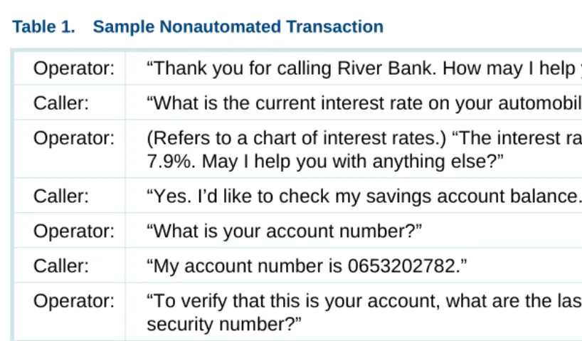
Table 1 on page 4 represents a typical conversation, or transaction, between a caller and an operator at a bank.
Table 1. Sample Nonautomated Transaction
Operator: “Thank you for calling River Bank. How may I help you?” Caller: “What is the current interest rate on your automobile loans?”
Operator: (Refers to a chart of interest rates.) “The interest rate for our auto loans is 7.9%. May I help you with anything else?”
Caller: “Yes. I’d like to check my savings account balance.” Operator: “What is your account number?”
Caller: “My account number is 0653202782.”
Operator: “To verify that this is your account, what are the last four digits of your social security number?”
Caller: “9087”
Operator: “One moment, please.” (Accesses account balance using a computer terminal.) “Your savings account balance is $2,010.27. May I help you with anything else?”
Caller: “Yes. I’d like to speak to someone about an auto loan.”
Types of Interactions Between Caller and Operator
You can better understand how calls are automated if you break down the nonautomated call transactions into its more basic steps.
In the nonautomated sample call (Table 1 on page 4), you can see the following types of interactions between the caller and the operator:
1 The operator greets the caller.
2 The operator prompts the caller and receives a request for information. In the sample call, this includes interest rate and account balance
information.
3 The operator takes the following actions at the caller’s request:
~ If necessary, the operator prompts the caller for further information (type of rate, type of account, ID number, and so forth).
~ The operator looks up the information.
~ The operator reports the information.
4 The operator repeats Step 2 and Step 3.
Operator: “I’ll transfer you to one of our loan office representatives. One moment, please.” (Transfers caller to loan officer, who must then access the computer to gain the customer’s credit history.)
Table 1. Sample Nonautomated Transaction
5 The caller requests information that can only be provided by someone other than the operator.
6 The operator transfers the caller.
Virtually all transactions consist of the basic steps listed above. The caller’s “request for information” shown in Step 2 above may be as simple as the need to hear a checking account balance or the latest stock market value. More complex requests might include placing a sales order or requesting information on a particular product via a fax.
In the sample banking transaction, when the caller asks for an interest rate, the operator simply looks at a chart and reads the information to the caller. However, when the caller wants to know account balance information, the operator must ask for additional information (the caller’s account number and social security number), and then use a computer terminal to enter the caller information and read the balance displayed on the screen.
Finally, when the caller requests information on automobile loans, the operator must transfer the call to a loan officer who has the means to further investigate and service the inquiry.
Automated Transaction Using the System
Types of Interactions Between Caller and System
In an automated call, you can see the following types of interactions between the caller and the system:
1 The system greets the caller.
2 The system prompts the caller and receives a request for information. In the sample call, this includes interest rate and account balance
information.
3 The system takes the following action on the caller request:
~ If necessary, the system prompts the caller for further information (type of rate, type of account, ID number, and so forth). In this sample call, the caller is asked to enter the last four digits of his or her social security number.
~ The system looks up the information from the bank database.
~ The system reports the information to the caller.
4 The system repeats Step 2 and Step 3.
5 The caller requests information that can only be provided by a nonautomated operation.
System Hardware
System software operates on a hardware system called a Multi-Application Platform (MAP). Four different hardware platforms are available as the physical basis of the system. These platforms have different capacities and can present system resources in various configurations. This allows each system to be tailored to match each customer’s projected call volumes and office arrangement.
This hardware platforms are as follows:
• MAP/100C — A central-office rack-mounted hardware platform that accommodates customers who need a system that meets central office telecommunications standards.
• MAP/100P — A deskside or rack-mountable hardware platform that accommodates business customers with moderate to large amounts of system activity.
• MAP/40P — A PC-sized unit, in a deskside tower configuration, that accommodates customers with small or moderate amounts of system activity.
Certain applications require multiple systems to provide transaction automation for cases when the maximum number of simultaneous calls is exceeded for a single platform. Multiple platforms then may be necessary to support increased capacity requirements.
For more detailed information on each platform, as well as supported hardware components, see Chapter 2, Hardware .
System Software
At its most basic level, the system is a computer consisting of controlling and speech processing hardware, a UnixWare operating system, and system application software.
Prerecorded speech files are usually present on the system disk(s). These speech files are used to construct prompting phrases that the system uses to instruct the caller during the automated transaction. The amount of custom application software and speech present on a particular system is based on your specific needs.
System Features
A feature can be either software and/or hardware in nature. It is standard with
each system purchase. Some features require nothing additional to be completely functional. However, some features may require the addition of a
feature package to be more complete or more advanced.
For more detailed information on supported features, see Chapter 4, Features .
Feature Packages
A feature package can be hardware and/or software in nature and provides specific functions that enhance the operation or capacities of the base system. Feature packages are not standard with each system purchase. If you require capabilities beyond what the base system provides, you can purchase one or more feature packages to meet these needs. These optional packages provide enhancements such as data network interfaces or
additional basic hardware resources.
2
Hardware
Overview
This chapter describes V7.0 system hardware, including platform capacities, and supported and orderable devices for:
• Standard system hardware by platform
• Optional system hardware, including circuit cards and peripheral equipment
The information in this chapter:
• Distinguishes between standard and optional system hardware
• Explains the uses of all hardware components
• Presents differences between the hardware components of each of the platforms
In addition, this chapter discusses resource assignments for the described hardware components and provides circuit card maximums by platform. Note: The modular design of the V7.0 system permits the components
the hardware described in this chapter can be or is used simultaneously in a single platform.
The base and optional software running on the platform controls the operation of the equipment. The software associated with some of the hardware components is listed and described in Chapter 3, Software. The features and feature packages associated with some hardware components are described in detail in Chapter 4, Features, and Chapter 5, Feature Packages.
Standard System Hardware by Platform
Regardless of the type of application or features being supported, all platforms require a minimum set of hardware components to function properly. The V7.0 system can operate on four different multi-application platforms (MAPs). Platforms covered include:
• MAP/100C on page 13
• MAP/100P on page 22
• MAP/40P on page 34
• MAP/5P on page 42
MAP/100C
Standard System
Hardware The MAP/100C is a central-office rack-mounted unit. It is used primarily to provide services that enhance the functionality of large central office
telecommunication switches and services operated by local and long-distance telephone companies. The MAP/100C can be mounted in either a 24-inch 4ESS® or 5ESS® equipment rack. It cannot be mounted in an equipment rack used to mount the MAP/100P unit.
The following standard hardware components for the MAP/100C are discussed:
• Backplane on page 13
• Standard Circuit Cards on page 14
• Standard Bus Cables on page 16
• Peripheral Devices on page 17
• Power Supply on page 18
The backplane configuration supported in the MAP/100C for V7.0 is an ISA/PCI backplane. This backplane has a total of 24 slots, consisting of 1 dedicated CPU slot (a PCI/ISA combination), 20 ISA slots, and 3 PCI slots. This backplane replaces the older, full ISA backplane without PCI slots. Of the 20 ISA slots, one slot is usually occupied by a remote maintenance circuit card, and the 19 remaining ISA slots are available for voice response and voice processing cards, as well as for cards to support local area networks, and so on. Of the three PCI slots, one slot is dedicated to the video circuit card, one is for PCI LAN, and the remaining slot is available for a second PCI LAN or other PCI cards.
The MAP/100C platform is equipped with six half-height disk bays. In the standard configuration, one half-height bay is occupied by the cartridge tape drive, and another is occupied by a hard disk drive, with four bays remaining.
Standard Circuit
Cards Standard circuit cards provide the central processing, video, and peripheral functions, and certain basic communication functions of the system.
In the MAP/100C, all circuit cards are mounted vertically with all I/O interface cables exiting from the top of the platform. A hinged door on the front of the platform provides access to the circuit cards and backplane.
The following standard circuit cards in the MAP/100C are discussed:
• Central Processing Unit Circuit Card on page 15
• External SCSI Connector on page 15
• Video Controller Circuit Card on page 15
• Remote Maintenance Circuit Card on page 16
Central Processing Unit Circuit Card
The central processing unit (CPU) circuit card for the MAP/100C for V7.0 is a P5 processor operating at 200-MHz with a minimum of 64 MB of RAM and a maximum of 128 MB of RAM.
External SCSI Connector
The external small computer system interface (SCSI) connector provides access to the SCSI bus that is external to the MAP/100C. When the SCSI connector is not used for access purposes, an active termination must be plugged on for terminating the SCSI bus. A PS/2 mouse connector is provided but not supported. The CONVERSANT V7.0 system supports a serial mouse only.
Video Controller Circuit Card
Remote Maintenance Circuit Card
The remote maintenance circuit card provides a method of remote monitoring and access for offsite technicians. This circuit card has a built-in 28.8 modem for all systems in the United States.
Standard Bus Cables
The following two types of standard bus cables for the MAP/100C system are discussed:
• SCSI Bus Cable on page 16
• TDM Bus Cable on page 16
SCSI Bus Cable
The SCSI bus cable serves as the interface from the SCSI controller to SCSI devices, such as the hard disk drive and tape devices.
TDM Bus Cable
The TDM bus cable is used by the voice processing cards (tip/ring, T1/ E1, and SSP) when they send digitized speech to other cards in the system. For example, it is used to connect SSP resources to telephone network
connections for speech playback, voice coding, speech recognition, or for bridging one telephone connection to another.
Peripheral Devices V7.0 system platforms support storage devices including hard disk, diskette, and cartridge tape drives. The MAP/100C is supplied with data storage and transfer devices in the SCSI format.
For more information on the capabilities and use of SCSI peripherals, see Guidelines for the Addition of SCSI Devices on page 73 and Chapter 4, Features.
The following peripheral devices supported by the MAP/100C platform are discussed:
• Hard Disk Drive on page 17
• Diskette Drive on page 18
• Cartridge Tape Drive on page 18
Hard Disk Drive
A hard disk drive is a peripheral device used to provide storage of and random access to large amounts of data for the system. This data can include the operating system, application software, speech data, and database tables.
Diskette Drive
The diskette drive is a peripheral device used to load and back up system software. All new MAPs include a single diskette drive. This unit uses standard 3.5-inch, 1.44-MB, high-density diskettes. It is located in the front chassis area and is accessible from the user interface panel.
Cartridge Tape Drive
The cartridge tape drive is a peripheral device used to back up and restore files using a tape cartridge, thereby eliminating the need to install and back up files using diskettes. A single cartridge tape can store up to 2-Gbytes of information.
All new V7.0 MAPs include a single 2-GB, SCSI-format cartridge tape drive. It is located below the diskette drive, inside the disk bay.
Power Supply The MAP/100C is available in a -48 VDC power supply.
Views of the MAP/100C
• Figure 1 on page 19 shows the front view of the MAP/100C.
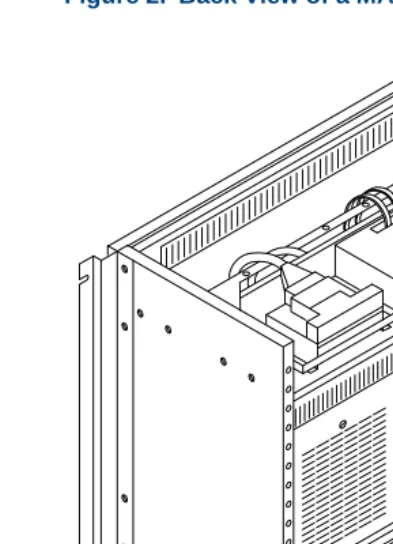
• Figure 2 on page 20 shows the back view.
Figure 1. Front View of a MAP/100C with 4ESS Side-Mounting Brackets
Power
Floppy Disk Drive
Off On Reset
ESD Ground 1234
Drive Bay Fan Status
Pwr Sup
CPU Rear Fans Serial Port Video
MAP/100P
Standard System
Hardware The MAP/100P is available as a freestanding desk-side unit. It is equipped with four casters that allow you to roll the chassis around as required. The
MAP/100P can also be ordered as a rack-mounted unit (a factory-installed component). Multiple units can only be mounted in a 19-inch-panel commercial equipment rack. The MAP/100P cannot be mounted in the equipment racks used to mount the MAP/100C.
The platform consists of one physical unit with three main areas: the card backplane, a peripheral bay (disk bay), and power supply units mounted in the rear.
The following standard hardware components for the MAP/100P are discussed:
• Backplane on page 23
• Standard Circuit Cards on page 24
• Standard Bus Cables on page 25
• TDM Bus Cable on page 26
• Peripheral Devices on page 26
Backplane Each platform contains a backplane that provides circuit card mounting positions called slots. The MAP/100P has a PCI/ISA backplane that resides inside the chassis. This backplane is installed in all new V7.0 systems. It has a total of 20 slots, consisting of 1 dedicated CPU slot, 16 ISA slots, and 3 PCI slots.
Of the 16 ISA slots, one slot is occupied by a remote maintenance circuit card. The 15 remaining ISA slots are available for voice response and voice processing cards, and so on.
Of the three PCI slots, one slot is dedicated to the video circuit card. The remaining two are available for a PCI LAN circuit card, a RAID controller circuit card, or other PCI cards.
Standard Circuit Cards
Standard circuit cards provide the standard central processing, video, and peripheral functions, and certain basic communication functions of the system.
In the MAP/100P deskside unit, all circuit cards are mounted horizontally with the PCI cards at the top. Any I/O interface cables exit from the back of the platform. An access panel on the left side of the platform provides entry to the backplane. In the MAP/100P rack-mounted unit, all circuit cards are installed vertically with the PCI cards to the right. The access panel is located on the top of the unit.
For more information about software associated with the following circuit cards, see Chapter 4, Features and Chapter 5, Feature Packages. The following standard circuit cards in the MAP/100P are discussed:
• Central Processing Unit Circuit Card on page 24
• Video Controller Circuit Card on page 25
• Remote Maintenance Circuit Card on page 25
Central Processing Unit Circuit Card
Video Controller Circuit Card
The video controller circuit card provides the interface between the system processor and the video monitor. For the MAP/100P, this circuit card is a PCI bus circuit card.
Remote Maintenance Circuit Card
The remote maintenance circuit card provides a method of remote monitoring and access for off-site technicians. This circuit card has a built-in 28.8 modem for all systems in the U.S.
Standard Bus
Cables The following two types of standard bus cables for the MAP/100P system are discussed:
• SCSI Bus Cable on page 16
• TDM Bus Cable on page 16
SCSI Bus Cable
TDM Bus Cable
The TDM bus cable is used by the voice processing cards (tip/ring, T1/ E1, and SSP) when they send digitized speech to other cards in the system. For example, it is used to connect SSP resources to telephone network
connections for speech playback, voice coding, speech recognition, or for bridging one telephone network connection to another. A TDM bus cable is supplied with each V7.0 system purchased.
Peripheral Devices V7.0 system platforms support storage devices including hard disk, diskette, and cartridge tape drives. The MAP/100P is supplied with data
storage/transfer devices in the Small Computer System Interface (SCSI) format.
For more information on the capabilities and use of SCSI peripherals, see Guidelines for the Addition of SCSI Devices on page 73 and Chapter 4, Features.
The following peripheral devices supported by the MAP/100P platform are discussed:
• Hard Disk Drive on page 27
• Diskette Drive on page 27
• Cartridge Tape Drive on page 27
Hard Disk Drive
A hard disk drive is a peripheral device used to provide storage and random access to large amounts of data within the system. This data can include the operating system, application software, speech data, and database tables. All new MAP/100P platforms are equipped with at least one 2-GB Single Connector Architecture (SCA)-SCSI hard-disk drive. If the system is equipped with a RAID controller card, at least three hard disk drives are provided. The MAP/100P can support up to six SCA-SCSI hard disk drives. The disks are mounted in the drive bay; orientation of the disk and drive bays is determined by the type of unit (deskside or rack-mounted).
Diskette Drive
The diskette drive is a peripheral device used to load and back up system software. All new MAPs include a single diskette drive. This unit uses standard 3.5-inch, 1.44-MB, high-density diskettes. It is located in peripheral bay position 4.
Cartridge Tape Drive
The cartridge tape drive is a peripheral device used to back up and restore files from a tape cartridge. This unit eliminates the need to install and back up files using diskettes and thus streamlines the process. A single cartridge tape can store up to 2-GB of information.
External SCSI Connector
On the MAP/100P, a P5200 CPU SCSI controller provides an interface to an external SCSI connector. When the SCSI connector is not used for access purposes, an active termination must be plugged on for terminating the SCSI bus. External SCSI devices are installed only for maintenance purposes and are not supported for permanent connection.
Because of the faster, wide SCSI bus speed, special requirements exist for connecting external hardware.
Power Supply All new sales of the MAP/100P are supplied with two AC (110V/220V) hot-swappable power supply modules. An external uninterruptable power supply (UPS) can be ordered.
Views of the MAP/100P
• Figure 4 on page 29 shows the front view of a deskside MAP/100P.
• Figure 5 on page 30 shows the back view of a deskside MAP/100P.
• Figure 6 on page 31 shows the front view of a rack-mounted MAP/100P.
• Figure 7 on page 32 shows the back view of a rack-mounted MAP/100P.
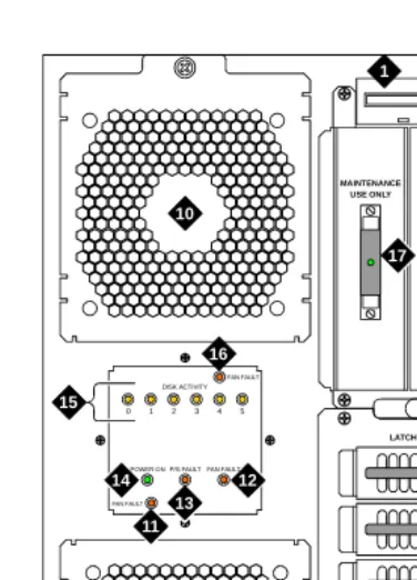
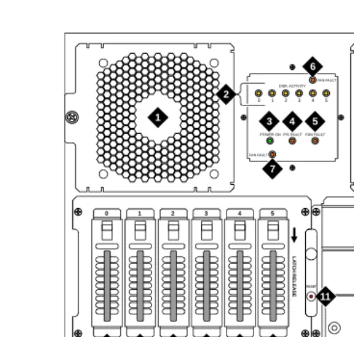
Figure 4. Front View of a Deskside MAP/100P
scinp002 klc 011198
1 2 3 10 10 15 FAN FAULT FAN FAULT
POWER ONP/S FAULT FAN FAULT DISK ACTIVITY 0 1 2 3 4 5
MAINTENANCE USE ONLY R E SET LATCH RELEASE 0 1 2 3 4 5 16 14 13 12 11 17 4 5 6 7 8 9
1. Diskette drive
2. Cartridge tape drive
3. Reset push button
4. Hard disk drive 0
5. Hard disk drive 1
6. Hard disk drive 2
7. Hard disk drive 3
8. Hard disk drive 4
9. Hard disk drive 5
10.Circuit card cage fan
11.Fan fault LED for lower fan
12.System fan fault LED
13.Power supply fault LED
14.Power on LED
15.Disk activity indicator (per SCSI ID)
16.Fan fault LED for upper fan
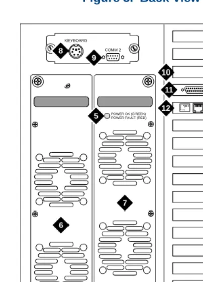
Figure 5. Back View of a Deskside MAP/100P
scinp003 KLC 032398
4
KEYBOARD
9
POWER OK (GREEN) POWER FAULT (RED)
POW ER OK (G REE N) POW ER FAU LT (RED ) 7 6 AYC54 Lu cent COMM 2 1 2 3 5 5 8 10 12 11
1. AC Line fuse
2. Line fuse rating label
3. AC power inlet receptacle
4. ON/OFF power switch with protective guard
5. Power supply status LED
6. Power supply 1
7. Power supply 2
8. Keyboard connector
9. COM2 port
10.Video circuit card (PCI slot 1)
11.P5 200 MHz CPU with COM1 (slot 17)
Figure 6. Front View of a Rack-Mounted MAP/100P
scinp007 KLC 021798
1 1 10 5 4 3 2 1 0 FAN FAULT FAN FAULT POWER ON P/S FAULTFAN FAULT
DISK ACTIVITY
0 1 2 3 4 5
RESET L A T C H R EL EA SE 2 7 6 4 5 3 8 9 11 12 13 15 16 14 17
1. Circuit card cage fan assembly
2. Disk activity indicator (per SCSI ID)
3. Power on LED
4. Power supply fault LED
5. Card cage fan fault LED
6. Fan fault LED for right fan
7. Fan fault LED for left fan
8. SCSI external active terminator
9. Diskette drive
10.Cartridge tape drive
11.Reset push button
12.Hard disk drive 5
13.Hard disk drive 4
14.Hard disk drive 3
15.Hard disk drive 2
16.Hard disk drive 1
Figure 7. Back View of a Rack-Mounted MAP/100P
6
scinp006 KLC 032398
KE YB O A R D AYC54 Lucent CO M M 2 7 8 9 10 4 1 3 2 5 5 PO W E R O K (GRE E N) PO W E R FA U L T (R ED) PO W E R O K (GR EE N) PO W E R F AULT (R ED ) 11 12
1. Line fuse
2. Line fuse rating label
3. AC power inlet receptacle
4. ON/OFF power switch with protective guard
5. Power supply status LED
6. Power supply 1
7. Power supply 2
8. Keyboard connector
9. COM2 port
10.Video circuit card (PCI slot 1)
11.P5 200 MHz CPU with COM1 (slot 17)
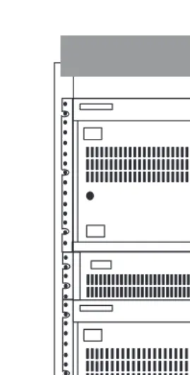
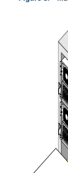
Figure 8. Multiple Rack-Mounted MAP/100Ps, Front View
MAP/40P
Standard System
Hardware The MAP/40P platform is a desk-side (tower), PC-sized unit designed for use in a typical office setting.
The following standard hardware components for the MAP/40P are discussed:
• Backplane on page 34
• Standard Circuit Cards on page 35
• Standard Bus Cables on page 36
• Peripheral Devices on page 37
• Power Supply on page 39
Backplane Each platform contains a backplane that provides circuit card mounting positions called slots. The MAP/40P has a PCI/ISA backplane that resides inside the left side of the chassis. This backplane is installed in all new V7.0 systems and has a total of 13 slots, consisting of 1 dedicated CPU slot, 9 ISA slots, and 3 PCI slots.
Of the three PCI slots, one slot is dedicated to the video circuit card. The remaining two are available for PCI LAN or other PCI cards.
Standard Circuit
Cards Standard circuit cards provide the standard central processing, video, and peripheral functions, and certain basic communication functions of the
system.
In the MAP/40P, all circuit cards are mounted horizontally with the PCI cards to the top and I/O interface cables exiting from the back of the platform. Access to the backplane is provided by removing an exterior dress cover. For more information about software associated with the standard circuit cards, see Chapter 4, Features and Chapter 5, Feature Packages. The following standard circuit cards in the MAP/40P are discussed:
• Central Processing Unit Circuit Card on page 35
• External SCSI Connector on page 36
• Video Controller Circuit Card on page 36
• Remote Maintenance Circuit Card on page 36
Central Processing Unit Circuit Card
External SCSI Connector
The external SCSI connector provides an external SCSI connection. When the SCSI connector is not used for access purposes, an active termination must be plugged on for terminating the SCSI bus. A PS/2 mouse connector is provided but not supported. The CONVERSANT V7.0 system supports a serial mouse only.
Video Controller Circuit Card
The video controller circuit card provides the interface between the system processor and the video monitor. For the MAP/40P, this circuit card is a PCI bus circuit card.
Remote Maintenance Circuit Card
The remote maintenance circuit card provides a method of remote monitoring and access for offsite technicians. This circuit card has a built-in 28.8 modem for all systems in the United States.
Standard Bus Cables
The following two types of standard bus cables for the MAP/40P system are discussed:
• SCSI Bus Cable on page 37
SCSI Bus Cable
The SCSI bus cable serves as the interface from the SCSI controller to SCSI devices such as a hard disk drive or tape drive.
TDM Bus Cable
The TDM bus cable is used by the voice processing cards (tip/ring, T1/ E1, and SSP) when they send digitized speech to other cards in the system. For example, it is used to connect SSP resources to telephone network
connections for speech playback, voice coding, speech recognition, or for bridging one telephone connection to another. A TDM bus cable is supplied with each V7.0 system.
Peripheral Devices V7.0 system platforms support storage devices including hard disk, diskette, and cartridge tape drives. The MAP/40P is supplied with data
storage/transfer devices in the Small Computer System Interface (SCSI) format.
For more information on the capabilities and use of SCSI peripherals, see Guidelines for the Addition of SCSI Devices on page 73 and Chapter 4, Features.
The following peripheral devices supported by the MAP/40P platform are discussed:
• Hard Disk Drive on page 38
• Diskette Drive on page 38
Hard Disk Drive
A hard disk drive is a peripheral device used to provide storage of and random access to large amounts of data within the system. This data can include the operating system, application software, speech data, and database tables.
All new MAP/40P platforms are equipped with at least one 2-GB SCSI hard disk drive. The MAP/40P can support up to two SCSI hard disk drives. These disks are mounted in the peripheral bay behind the front-mounted air filter and in front of the cooling fans.
Diskette Drive
The diskette drive is a peripheral device used to load and back up system software. All new MAP/40Ps include a single diskette drive. This unit uses standard 3.5-inch, 1.44-MB, high-density diskettes. It is located in the front behind the swinging door.
Cartridge Tape Drive
All new V7.0 MAPs include a single 2-GB, SCSI-format cartridge tape drive. A swinging door provides access. Tapes can be purchased from several different vendors.
Power Supply The MAP/40P operates from an autoswitching 110/220 VAC power supply.
Views of the MAP/40P
• Figure 9 on page 40 shows the front view of the MAP/40P.
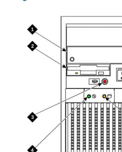
Figure 9. Front View of the MAP/40P
h2mxfnt3 KLVC 081997
1
2
3
4 5
6
1. Cartridge tape drive
2. Diskette drive
3. Power indicator
4. Disk activity indicator
5. Reset switch
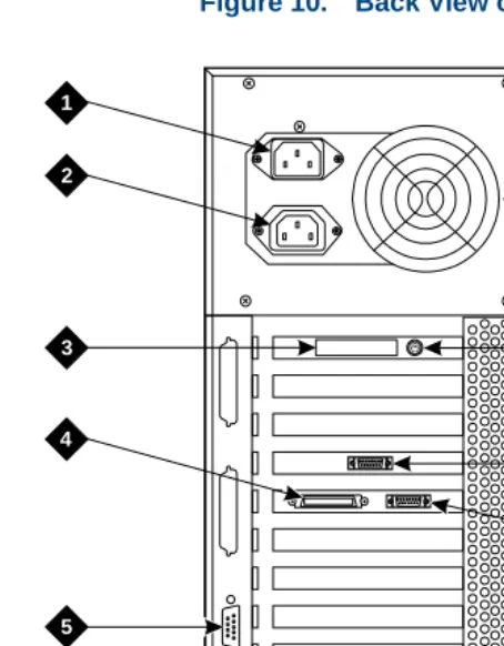
Figure 10. Back View of the MAP/40P
h2mxrear KLC 081997
1
2
3
4
6
7
8
9
10
5
1. AC power inlet receptacle
2. AC power supply outlet
3. External SCSI I/O connector
4. Parallel port
5. COM2
6. Keyboard connector
7. Power supply fan exhaust
8. Mouse connector
9. Video connector
MAP/5P
Standard System
Hardware The MAP/5P platform is a deskside unit in a mini-tower configuration. It is a PC-sized unit designed for use in a typical office setting.
The following standard hardware components of the MAP/5P are discussed:
• Riser Card on page 42
• Motherboard on page 43
• Standard Circuit Cards on page 43
• Standard Bus Cables on page 44
• Peripheral Devices on page 45
• Power Supply on page 46
Motherboard The MAP/5P motherboard contains:
• P5 200 MHz CPU
• Video interface
• Keyboard connector
• Mouse connector
• Two serial ports and one parallel port
• 64 MB of memory
• Riser card connector
Standard Circuit
Cards Standard circuit cards provide certain basic communication functions of the system. In the MAP/5P, all circuit cards are mounted horizontally with any
interface cables exiting from the back of the platform. Access to the riser card is provided by removing an exterior dress cover.
The following standard circuit cards for the MAP/5P are discussed:
• SCSI Controller Circuit Card on page 44
• Remote Maintenance Circuit Card on page 44
SCSI Controller Circuit Card
The SCSI controller circuit card is a PCI card. It provides an interface between the system processor located on the motherboard and any SCSI peripheral devices.
Remote Maintenance Circuit Card
The remote maintenance circuit card provides a method of remote monitoring and access for offsite technicians. This circuit card has a built-in 28.8 modem for all systems in the United States.
Standard Bus Cables
There following two types of standard bus cables for the MAP/5P system are discussed:
• SCSI Bus Cable on page 44
• TDM Bus Cable on page 44
SCSI Bus Cable
The SCSI bus cable serves as the interface from the SCSI controller to SCSI devices such as a hard disk drive or tape drive.
TDM Bus Cable
Peripheral Devices V7.0 system platforms support storage devices including hard disk, diskette, and cartridge tape drives. The MAP/5P is supplied with data storage/transfer devices in the Small Computer System Interface (SCSI) format.
For more information on the capabilities and use of SCSI peripherals, see Guidelines for the Addition of SCSI Devices on page 73 and Chapter 4, Features.
The following peripheral devices supported by the MAP/5P platform are discussed:
• Hard Disk Drive on page 45
• Diskette Drive on page 46
• Cartridge Tape Drive on page 46
Hard Disk Drive
Diskette Drive
The diskette drive is a peripheral device used to load and back up system software. All new MAP/5Ps include a single diskette drive. This unit uses standard 3.5-inch, 1.44-MB, high-density diskettes. It is accessible from the front behind a swinging door.
Cartridge Tape Drive
The cartridge tape drive is a peripheral device used to back up and restore files using a tape cartridge, thereby eliminating the need to install and back up files using diskettes. A single cartridge tape can store up to 2-Gbytes of information.
All new V7.0 MAPs include a single 2-Gbyte, SCSI-format cartridge tape drive. Tapes can be purchased from several different vendors.
The cartridge tape drive is located in bay position 1 of the MAP/5P behind the swinging door.
Power Supply The MAP/5P operates from a switchable 110/220 VAC power supply.
Views of the MAP/5P
• Figure 11 on page 47 shows the front view of the MAP/5P.
Figure 11. Front View of the MAP/5P with Dress Cover Removed
sccvfv1 RPY 101497
1
2
3
4 5 6 7 8
1. Cartridge tape drive
2. Diskette drive
3. Circuit card cage fan
4. Reset switch
5. Power switch
6. Power indicator
7. Speed indicator
Figure 12. Back View of the M