ABSTRACT
MONTESDEOCA SOLORZANO, OSCAR FABRICIO. Basic Characteristics of Grancrete HFR. (Under the direction of Dr. Sami Rizkalla).
Grancrete™ is a novel cementitious material originally developed at Argonne National Laboratories and consist of a family of magnesium phosphate cement (MPC) products. The objective of this thesis is to examine the basic characteristics of one type of Grancrete named Grancrete HFR (High Fire Resistant) which is basically a Fiber-Reinforced Magnesium Potassium Phospho-Silicate Cement. The research program included a comprehensive experimental program to evaluate the fundamental properties of the fresh mixture of Grancrete HFR paste, the mechanical properties of the hardened Grancrete HFR paste, and the bond characteristics of Grancrete HFR paste to selected construction materials.
The reaction of Grancrete HFR powder and water is exothermic. Test results indicate that the setting time of Grancrete HFR paste is less than 10 minutes, and the pH level of the fresh paste is close to 7. Typical values of compressive strength of the paste at 28 days range between 6,000 to 10,000 psi, and more than 50% of this strength was achieved within the first 24 hours of air curing. The measured ultimate strain ranges between 0.006 and 0.008. The modulus of elasticity is between 1650 and 1950 ksi. The modulus of rupture is
Basic Characteristics of Grancrete HFR
by
Oscar Fabricio Montesdeoca Solorzano
A thesis submitted to the Graduate Faculty of North Carolina State University
in partial fulfillment of the requirements for the degree of
Master of Science
Civil Engineering
Raleigh, North Carolina
2008
APPROVED BY:
DEDICATION
Para mis padres: Ángel M. Montesdeoca y
Janeth Solórzano
To my parents: Ángel M. Montesdeoca and
BIOGRAPHY
Oscar Fabricio Montesdeoca Solórzano was born in Manabí, Ecuador on September 23th 1981. He received his B.S. in Civil Engineering in 2004 from Escuela Politécnica Nacional in Quito, Ecuador. Upon graduation, he was award the Engineering and Sciences Schools Diploma for the highest standing in his graduation ceremony. Then, he worked for few years as a Civil Engineer in some projects in his country, Ecuador. In 2006, he started his studies towards his Master of Science degree in Civil Engineering with concentration in
ACKNOWLEDGMENTS
I would like to thank my advisor Dr. Sami Rizkalla for his guidance, patience and especially for the extraordinary opportunity that he gave me to work under his guidance during this research project. I extend my gratitude to Dr. Michael Leming and Dr. Paul Zia for serve as members of my committee and to provide also guidance during this project and share with me all their knowledge and experience. I also wish to thank Mr. Roberto Nunez for all his advice and help during the entire program.
I would like to also thank the Constructed Facilities Laboratory in the persons of Mr. Jerry Atkinson and Mr. William Dunleavy for their invaluable technical assistance. Special thanks to all my fellow graduate students at the Constructed Facilities Laboratory and Mann Hall for their help and friendship.
I would like to acknowledge the financial support and materials provided by Grancrete, Inc. Acknowledge also to the National Science Foundation through the RB2C Center.
TABLE OF CONTENTS
LIST OF TABLES ... ix
LIST OF FIGURES ... x
1 INTRODUCTION ... 1
1.1 Background ... 1
1.2 Objectives ... 2
1.3 Scope ... 2
2 BACKGROUND ... 5
2.1 Introduction ... 5
2.1.1 Ceramics and hydraulic cements ... 7
2.1.2 Chemically Bonded Ceramics/Cements (CBCs) ... 8
2.1.3 Chemically Bonded Phosphate Ceramics/Cements (CBPCs)... 10
2.2 Magnesium Phosphate Cements (MPC) ... 11
2.2.1 Retarders for MPC ... 12
2.3 Magnesium Potassium Phosphate Ceramic/Cement (Ceramicrete) ... 14
2.3.1 CBPCs Matrix Composites ... 15
2.3.2 Phospho-Silicate Ceramicrete ... 17
2.3.3 Fiber Reinforcement of CBPC Products ... 19
2.4 Grancrete HFR... 20
2.4.1 Magnesium Oxide (MgO) ... 21
2.4.2 Monopotassium Phosphate (KH2PO4) ... 21
2.4.3 Calcium Silicate {Wollastonite} (CaSiO3)... 22
2.4.4 Polyethylene Fibers ... 23
2.5 Research Significance... 23
3 PRELIMINARY WORK ... 25
3.2.2 Portland cement ... 26
3.2.3 Metakaolin ... 26
3.2.4 Vermiculite ... 27
3.3 Development of Mixing Procedure ... 28
3.3.1 Mixing procedure used in the preliminary work... 28
3.3.2 Mixing procedure used after the preliminary work... 29
3.4 Effect of water-to-Grancrete ratio on Compressive Strength ... 30
3.5 Effect of water-to-Grancrete ratio on workability ... 32
3.6 Selection of potential mixtures for construction applications ... 37
3.7 Microscopic and Chemical Analysis ... 38
4 PROPERTIES OF THE FRESH MIXTURE OF GRANCRETE HFR ... 45
4.1 Introduction ... 45
4.2 Setting Time ... 45
4.2.1 Experimental Program ... 46
4.2.2 Test Apparatus and Procedure ... 46
4.2.3 Test Data and Analysis ... 48
4.3 Temperature Monitoring ... 51
4.3.1 Experimental Program ... 51
4.3.2 Test Apparatus and Procedure ... 52
4.3.3 Test Data and Analysis ... 54
4.4 Setting pH Level ... 59
4.4.1 Experimental Program ... 59
4.4.2 Test Apparatus and Procedure ... 60
4.4.3 Test Data and Analysis ... 60
5 PROPERTIES OF HARDENED GRANCRETE HFR ... 62
5.1 Introduction ... 62
5.2 Compression Properties ... 62
5.2.1 Experimental Program ... 63
5.2.2 Test Apparatus and Procedure ... 64
5.2.3 Test Data and Analysis ... 70
5.3 Flexural Properties ... 88
5.3.2 Test Apparatus and Procedure ... 88
5.3.3 Test Data and Analysis ... 91
5.4 Water Absorption ... 93
5.4.1 Experimental Program ... 93
5.4.2 Test Apparatus and Procedure ... 95
5.4.3 Test Data and Analysis ... 101
5.5 Shrinkage and Coefficient of Thermal Expansion ... 122
5.5.1 Experimental Program ... 122
5.5.2 Test Apparatus and Procedure ... 123
5.5.3 Test Data and Analysis ... 130
6 BOND CHARACTERISTICS OF GRANCRETE HFR ... 136
6.1 Introduction ... 136
6.2 Experimental Program ... 136
6.3 Test Apparatus and Procedure ... 139
6.4 Test Data and Analysis ... 144
7 CONCLUSIONS ... 150
7.1 Conclusions of the Preliminary work ... 150
7.2 Conclusions of the study of the fresh properties of Grancrete HFR ... 152
7.3 Conclusions of the study of the Hardened Grancrete HFR ... 153
7.3.1 Compressive Properties ... 153
7.3.2 Flexural Properties... 154
7.3.3 Water Absorption, Density and Voids ... 154
7.3.4 Shrinkage and Coefficient of Thermal Expansion ... 155
7.4 Conclusions of the study of the bond characteristics of Grancrete HFR... 155
7.5 Summary of the basic properties for Grancrete HFR paste ... 157
7.6 Future Research ... 158
REFERENCES ... 159
APPENDIX A: COMPRESSION PROPERTIES ... 167
APPENDIX B: FLEXURAL PROPERTIES ... 182
LIST OF TABLES
TABLE 2.1:PROPERTIES OF WOLLASTONITE-FILLED CERAMICRETE [WAGH,2004] ... 18
TABLE 3.1:EFFECT OF W/G RATIO IN COMPRESSIVE STRENGTH AT 3 DAY-OLD ... 31
TABLE 3.2:EFFECT OF W/G RATIO ON FLOWABILITY OF FRESH GRANCRETE HFR PASTE ... 34
TABLE 4.1:SETTING TIME TEST MATRIX ... 46
TABLE 4.2:FORCES REQUIRED TO REACH INITIAL AND FINAL SETTING TIMES BY NEEDLE ... 47
TABLE 4.3:SETTING TIME BY PENETRATION RESISTANCE,MIXTURE #1(W/G=0.20) ... 49
TABLE 4.4:SETTING TIME BY PENETRATION RESISTANCE,MIXTURE #2(W/G=0.25)... 50
TABLE 4.5:TEMPERATURE MONITORING TEST MATRIX ... 52
TABLE 4.6:TEMPERATURE MONITORING FINDINGS ... 59
TABLE 4.7: PH AND TEMPERATURE DURING SETTING OF GRANCRETE HFR PASTE ... 61
TABLE 5.1:MIXTURES TESTED FOR COMPRESSION PROPERTIES ... 63
TABLE 5.2:DETAILS OF MIXTURES EVALUATED FOR COMPRESSIVE STRENGTH ... 64
TABLE 5.3:COMPRESSIVE STRENGTH TEST RESULTS USING 2-IN CUBES ... 72
TABLE 5.4:COMPRESSIVE STRENGTH TEST RESULTS USING 4” BY 8” CYLINDERS ... 76
TABLE 5.5:MODULUS OF ELASTICITY FOR GRANCRETE HFR PASTE ... 85
TABLE 5.6:MODULUS OF RUPTURE USING 3X3X12-IN PRISM SPECIMENS ... 91
TABLE 5.7:WATER ABSORPTION TEST MATRIX ... 94
TABLE 5.8:STANDARD CALCULATION OF ABSORPTION,DENSITY AND VOIDS ... 108
TABLE 5.9:DENSITY BASED CALCULATION OF ABSORPTION,DENSITY AND VOIDS ... 108
TABLE 5.10:STANDARD CALCULATIONS FOR ABSORPTION AND VOIDS ... 112
TABLE 5.11:DENSITY BASED CALCULATIONS FOR ABSORPTION AND VOIDS ... 112
TABLE 5.12:CALCULATIONS FOR BULK DENSITY AND APPARENT DENSITY ... 116
TABLE 5.13:SHRINKAGE AND COEFFICIENT OF THERMAL EXPANSION TEST MATRIX ... 123
TABLE 5.14:COEFFICIENT OF THERMAL EXPANSION OF GRANCRETE HFR,ASTMC531 ... 134
TABLE 5.15:COEFFICIENT OF THERMAL EXPANSION OF GRANCRETE HFR,AASHTOTP60MOD. ... 135
TABLE 6.1:SUBSTRATES AND OVERLAYS USED IN PULL-OFF TEST ... 138
TABLE 6.2:BOND STRENGTH OF GRANCRETE HFR WITH TRADITIONAL CONSTRUCTION MATERIALS ... 144
TABLE 7.1:SUMMARY OF PROPERTIES FOR GRANCRETE HFR PASTE. ... 157
TABLE A.1–A.6: TABLES OF VALUES OF COMPRESSIVE STRENGTH, FG(CUBE), FOR EACH SPECIMEN AND AVERAGE VALUES AND STANDARD DEVIATION OF EACH SERIES USING 2-IN CUBE SPECIMENS. ... 167
TABLE A.7–A.8: TABLES OF VALUES OF COMPRESSIVE STRENGTH, FG(CYL.),MODULUS OF ELASTICITY,E, AND ULTIMATE STRAIN,U, FOR EACH SPECIMEN AND AVERAGE VALUES OF EACH SERIES USING 4” BY 8” CYLINDER SPECIMENS. ... 167
FIGURE A.1–A.12:STRESS-STRAIN RELATIONSHIP FOR EACH SERIES. ... 167
TABLE B.1–B.2: TABLES OF VALUES OF MODULUS OF RUPTURE (FLEXURAL STRENGTH) FOR EACH SPECIMEN AND AVERAGE VALUES AND STANDARD DEVIATION OF EACH SERIES. ... 182
LIST OF FIGURES
FIGURE 2.1:GRANCRETE HFR“FAMILY TREE” 6
FIGURE 3.1:EFFECT OF W/G RATIO ON COMPRESSIVE STRENGTH AT 3 DAY-OLD 32
FIGURE 3.2:FLOW TABLE AND MOLD 33
FIGURE 3.3:FLOW TEST 34
FIGURE 3.4EFFECT OF W/G RATIO ON COMPRESSIVE STRENGTH AND FLOW OF GRANCRETE HFR 36
FIGURE 3.5:EDX OF GRANCRETE HFR PASTE (I) 39
FIGURE 3.6:EDX OF GRANCRETE HFR PASTE (II) 40
FIGURE 3.7:EDX OF GRANCRETE HFR PASTE (III) 40
FIGURE 3.8:EDX OF GRANCRETE HFR PASTE (IV) 41
FIGURE 3.9:GRANCRETE HFR PASTE EDXSPECTRA 42
FIGURE 3.10:PORTLAND CEMENT TYPE II PASTE EDXSPECTRA 42
FIGURE 3.11:SCANNING ELECTRON MICROGRAPH OF GRANCRETE HFR PASTE (MAG.2500X) 43 FIGURE 3.12:SCANNING ELECTRON MICROGRAPH OF GRANCRETE HFR PASTE (MAG.180X) 44
FIGURE 4.1:TEST OF SETTING TIME BY PENETRATION RESISTANCE 48 FIGURE 4.2:SETTING TIME BY PENETRATION RESISTANCE,MIXTURE #1 49 FIGURE 4.3:SETTING TIME BY PENETRATION RESISTANCE,MIXTURE #2 50 FIGURE 4.4:TEMPERATURE MONITORING SET UP (USING 2-IN CUBES) 53 FIGURE 4.5:TEMPERATURE VS.TIME,MIXTURE #1(USING 4” BY 8” CYLINDERS) 54 FIGURE 4.6:TEMPERATURE VS.TIME,MIXTURE #2(USING 4” BY 8” CYLINDERS) 55
FIGURE 4.7:TEMPERATURE VS.TIME (USING 4” BY 8” CYLINDERS) 56 FIGURE 4.8:TEMPERATURE VS.TIME,MIXTURE #1(USING 2-IN CUBES) 57
FIGURE 4.9:TEMPERATURE VS.TIME (MIXTURE #1 W/G=0.20) 58
FIGURE 4.10:CHECKER PH TESTER 60
FIGURE 5.1:COMPRESSIVE STRENGTH TESTING USING 2-IN CUBES 66
FIGURE 5.2:SIDE VIEW OF COMPRESSOMETER 68
FIGURE 5.3:TOP VIEW OF COMPRESSOMETER 68
FIGURE 5.4:MODULUS OF ELASTICITY TEST SET UP 69
FIGURE 5.5:COMPRESSIVE STRENGTH GAIN IN TIME USING 2-IN CUBES 73
FIGURE 5.6:FINISHING OF MIXTURE #5 CUBES 74
FIGURE 5.7:COMPRESSIVE STRENGTH-TIME FOR MIXTURES PREPARED USING VERMICULITE 74
FIGURE 5.8:COMPRESSIVE STRENGTH GAIN IN TIME USING 4”BY 8” CYLINDERS 76
FIGURE 5.9:TYPICAL FAILURE OF CYLINDER SPECIMENS @3 HRS 77
FIGURE 5.10:TYPICAL FAILURE OF CYLINDER SPECIMENS @1 DAY 77 FIGURE 5.11:TYPICAL FAILURE OF CYLINDER SPECIMENS @3 DAYS 78 FIGURE 5.12:TYPICAL FAILURE OF CYLINDER SPECIMENS @7 DAYS 78
FIGURE 5.13:TYPICAL FAILURE OF CYLINDER SPECIMENS @14 DAYS 79
FIGURE 5.14:TYPICAL FAILURE OF CYLINDER SPECIMENS @28 DAYS 79
FIGURE 5.15:RESULTS OF COMPRESSIVE STRENGTH TEST OF MIXTURE #1 80 FIGURE 5.16:RESULTS OF COMPRESSIVE STRENGTH TEST OF MIXTURE #2 81
FIGURE 5.17:STRESS-STRAIN RELATIONSHIP FOR MIXTURE #1 82
FIGURE 5.18:STRESS-STRAIN RELATIONSHIP FOR MIXTURE #2 83
FIGURE 5.20:MODULUS OF ELASTICITY VS.TIME FOR GRANCRETE HFR PASTE 86
FIGURE 5.21:MODULUS OF ELASTICITY VS.√FG(CYL) 87
FIGURE 5.22:FLEXURAL STRENGTH TEST SET UP 90
FIGURE 5.23:FLEXURAL STRENGTH TEST TYPICAL FAILURE 90
FIGURE 5.24:MODULUS OF RUPTURE VS.TIME USING 3X3X12-IN PRISM 92 FIGURE 5.25:DIAGRAM OF STANDARD PROCEDURE ACCORDING TO ASTMC642 96 FIGURE 5.26:DETERMINATION OF OVEN-DRY MASS OF SPECIMENS 97
FIGURE 5.27:DETERMINATION OF SURFACE-DRY MASS OF SPECIMENS AFTER IMMERSION 97 FIGURE 5.28:DETERMINATION OF SURFACE-DRY MASS OF SPECIMENS AFTER IMMERSION AND BOILING 98 FIGURE 5.29:DIAGRAM OF “REVERSAL STANDARD”PROCEDURE 99 FIGURE 5.30:PROCEDURE TO DRY THE SURFACE OF THE SPECIMENS USING PAPER TOWELS 100 FIGURE 5.31:DETERMINATION OF THE APPARENT MASS IN WATER OF SPECIMENS 103 FIGURE 5.32:SPECIMEN CRACKED AFTER 24 HOURS OVER-DRY 107
FIGURE 5.33:SPECIMEN CRACKED AFTER DRYING AND 24 HRS IMMERSION IN WATER 107
FIGURE 5.34:MASS EVOLUTION DURING STANDARD PROCEDURE (ASTMC642) 107
FIGURE 5.35:EFFECT OF (W/G) IN WATER ABSORPTION,STANDARD CALCULATIONS 109
FIGURE 5.36:EFFECT OF (W/G) IN WATER ABSORPTION, DENSITY BASED CALCULATIONS 110
FIGURE 5.37:MASS EVOLUTION DURING “REVERSAL STANDARD”PROCEDURE 111
FIGURE 5.38:EFFECT OF AGE ON WATER ABSORPTION,“STANDARD CALCULATIONS” 113
FIGURE 5.39:EFFECT OF AGE ON WATER ABSORPTION,“DENSITY BASED CALCULATION” 114
FIGURE 5.40:COMPARISON OF WATER ABSORPTION USING GRANCRETE HFR AND PORTLAND CEMENT, “STANDARD CALCULATIONS” 115
FIGURE 5.41:COMPARISON OF WATER ABSORPTION USING GRANCRETE HFR AND PORTLAND CEMENT, “DENSITY BASED CALCULATIONS” 115
FIGURE 5.42:WATER ABSORPTION EVOLUTION DURING IMMERSION 117
FIGURE 5.43:COMPARATIVE CHART OF MASS EVOLUTION DURING PROCEDURES USED 118
FIGURE 5.44:WATER ABSORPTION VALUES IN FUNCTION OF EQUATION USED 119
FIGURE 5.45:VOLUME PERMEABLE PORE SPACES OR VOIDS 120
FIGURE 5.46:MOLDS AND CASTING OF 1X1X11¼ INCH BAR SPECIMENS 124
FIGURE 5.47:SHRINKAGE TEST SET UP 125
FIGURE 5.48:BAR SPECIMENS IN THE OVEN 128
FIGURE 5.49:BAR SPECIMENS DURING SATURATION 129
FIGURE 5.50:BAR SPECIMENS DURING HEATING BATH 129
FIGURE 5.51:LINEAR SHRINKAGE OF GRANCRETE HFR PASTE 131
FIGURE 5.52:SHRINKAGE OF GRANCRETE HFR PASTE VS.PORTLAND CEMENT PASTE 132
FIGURE 6.1:BOND TEST AND FAILURES MECHANISMS 137
FIGURE 6.2:PARTIAL CORING OF SUBSTRATE SURFACES 139
FIGURE 6.3:MOLDS ON PORTLAND CEMENT CONCRETE SUBSTRATE 140
FIGURE 6.4:MOLDS READY TO CAST SPECIMENS 140
FIGURE 6.5:INNER PART OF OVERLAY POURED 141
FIGURE 6.6:OUTER PART OF OVERLAY POURED 141
FIGURE 6.7:SAND BLASTING PROCESS 142
FIGURE 6.8:STEEL RIGID DISCS GLUING PROCESS 142
FIGURE 6.9:BOLT AND CIRCULAR COUNTER PRESSURE PLACEMENT 143
FIGURE 6.10:PULL-OFF TEST SET UP 143
FIGURE 6.14:GRANCRETE HFR VS.STEEL TYPICAL FAILURE 147
FIGURE 6.15:HFRGRANCRETE VS.WOOD TYPICAL FAILURE 148
FIGURE 6.16:HFRGRANCRETE VS.POLYSTYRENE TYPICAL FAILURE 148
FIGURE 6.17:HFRGRANCRETE VS.DRYWALL TYPICAL FAILURE 149
CHAPTER 1
1
INTRODUCTION
1.1
Background
Grancrete™ (herein after Grancrete) is a novel patented material co-developed by Jim Paul of Casa Grande LLC and Arun Wagh of Argonne National Laboratories [Wagh and Paul, 2007]. Grancrete Inc., which is the evolution of Casa Grande LLC, is a company based in Morrisville, NC, and has the patented rights to produce a family of magnesium phosphate cement (MPC) products named Grancrete A, Grancrete B, Grancrete HFR, and Grancrete PCW.
These products can be used as special cementitious materials for new construction, repair, rehab and retrofit of existing structural elements, sprayable coating for protection of
structures from severe surrounding environmental conditions and for fire resistance, as well as cementitious material for permafrost regions. These products are commercially available and are already distributed in a limited fashion. However, the manufacturer is continuously adjusting the ingredients in order to optimize the costs, and to enhance certain characteristics.
comprehensive experimental program was undertaken to generate a consistent and comprehensive database to determine the basic properties of Grancrete HFR.
1.2
Objectives
The main objective of this research program is to determine the basic characteristics of the product Grancrete HFR used as paste for different type of applications. In order to establish a comprehensive database on the properties of this product, an experimental program was designed to obtain information in the following three different categories:
1. Properties of the fresh mixture of Grancrete HFR paste 2. Mechanical properties of the hardened Grancrete HFR paste.
3. Bond characteristics of Grancrete HFR paste to selected traditional construction materials.
1.3
Scope
Chapter 3 summarizes the preliminary and exploratory work performed at the early stage of the research program. This chapter includes a brief characterization of the materials used throughout the research program, development of the mixing procedure, and the investigation of the effect of water-to-Grancrete (w/g) ratio on the compressive strength and flowability of Grancrete HFR paste samples. Based on this preliminary work, two mixtures were selected for further research. In addition, results of a microscopic and chemical analysis of Grancrete HFR are presented.
Chapter 4 reports the findings of some of the fresh properties of the two selected mixtures. Setting Time, Temperature and pH levels were evaluated as a function of time. Information about experimental program, testing apparatus and procedures as well as test data and analysis is presented in this chapter.
Chapter 5 presents the investigation of some properties of the hardened Grancrete HFR paste mixtures. Compression and flexural properties, water absorption properties, linear shrinkage and coefficient of thermal expansion were evaluated. This chapter summarizes the
experimental program, testing apparatus and procedures as well as the measured data and analysis.
steel, wood, polystyrene, and drywall. Information about experimental program, testing apparatus and procedures as well as test data and analysis is presented in this chapter.
CHAPTER
2
2
BACKGROUND
2.1
Introduction
Grancrete HFR is one of the new products developed and produced by Grancrete, Inc. Therefore, there is no information available in the literature specifically addressing the behavior and mechanical properties of Grancrete HFR. However, a research of the origins of Grancrete’s products leads to some information available in the literature that is closely related to Grancrete HFR. The objective of this chapter is to present a brief summary of that information which is believed to be helpful in the understanding of this new material. Since the material is part of the family of the Magnesium-Phosphate cements (MPC), this chapter includes some discussions related to MPC.
Before the widespread use of Portland cement, magnesium oxide and magnesium chloride based cements were popular. Blends of magnesium oxide were used in ancient times in several countries around the world. The Great Wall of China and many of the Stupas in India, which are still standing today, were all built with magnesium-based cements [Swanson, n.d.].
was named as “Ceramicrete” by its developers at Argonne National Laboratories.
Ceramicrete is found to be the basic material for the development of products by Grancrete, Inc.; therefore selected information about Ceramicrete, which is available in the literature, is believed to be important to the understanding of the definition and behavior of Grancrete HFR and is included in this chapter. The “family tree” of the Ceramicrete and its relationship to the different Grancrete’s products is shown in Figure 2.1.
Figure 2.1: Grancrete HFR “family tree”
Ceramics Hydraulic
Cements
CBCs also known as acid-base cements
CBPCs
MPC
MPC Potassium -based MPC
Ammonium -based
Ceramicrete Grancrete Products
Grancrete HFR Grancrete PCW Grancrete A Grancrete B
CBCs have some characteristics of ceramics and some characteristics of cements
When acid phosphates are used are called CBPCs
As it can be observed in figure 2.1, the flow chart starts with Ceramics and hydraulic cements. Differences between them are described in section 2.1.1. These differences are important in order to understand the next definition of another family of materials known as Chemically Bonded Ceramics/Cements (CBCs). CBCs are also called acid-base cements and are considered a separate family of materials because they present characteristics between ceramics and hydraulic cements, as described in section 2.1.2. A particular case of CBCs are the so-called Chemicaly Bonded Phosphate Ceramics/Cements (CBPCs) that acquire that name due to the fact that acid phosphates are used to produce the chemical reaction that forms these materials, this is presented in section 2.1.3. On the other hand, if the alkaline component of the acid-base reaction is magnesium-based, the CBPCs acquire the name of Magnesium Phosphate cements (MPC).
2.1.1 Ceramics and hydraulic cements
According to Glasser [1990], Ceramics and hydraulic cements are two major classes of inorganic solids that are man made and in common use.
between ceramics and cements goes beyond this main distinction and therefore identified other important differences as follows:
From a microstructural viewpoint, the distinction between ceramics and cements concerns the interparticle bonds that holds them together and provides the necessary strength. Primary engineering characteristics on hydraulic cements are controlled by Van der Waals forces, while properties on ceramics are controlled by either ionic or covalent bonds. Because covalent and ionic bonds are stronger than Van der Waals bonds, ceramics have higher strength than cements [Wagh, 2004]
Another major distinction between ceramics and hydraulic cements is the porosity. Porosity is less than 1% (by volume) for the best ceramics, but typically 15-20% (by volume) for cements. Ceramics tolerate very high temperatures, and are corrosion resistant in a wide range of pH, while cements are made for use at ambient temperatures and are affected by high temperature as well as acidic environment. Ceramics are more expensive in comparison to cements [Wagh, 2004].
2.1.2 Chemically Bonded Ceramics/Cements (CBCs)
are ceramics because of their crystalline structure, while they are cements because they are formed at room temperature. These materials are classified as CBCs.
Chemically bonded ceramics (CBCs) are defined as inorganic solids consolidated by chemical reactions instead of the conventional high-temperature heat treatment. This definition of CBCs was established by Della Roy and Rustum Roy [Roy, 1987; Roy et al., 1991; Roy et al., 1986].
Wagh [2004] extended this generalization further to include all inorganic materials that are consolidated into a hard mass by chemical reactions and not by sintering. If silicates are used to form CBCs, they will be called chemically bonded silicate ceramics. When phosphates are used to form CBCs, they are chemically bonded phosphate ceramics (CBPCs). By using the acronyms CBC and CBPC, the debate over the words “cements” and “ceramics” is avoided, as the last letter “C” will stand for either of them.
2.1.3 Chemically Bonded Phosphate Ceramics/Cements (CBPCs)
Wagh [2004] explains that chemically bonded phosphate ceramics/cements (CBPCs) are quick-setting and hard materials that were discovered and developed as dental cements in the 19th century. This development effort was focused mainly on cements of zinc phosphate. Some silico-phosphates were also developed as dental cements. Starting in 1970, magnesium phosphate ceramics/cements (MPC) have been investigated as structural materials, the main work in this area resulting from fundamental investigations conducted at Brookhaven
National Laboratory (BNL) in the United States. In the 1990s, Argonne National Laboratory developed CBPCs for radioactive and hazardous waste management [Wagh et al., 2001]; the main advance in this area was in the use of magnesium phosphate ceramics. Once formulated for waste management, these ceramics have also found application in structural materials [Wagh, 2004].
2.2
Magnesium Phosphate Cements (MPC)
When magnesium oxide or equivalent is the alkaline source in the acid-base reaction that occurs in CBPCs, this CBPC product is named Magnesium Phosphate Ceramic or
Magnesium Phosphate Cement (MPC). According to ACI Committee 546, MPC is based on a hydraulic cement system that is different from Portland cement and has been used in repairs to concrete since the mid 1970s [ACI 546R-04, 2004]. Superior mechanical properties are obtained using MPC. MPC consumes also less energy during its production than that consumed by traditional Portland cement. For the production of three common phosphate binders, the average energy is 2.36 million BTU/ton compared to 5.8 million BTU/ton for Portland cement [BCS, Inc., 2002; Wagh, 2004].
Various MPC were developed for use in structural materials during the second half of the last century. These include magnesium ammonium phosphate ceramic grout for rapid repair of roads in cold regions, and for repair of industrial floors and airports runways [El-Jazairi, 1982; Popovics et al., 1987; Kudlapur et al., 1989; Gulyas et al., 1997; Yang et al., 2000], and magnesium potassium phosphate ceramics for stabilization and solidification of low-level radioactive and hazardous wastes [Wagh et al., 2001; Wagh, 2004; Ding et al., 2005].
rapidly and thus allow very little working time. In addition, they are water soluble and hence not practical for structural material applications [Finch et al., 1989; Wagh, 2004]. Practical ceramics with very low solubility can be formed by an additional cation provided as a soluble phosphate. Salts such as ammonium mono- or di- hydrogen phosphate [Sugama et al., 1983; Sherif et al., 1986], ammonium polyphosphate [Sugama et al., 1983], aluminum
hydrophosphate [Finch et al., 1989; Sugama et al., 1983; Sherif et al., 1986; Ando et al., 1974], sodium polyphosphate [Demotakis et al., 1992], or potassium dihydrogen phosphate [Wagh et al., 2001] provide the necessary additional cation. The mineral compositions of most of these ceramics have been well studied [Wilson, 1993; Sarkar, 1991; Krylov et al., 1976; Abdelrazing et al., 1988]. Several papers provide microstructures, mechanical
properties, and chemical compositions on these cements [Wagh et al., 1997; Abdelrazing et al., 1989; Abdelrazing et al., 1988; Ding et al., 2005; Popovics et al., 1987].
2.2.1 Retarders for MPC
Wagh [2004] says that: “Literature on the formation of magnesium-potassium and
(MgO) and potassium phosphate (KH2PO4) can retard the mixing and setting time of the
slurry from 1.5 to 4.5 hours”.
“The general concept of the kinetics of retardation of this reaction is as follows. When MgO -containing H3BO3 is mixed in the phosphate solution, lünebergite is formed on the surface of
individual grains of MgO, and that compound coats the individual particles. This less soluble compound prevents the grains from dissolving in the acid solution. Subsequently, as the pH of the solution rises, the coating dissolves slowly into the solution exposing the grains back to the acid solution. Because dissolution of MgO is delayed, the rates of dissolution and the acid-base reaction are reduced” [Wagh, 2004].
In several oxides, such as MgO, the solubility decreases as the pH increases and it eventually becomes insignificant in an alkaline region. In the case of MgO, pHmin is equal to 8.46, which
is still in the alkaline region. Therefore, MgO cannot be used to produce cements at least in a significantly large size. However, calcined MgO exhibits lower solubility even in the acidic region, and has been used to produce cements. Calcination reduces the MgO powder solubility by reducing the porosity, increasing the grain size, and recrystallizing the amorphous coatings on individual grains [Wagh, 2004].
Several admixtures are available today in the market to modify the setting characteristics of mortars and concretes made with conventional Portland cement. However, if these
variety of water-reducing admixtures to Magnesium Phosphate cement (MPC) mixtures. They conclude that none of the tested plasticizers were effective with MPC.
2.3
Magnesium Potassium Phosphate Ceramic/Cement (Ceramicrete)
In an effort to develop stronger and denser encapsulating material for radioactive and
hazardous waste streams in large sizes, Wagh and his group developed magnesium potassium phosphate ceramic by reacting calcined magnesium oxide with monopotassium phosphate in an aqueous solution [Wagh et al., 1997; Wagh et al., 1998; Wagh et al., 2003; Wagh, 2004].
According to Wagh [2004], the reaction between these components is given by:
MgO + KH2PO4 + 5H2O = MgKPO4.6H2O
The reaction product MgKPO4.6H2O, which is highly crystalline, is called Magnesium
potassium phosphate hexahydrate or (MKP). Because this ceramic set at room temperature like concrete, it was named “Ceramicrete” [Wagh, 2004].
mixed with fly ash or wollastonite (CaSiO3) [Sherif et al., 1985; Wagh et al., 1997].
Compressive strengths range from 55 to 83 MPa (8,000-12,000 psi)” [Wagh, 2004].
“Apart from the high strength of the composites of this material, its major advantage lies in forming large castings. The reaction is less exothermic. KH2PO4 has a solubility that is lower
than ammonium phosphates and hence dissolves slowly. This helps in reducing the reaction rate as well as exothermic heat release” [Wagh, 2004].
Differential thermal analysis (DTA) and thermo-gravimetric analysis (TGA) indicated that the 6 mol of water in the crystal are loosely bound and escape upon heating at 120 °C, after which anhydrous MKP is formed. The X-ray diffraction pattern of Ceramicrete does not contain any peaks other than those of MKP and unreacted MgO. Similarly, the scanning electron microphotographs show only crystals of MKP. Therefore, this product is comparatively phase pure [Wagh, 2004].
2.3.1 CBPCs Matrix Composites
insulating particles such as ash, sawdust, or hallow microspheres of silica can reduce the thermal conductivity. The ability of CBPCs to bind a range of materials (“extenders”) and to form composites makes them promising for niche applications that cannot be fulfilled by conventional cement”. “The ever-increasing industrial activity is depleting natural resources worldwide, and at the same time, producing wastes that need disposal. Much of the solid waste that is produced is nonhazardous and can be recycled as CBPC structural products”.
“CBPC matrix composites can incorporate a high volume of industrial waste streams such as fly ash, mineral waste such as iron tailings and Bayer proves residue from the aluminum industry (red mud), machining swarfs from the automobile industry, and forest product waste such as saw dust and wood chips”. “This high loading reduces the cost of CBPC products and makes them cost effective. As a result, CBPCs are finding niche applications in other areas. These include road repair in winter seasons in cold countries, novel architectural products, construction material for low cost housing, and structural material for permafrost regions. CBPC matrix composites are especially useful in extreme cold climate and corrosive environments” [Wagh, 2004].
system is alkaline, with a pH of 10 to 11. This value is contradictory with other values found by Wagh [2004] that states that MPC system is neutral with pH around 7 to 8.
Wagh and Singh [1997] incorporated a range of waste streams and other extenders in Ceramicrete and concluded that a variety of desired properties can be obtained in Ceramicrete matrix composites.
2.3.2 Phospho-Silicate Ceramicrete
Semler [1976] used a natural mineral, wollastonite (CaSiO3 ) reacted with H3PO4 to produce
a calcium phosphate quick-setting cement that hardened within 3-8 min and provided a compressive strength between 60 and 73 MPa (8,650 and 10,645 psi). The thermal expansion coefficient was 8.2 x 10⁻⁶ °C-1(4.55 x 10⁻⁶ °F-1), and the tensile strength was 3 MPa (450 psi). However, Semler was able to make only small samples because of difficulties due to
excessive exothermic heat evolution during formation of these cements.
Wagh et al. [2003] used wollastonite as an additive to their magnesium potassium phosphate cement (Ceramicrete) to produce a composite cement. It was named “phospho-silicate Ceramicrete”. They found that the advantage of using Ceramicrete as the matrix for
Table 2.1: Properties of Wollastonite-Filled Ceramicrete [Wagh, 2004]
Loading and Properties Measured Value
Curing (days) 21 15
Loading of wollastonite (wt%) in
power blend 50 60
Compressive Strength, MPa 53 (7,755 psi) 58 (8,426 psi) Flexural Strength, MPa 8.5 (1,236 psi) 10 (1,474 psi) Fracture toughness (MPa.m1/2) 0.63 0.66
Water Absorption (wt%) 2 2
As shown in Table 2.1, the superior mechanical properties coupled with the ability to fabricate large samples make this product a superior cement. The superior mechanical properties of phospho-silicate Ceramicrete may be attributed to the whisker form of the grains of wollastonite. As a result, the composite becomes a whisker-reinforced ceramic [Wagh, 2004].
According to Wagh [2004], Wollastonite is reactive in a phosphate solution. Therefore, even though the structure of its whiskers is retained in the ceramic, a reaction occurs between the surface of the whiskers and the matrix. One of the products of this reaction is calcium hydrophosphate (CaHPO4). This mineral is formed by the reaction of wollastonite and
KH2PO4. The same reaction will also produce metastable silicic acid (H2SiO3) as a byproduct
that will produce silicates such as K2SiO3. These silicates have a glassy nature. Formation of
such glassy reaction products is a positive attribute of this reaction. The glassy phase makes this material dense by filling in connected porosity. The result is higher compressive
Ding and Li [2005] evaluated the effect of aggregates and water contents on the properties of magnesium phospho-silicate cement (MPSC). Mortars with different fine aggregates, and different water contents were investigated. Compressive strength and modulus of elasticity were tested at several ages. They found that, compressive strength of MPSC mortar decreases with the increase of sand content, regardless of sand type. They also found that, compressive strength and modulus of elasticity of MPSC decreased with the increase of water/binder ratio at all ages.
2.3.3 Fiber Reinforcement of CBPC Products
psi (11.9 MPa) with fibers of length 0.25 in (0.6 cm) and 0.5 in (1.3 cm), respectively. The longer fibers give higher flexural strength.
2.4
Grancrete HFR
Grancrete HFR (High Fire Resistant) is one of the products of the magnesium-phosphate cement (MPC) family of products that are produced by Grancrete, Inc. It is a dry-blend of calcined magnesium oxide (MgO), monopotassium phosphate (KH2PO4), calcium silicate
also known as “wollastonite” (CaSiO3) and polyethylene fibers. These components are
originated from mines, and are considered non-toxic and non-hazardous. The characteristics and percentages of each of the mentioned components in this product are proprietary.
Based on the definitions available in the literature and also based on the composition of Grancrete HFR, it can be classified as a “Fiber-Reinforced Magnesium Potassium Phospho-Silicate Cement”. Fiber reinforced because the product is commercially available with fibers. Magnesium potassium because it belongs to the MPC family due to the fact that the alkaline source is magnesium oxide and the acid source is potassium phosphate. And, finally
phospho-silicate for the similitude encountered with the phospho-silicate ceramicrete
2.4.1 Magnesium Oxide (MgO)
The oxide source in forming Grancrete HFR is magnesium oxide (MgO). Magnesium oxide is a white solid mineral that occurs naturally as “periclase” and is a source of magnesium. MgO is hygroscopic in nature and care must be taken to protect it from moisture. It is the eighth most abundant element in earth’s crust. It is extracted either from dolomite or magnesite rocks, or from magnesium chloride derived from seawater by electrolysis. It is available in various reactivity grades based on the temperature and duration at which it is heat treated. Hard burnt and dead burnt grades are most useful for CBPC formation [Wagh, 2004].
2.4.2 Monopotassium Phosphate (KH2PO4)
Monopotassium phosphate is the acid source in forming Grancrete HFR. Commercially available pure KH2PO4, when reacted with MgO, produces high quality ceramics [Wagh,
1998; Wagh, 2004]. This raw material is comparatively more expensive than other hydrophosphates, but a very large proportion of fillers can be incorporated in the ceramic formation and hence the net cost of the binder components in making products is less [Wagh, 2004].
2.4.3 Calcium Silicate {Wollastonite} (CaSiO3)
Some materials like sand, fly ash and calcium silicate (wollastonite) are used as aggregates to produce viable CBPCs. In most cases these aggregates also participate in the reaction and enhance the mechanical properties of the phosphate ceramics.
In the case of Grancrete HFR, wollastonite is used as an aggregate, but it was proved that it also participates in the reaction [Wagh et al., 2003]. Therefore, it has to be called extender instead of aggregate. A wide range of silicates is available in nature in varying degrees of solubility. Among them, calcium metasilicate or wollastonite is the most important one because this mineral is abundant in nature and hence is available at low cost [Wagh, 2004].
Wollastonite is found in crystalline limestones and is mined where it is sufficiently high in concentration and forms major part of the rock mass. Such places are states of New York and California in the United States, Brittany, Germany, Rumania, and Mexico [Klein and
Hurlbut, 1977].
2.4.4 Polyethylene Fibers
According to the American Fiber Manufacturing Association (AFMA), Polyethylene Fibers are part of the so-called Olefin fibers. They are one of the world's strongest and lightest fibers. Polyethylene fibers are pound-for-pound, 10 times stronger than steel.
Polyethylene fibers are products of the polymerization of ethylene gases. For the products to be of use as fibers, polymerization must be carried out under controlled conditions with special catalysts that give chains with few branches. Polyethylene fibers are characterized by their resistance to moisture and chemicals [www.afma.org].
Polyethylene fibers are used in numerous applications, including police and military ballistic vests, helmets and armored vehicles, sailcloth, fishing lines, marine cordage and lifting slings, cut-resistant gloves, and a wide range of safety apparel [www.afma.org].
2.5
Research Significance
CHAPTER 3
3
PRELIMINARY WORK
3.1
Introduction
This chapter describes the preliminary work performed at the Constructed Facilities Laboratory at North Carolina State University to examine the performance of Grancrete HFR. This includes a characterization of the materials used throughout the research, the development of the mixing procedure and the investigation of the effect of
water-to-Grancrete (w/g) ratio by weight on the compressive strength and flowability of the water-to-Grancrete HFR paste. Results of a microscopic and chemical analysis of Grancrete HFR performed by the Analytical Instrumentation Facility at North Carolina State University are also included.
3.2
Characterization of the materials
3.2.1 Grancrete HFR
Grancrete HFR (High Fire Resistant) is one of the products of the magnesium-phosphate cement family of products that are produced by Grancrete, Inc. Based on its composition Grancrete HFR can be classified as a Fiber Reinforced Magnesium Potassium Phospho-Silicate Cement as described in Chapter 2.
All of the Grancrete HFR used in this research was provided by Grancrete, Inc. packaged in 50-pound bags of dry-powder. Grancrete HFR has a light brown color which is characteristic of this product. Since Grancrete HFR properties are the object of this research several
mixtures made of Grancrete HFR were studied.
3.2.2 Portland cement
Portland cement is a well known material being used for decades in the construction industry. In this research, Type II Portland cement produced by Roanoke was used in some of the tests to provide comparative characteristics to Grancrete HFR.
3.2.3 Metakaolin
Portland cement hydration, and the pozzolanic reaction. The filler effect is immediate, while the effect of pozzolanic reaction occurs between 7 to 14 days [wikipedia.org].
Metakaolin was used in this research in one of the mixtures tested for compression strength to replace 15% (by weight) of Grancrete HFR powder as discussed in Chapter 5.
3.2.4 Vermiculite
Vermiculite is a natural mineral that expands with the application of heat. The expansion process is called exfoliation and it is routinely accomplished in specially-designed
commercial furnaces. Vermiculite is formed by hydration of certain basaltic minerals. Large commercial vermiculite mines currently exist in South Africa, China, Brazil and several other countries [wikipedia.org].
Exfoliated vermiculate brand “Uline” Grade 2 was used as a lightweight aggregate in this research because of its fireproofing properties. It was provided by Grancrete, Inc.
3.3
Development of Mixing Procedure
Magnesium Phosphate mortars and concrete are known to have setting times between 10 to 20 min, therefore, to develop a suitable mixing procedure which permits enough time not only for mixing but also to prepare the specimens is crucial to the use of Grancrete HFR in construction.
Initially, a drum mixer with a plastic drum was used. The plastic drum was used due to the fact that Grancrete’s products bond to the steel within few minutes after the addition of water to the Grancrete powder. However, the mixing procedure using the plastic drum mixer was found to be unsuitable for Grancrete HFR, especially when w/g ratios of less than 0.25 (by weight) were used.
Two other procedures were used and were found to be suitable for Grancrete HFR. The first one was using a hand mixer and was useful for small batches of approximately less than 0.5 liters which were prepared during the preliminary work. The second procedure uses a laboratory mixer to prepare batches of approximately more than 0.5 liters and less than 10 liters and was used after the preliminary work.
3.3.1 Mixing procedure used in the preliminary work
5-speed hand mixer machine by Oster, the following steps were followed during the mixing process. First, approximately half of the mixing water was placed into the mixing bowl. A glass bowl was used. Then, all of the Grancrete HFR was added to that water. This was followed by the addition of the rest of the water. A period of 30 seconds was allowed for absorption. Then, the hand mixer was started at lowest speed for 1.5 minutes and then at highest speed for 1.5 more minutes. Therefore, normally total mixing time was
approximately 3 minutes. However, when the mixture appeared to require more mixing time, additional 30-second intervals were used. It was observed that, the less water-to-Grancrete ratio, more mixing time was required. A maximum of 5 minutes of mixing time was used in this research for all mixing proportions used.
3.3.2 Mixing procedure used after the preliminary work.
For the production of specimens throughout this research and after the preliminary work was done, a Hobart laboratory mixer equipped with a 20-quart-plastic bowl and a flat beater was used. This mixing procedure followed the standard ASTM C305 (Standard Practice for Mechanical Mixing of Hydraulic Cement Pastes and Mortars of Plastic Consistency) but its times were modified for Grancrete HFR according to the following:
absorption. Then, the laboratory mixer was started at low speed for 1.0 minute and then at high speed for 0.5 more minutes. Normally, total mixing time was 1.5 minutes. However, when the mixture appeared to require more mixing time, additional 30-second periods was used. After mixing specimens were prepared within 6 to 7 minutes before hardening of the mixture.
Mixtures using Vermiculite as a lightweight aggregate and Metakaolin as a mineral
admixture were prepared in this research. Vermiculite was mixed with Grancrete HFR using two moisture conditions in the Vermiculite. The first one was Saturated Surface Dry (SSD) condition and the second condition used the Vermiculite as delivered (AD). When SSD conditioning was used, Vermiculite was immerged under water for at least 24 hours and then SSD condition was approximately achieved by using paper towels.
When an additional material (i.e. Vermiculite and/or Metakaolin) was used in the mixture, it was dry-mixed with the Grancrete HFR powder for 1.5 minutes at high speed. Then the same procedure described for Grancrete HFR pastes was followed.
3.4
Effect of water-to-Grancrete ratio on Compressive Strength
Cement Mortars). Three 2-in cubes per variable were tested in compression. All specimens were cured 24 hours inside the molds and air cured for two days before testing. Therefore, they were 3 day-old at the time of testing. The results of the effect of w/g ratio on the compressive strength are given in Table 3.1 where each value is based on an average of at least three cubes.
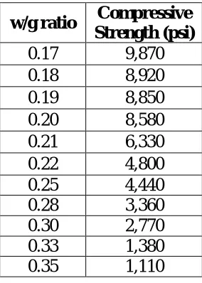
Table 3.1: Effect of w/g ratio in Compressive Strength at 3 day-old
w/g ratio Compressive Strength (psi)
0.17 9,870 0.18 8,920 0.19 8,850 0.20 8,580 0.21 6,330 0.22 4,800 0.25 4,440 0.28 3,360 0.30 2,770 0.33 1,380 0.35 1,110
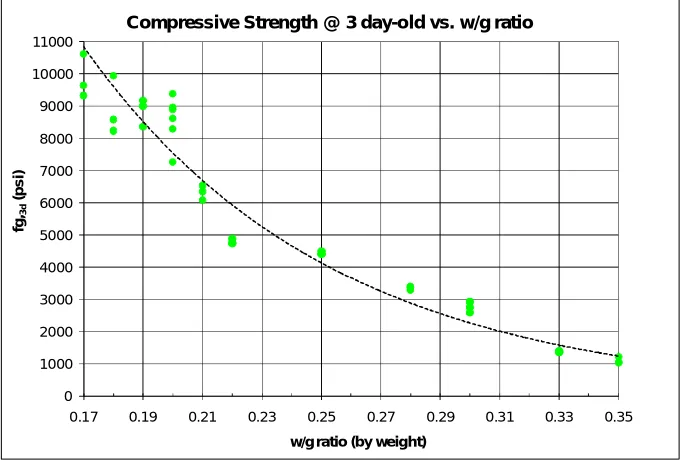
The relationship between the water-to-Grancrete ratio (w/g) by weight to the measured compressive strength at 3 day-old is presented in Figure 3.1.
The observed trend follows the trend known for traditional Portland cement where the compressive strength decreases by increasing the w/g ratio. Analysis of test results suggests that the Compressive Strength can be related reasonably well to the w/g ratio in an
fg,3d = 84,000 e-12(w/g) (r2 = 0.958)
Where:
fg,3d = Compressive Strength at 3 day-old in (psi)
w/g= water-to-Grancrete ratio by weight
Figure 3.1: Effect of w/g ratio on Compressive Strength at 3 day-old
3.5
Effect of water-to-Grancrete ratio on workability
Workability of the fresh Grancrete HFR paste influenced by the water-to-Grancrete (w/g) ratio was evaluated according to the standard ASTM C 1437 (Flow of Hydraulic Cement Mortar).
0 1000 2000 3000 4000 5000 6000 7000 8000 9000 10000 11000
0.17 0.19 0.21 0.23 0.25 0.27 0.29 0.31 0.33 0.35
fg,
3d
(p
s
i)
w/g ratio (by weight)
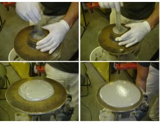
For this purpose, a frustum of a cone specimen mold was filled up using two layers of paste. Then, the mold was removed and using a the flow table shown in Figure 3.2, the specimen was subjected to 25 drops of one inch each in a period of 15 seconds. Four measures of the base diameter of the mortar along scribed lines in the table top were taken using a caliper and these values were averaged and compared with the original base diameter. The method calculates the increase in the average base diameter of the paste mass, expressed as a percentage of the original base diameter. Figure 3.3 illustrates the test procedure and the change in the base diameter of the paste.
Figure 3.3: Flow Test
Test results of the flow test are given in Table 3.2 for different water-to-Grancrete ratios ranging from 0.16 to 0.25 by weight. As expected, the higher the w/g ratio, the higher the flow.
Table 3.2: Effect of w/g ratio on Flowability of Fresh Grancrete HFR paste
w/g ratio Flow (%) Remarks
0.16 - Too dry mixture 0.17 21 Very Low flow 0.18 88 Low Flow 0.19 88 Low Flow 0.20 101 Good Flow 0.21 124 Good Flow 0.22 119 Good Flow 0.23 136 High Flow 0.24 148 Very High Flow
Using the characterization of flow according to the recommendation of standard ASTM C 109, which states in section 3.1 that “Water content for other cements is that sufficient to obtain a flow of 110 ±5 in 25 drops of the flow table”, a minimum w/g ratio of 0.20 is required to achieve sufficient flow.
Test results indicate that the workability of the fresh Grancrete HFR paste, measured by the flow, is highly sensitive and directly proportional to the w/g ratio used. The following polynomial relationship seems to fit reasonable well for the flow data obtained:
F = -16,880(w/g)2 + 8,440(w/g) – 910, (r2=0.906) Where:
F= Flow (%)
w/g= water-to-Grancrete ratio by weight
0 15 30 45 60 75 90 105 120 135 150 165 0 1000 2000 3000 4000 5000 6000 7000 8000 9000 10000 11000
0.17 0.18 0.19 0.2 0.21 0.22 0.23 0.24 0.25 0.26 0.27
F lo w (%) fg ,3d (p s i)
w/g ratio (by weight)
Compressive Strength @ 3 days old and Flow vs. w/g ratio
Compressive Stregth Flow Expon. (Com pressive Stregth) Poly. (Flow)
Figure 3.4 Effect of w/g ratio on Compressive Strength and Flow of Grancrete HFR
It can be observed that a small change of the w/g ratio can produce a significant change in the compressive strength. For example, as we said earlier, a minimum w/g ratio of 0.20 is
a good quality control program should be applied when using Grancrete HFR to avoid variations in the specified w/g ratio.
3.6
Selection of potential mixtures for construction applications
Based on the results obtained during preliminary work, that is compressive strength tested at 3 day-old and flowability of the fresh Grancrete HFR paste, two mixtures that could
represent the limits of the water-to-Grancrete (w/g) ratio in which Grancrete HFR is expected to be used for typical construction applications were selected for further testing:
• Mixture # 1: Grancrete HFR paste with w/g ratio equal to 0.20, which give an average compressive strength of 8,580 psi after 3 days of curing, and Flow equal to 101%.
3.7
Microscopic and Chemical Analysis
Microscopic and chemical analyses of Grancrete HFR were performed by the Analytical Instrumentation Facility at North Carolina State University. The objective of this study was to characterize Grancrete HFR paste and powder and compare the results to the analysis of Portland cement paste. This characterization included elemental composition and initial understanding of the microstructure.
In order to accomplish this objective, samples were prepared at the Constructed Facilities Laboratory at NCSU and analyzed by the Analytical Instrumentation Facility. This analysis was extremely useful to a better understanding of the product at the initial phase of this research. EDX (Energy Dispersive Analysis using X-rays) was used to study the elemental composition of Grancrete HFR.
Scanning Electron Microscopy images were obtained using a Hitachi S-3200 at 20 and 30 kV electron beam with an Oxford Isis EDX system for elemental analysis. Because the high energy electron beam can be focused to obtain lateral resolution on the order of 5nm, it is possible to obtain EDX elemental information from small regions. Specimens used for EDX analysis were not sputtered.
*Source: Analytical Instrumentation Facility, NCSU
Figure 3.5: EDX of Grancrete HFR paste (I)
Figure 3.5 shows and EDX of the many small round features found in the specimen of Grancrete HFR. EDX analysis indicates that they are mostly Silicon (Si), Aluminum (Al), Potassium (K), Calcium (Ca), Oxygen (O) and Magnesium (Mg). This is an indication that these particles are likely to be a type of glass. These clear particles were also observed in the optical microscope.
*Source: Analytical Instrumentation Facility, NCSU
Figure 3.6: EDX of Grancrete HFR paste (II)
*Source: Analytical Instrumentation Facility, NCSU
Figure 3.7 presents and EDX of some large irregular features. Analysis shows high Silicon (Si) and Oxygen (O) indicating that they are probably quartz.
Figure 3.8 shows an EDX of some long crystals in the surface. Analysis shows high Silicon (Si), Calcium (Ca) and Oxygen (O) with some Potassium (K) and Magnesium (Mg).
*Source: Analytical Instrumentation Facility, NCSU
Figure 3.8: EDX of Grancrete HFR paste (IV)
In conclusion, the elemental composition of Grancrete HFR significantly differs from the elemental composition of traditional Portland cement as it can be seen in Figure 3.9 and Figure 3.10, respectively.
*Source: Analytical Instrumentation Facility, NCSU
Figure 3.9: Grancrete HFR paste EDX Spectra
*Source: Analytical Instrumentation Facility, NCSU
Other scanning electron micrographs obtained are shown in Figures 3.11 and 3.12.
Figure 3.11: Scanning Electron Micrograph of Grancrete HFR paste (Mag. 2500X)
Figure 3.11 shows a SEM micrograph of Grancrete HFR surface taken after 3 days of air curing. High magnification (2500 X) shows that there are many small crystallites on the surface of the sample. The EDS spectra of this region showed the same background as the overall EDS spectra.
Figure 3.12 presents a SEM micrograph of Grancrete HFR surface after 3 months of air curing with a magnification of 180 X. Note that features of about 100 to 200 µm in length and varying width can be seen in this cleaved surface. The Grancrete HFR is not
CHAPTER 4
4
PROPERTIES OF THE FRESH MIXTURE OF
GRANCRETE HFR
4.1
Introduction
This Chapter describes the experimental program undertaken at the Constructed Facilities Laboratory at North Carolina State University to study the properties of the fresh mixture of Grancrete HFR paste. The experimental program includes the two mixtures selected
previously from the preliminary work. Setting time, temperature and pH were investigated as a function of time. Information about experimental program, testing apparatus and
procedures as well as analysis of the measured data of each characteristic investigated is reported in this chapter.
4.2
Setting Time
4.2.1 Experimental Program
Setting time was determined according to standard ASTM C 403 (Time of Setting of
Concrete Mixtures by Penetration Resistance). The resistance of the sample to penetration by standard needles was measured and from the relationship of penetration resistance with elapsed time, the times of initial and final setting were determined.
This test method in particular defines initial setting time as the time at which the mixture has a penetration resistance equal to 500 psi, while final setting time is defined as the time at which the mixture has a penetration resistance equal to 4,000 psi.
Three 8-inch diameter and 6-inch height cylindrical specimens were tested for each of the selected mixtures as given in Table 4.1. Each specimen was prepared in a single batch according to the procedure described in section 3.3.2.
Table 4.1: Setting Time Test Matrix
Mixture ID w/g (by weight) No. of Specimens
Mixture #1: Grancrete HFR Paste 0.20 3 Mixture #2: Grancrete HFR Paste 0.25 3
4.2.2 Test Apparatus and Procedure
resistance was calculated as given in Table 4.2. Table 4.2 provides detailed information with regards of the measured needle’s diameter, the corresponding area, and the forces required to reach the specified penetration resistances of 500 and 4000 psi.
Table 4.2: Forces required to reach Initial and Final setting times by needle
Needle
Number Diameter (in) Area (in
2
) Force to reach Force to reach 500 psi (Lb) 4000 psi (Lb)
1 1.1170 0.98 490 3920
2 0.7905 0.49 245 1963
3 0.5500 0.24 119 950
4 0.3420 0.09 46 367
5 0.2390 0.04 22 179
6 0.1645 0.02 11 85
Each cylindrical specimen was casted using a plastic mold filled up in a single layer of Grancrete HFR paste. These were consolidated to eliminate air pockets by 50 rod strokes (1 rod for each 1 in2) uniformly distributed over the cross section of the specimen and the sides were hand tapped in order to close the voids left by the tamping rod and also to level the surface of the specimen.
Figure 4.1: Test of Setting Time by Penetration Resistance
4.2.3 Test Data and Analysis
The measured forces required to produce the 1-in penetration was divided by the
corresponding needle’s area and thus obtaining penetration resistance values. These values were plotted versus the corresponding elapsed time. Then, by linear interpolation, initial and final setting times were obtained from each plot as the times when the penetration resistance equals 500 psi and 4000 psi, respectively. Figure 4.2 presents a plot of penetration resistance versus elapsed time for the three specimens tested for Mixture #1 with w/g of 0.20.
Loading Apparatus
Mixer
0 1,000 2,000 3,000 4,000 5,000 6,000 7,000 8,000 9,000 10,000
6 7 8 9 10 11
P e n e tr a ti o n R es is ta n ce ( p s i) Time (min)
Setting Time by Penetration Resistance Mixture #1 (w/g=0.20)
Initial Setting
Final Setting Specimen 1
Specimen 2
Specimen 3
Figure 4.2: Setting Time by Penetration Resistance, Mixture #1
The initial and final setting times for the three specimens tested as well as the average value for Mixture #1 are given in Table 4.3. The table shows also the time difference between final and initial setting in seconds.
Table 4.3: Setting Time by Penetration Resistance, Mixture # 1 (w/g=0.20)
Specimen Initial Setting (minutes)
Final Setting (minutes)
∆t (seconds) (Final Set. -Initial Set.)
1 7.90 8.29 23
2 8.69 9.40 43
3 9.04 9.66 37
0 1,000 2,000 3,000 4,000 5,000 6,000 7,000 8,000 9,000 10,000
8 9 10 11 12 13
P e n e tr a ti o n R e s is ta n ce ( p s i) Time (min)
Setting Time by Penetration Resistance Mixture #2 (w/g=0.25)
Initial Setting
Final Setting Specimen 3
Specimen 1
Specimen 2
The same information is presented in Figure 4.3 and Table 4.4 for Mixture #2 with w/g ratio of 0.25 by weight.
Figure 4.3: Setting Time by Penetration Resistance, Mixture #2
Table 4.4: Setting Time by Penetration Resistance, Mixture #2 (w/g=0.25)
Specimen Initial Setting (minutes)
Final Setting (minutes)
∆t (seconds) (Final Set. -Initial Set.)
1 9.57 10.59 61
2 9.70 11.02 79
3 9.75 10.48 44
Average 9.67 10.70 61
Rounding and reporting to the nearest 0.5 minutes, test results of setting time by penetration resistance indicate that the initial setting time for Mixture # 1 with w/g ratio of 0.20 was 8.5 minutes and the final setting time was 9 minutes. While for Mixture # 2 with w/g ratio of 0.25, initial setting time was 9.5 minutes and final setting time was 10.5 minutes. These values are significantly lower than the typical values reported for the setting time of conventional Portland cement. According to the literature, Portland cement has an initial setting time between 1.5 - 3 hours and a final setting time between 4 - 6 hours.
4.3
Temperature Monitoring
Grancrete HFR mixed with water is known to produce an exothermic reaction. The purpose of the investigation presented in this section is to monitor the temperatures developed in Grancrete HFR paste samples in order to determine the maximum temperatures reached and the corresponding times when they occur. This section describes the experimental program, test apparatus and procedures used as well as analysis of the measured data.
4.3.1 Experimental Program
Table 4.5: Temperature Monitoring Test Matrix
Mixture ID w/g
(by weight) Location
4” by 8” cylinders
2-in cubes
Mixture #1:
Grancrete HFR Paste 0.20
Air 2 2
Insulated - 2
Mixture #2:
Grancrete HFR Paste 0.25 Air 2 -
4.3.2 Test Apparatus and Procedure
Temperature of the Grancrete HFR paste was monitored using thermocouples embedded in the middle of two types of specimens: 4” by 8” cylinders and 2-in cubes. Each specimen was monitored for a period of 24 hours using a data acquisition system connected to the
embedded thermocouples. Ambient temperature at 5 feet-height from the floor was also monitored on each testing day. Data points were recorded at a rate of 1 point every 5 minutes.
Cube specimens were prepared according to standard ASTM C 109 (Compressive Strength of Hydraulic Cement Mortars). In this case specimens were only prepared from Mixture #1 with w/g ratio of 0.20. Six specimens were prepared using two sets of plastic molds. Each mold had space for 3 specimens in a single row. Molds were filled up using two equal layers. Each layer was consolidated using the hand tamping procedure described on ASTM C 109. Even though 6 specimens were prepared, only 4 specimens were used in temperature monitoring test. Temperature of the specimens located in the middle of the mold was not monitored. Molds were not striped. One set of molds with two embedded-cubes was in direct contact with the ambient (air), while the other set of thermocouple-embedded-cubes was inside of an insulated box as shown in Figure 4.4.
Insulating
Box
Insulated Specimens
60 70 80 90 100 110 120 130 140 150 160
0 1 2 3 4 5 6 7 8 9 10 11 12 13 14 15 16 17 18 19 20 21 22 23 24
T e m p e ra tu re ( °F) Time (Hours)
Temperature vs Time
Using 4" by 8" cylinders Mixture # 1 (w/g=0.20)
Specimen 1
Specimen 2
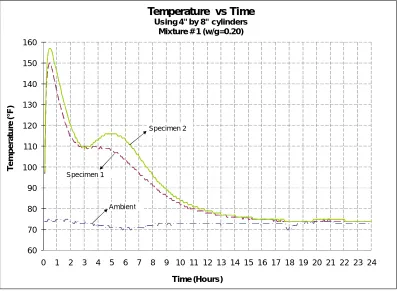
Ambien t 4.3.3 Test Data and Analysis
Data of temperature versus elapsed time was plotted for every single specimen monitored. Elapsed time was measured after initial contact of Grancrete HFR and water. Figure 4.5 presents values of temperatures versus elapsed time recorded for the cylindrical specimens used for Mixture #1. The maximum temperature recorded was 157 °F at approximately 30 minutes. The ambient temperature at a distance of 5 feet from the floor reported values ranging from 70 to 75 °F. Note that specimens reached equilibrium with the ambient temperature after approximately 20 hours.
60 70 80 90 100 110 120 130 140 150 160
0 1 2 3 4 5 6 7 8 9 10 11 12 13 14 15 16 17 18 19 20 21 22 23 24
T e m p e ra tu re ( °F) Time (Hours)
Temperature vs. Time
Using 4" by 8" cylinders Mixture # 2 (w/g=0.25)
Specimen 1
Specimen 2
Ambient
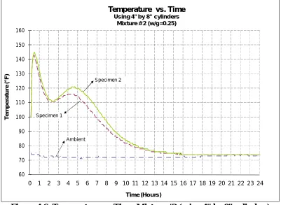
Figure 4.6 presents values of temperatures versus elapsed time recorded for the cylindrical specimens used for Mixture #2. In this case, the maximum measured temperature was 145 °F at approximately 30 minutes. The ambient temperature at a distance of 5 feet from the floor reported values ranging from 71 to 75 °F. Note that specimens also reached the equilibrium with the ambient temperature after approximately 20 hours.
Figure 4.6: Temperature vs. Time, Mixture #2 (using 4” by 8” cylinders)
60 70 80 90 100 110 120 130 140 150 160
0 1 2 3 4 5 6 7 8 9 10 11 12 13 14 15 16 17 18 19 20 21 22 23 24
T e m p e ra tu re ( °F) Time (Hours)
Temperature vs. Time
Using 4" by 8" Cylinders
Avg. w/g=0.20
Avg. w/g=0.25 Mixture#1 (w/g=0.20)
Mixture#2 (w/g=0.25)
generated. A difference of 10 °F can be observed between Mixture #1 and Mixture #2; however, the maximum temperatures occurred at approximately 30 minutes for both
mixtures. Note that curves of temperature versus elapsed time obtained present two peaks, at this time it is not clear why that happened but it may be due to a secondary reaction. Future research may be considered to address this phenomenon.
Figure 4.7: Temperature vs. Time (using 4” by 8” cylinders)
60 70 80 90 100 110 120 130 140
0 1 2 3 4 5 6 7 8 9 10 11 12 13 14 15 16 17 18 19 20 21 22 23 24
T e m p e ra tu re ( °F) Time (Hours)
Temperature vs Time
Using 2-in cubes Mixture #1 (w/g=0.20)
Insulated Specimen 1
Insulated Specimen 2
Air Specimen 1
Air Specimen 2
Ambient
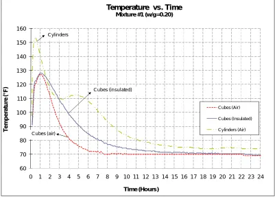
Figure 4.8, for the cubes in direct contact with air, the maximum temperature recorded was 128 °F at approximately 1 hour; while for the insulated cubes the maximum recorded value of temperature was 130°F at 1 hour also. In this case, the ambient temperature at a distance of 5 feet from the floor reported values ranging from 63 to 71 °F.
Figure 4.8: Temperature vs. Time, Mixture #1 (using 2-in cubes)