ABSTRACT
RAGAN, DAVID MICHAEL. Behavior of Efficient Two Story Precast Concrete Wall Panels. (Under the direction of Dr. Sami Rizkalla)
Precast concrete panels are utilized by engineers in order to create an efficient
structural system. These panels can be used in the design of high rise buildings, residential
units, and commercial structures. Market demand requires a time and cost efficient system,
but at the same time, this system can not compromise the structural integrity of the system.
Precast concrete panels provide several advantages including fabrication and product quality
control, a significant reduction in construction and manufacturing time, fire resistance,
durability, architectural variability, thermal and acoustical efficiency, and most importantly a
savings in cost. There are several types of precast concrete wall panels including solid
panels, insulated panels, sculptured panels, hollow core panels, and ribbed panels. The
ribbed panels are comprised of a certain number of structural ribs connected by a thin
concrete slab or skin. These panels can be reinforced with rebar, welded wire mesh, or a
fiber reinforcing material. A research program was conducted at the Constructed Facilities
Laboratory at North Carolina State University in order to investigate the behavior of two
story precast concrete ribbed wall panels. An experimental investigation was conducted on
two full-scale panels in order to find a failure mechanism. A finite element model was then
created in order to predict panel behavior and analyze performance. This model was then
Behavior of Efficient Two Story Precast Concrete Wall Panels
by
David Michael Ragan
A thesis submitted to the Graduate Faculty of North Carolina State University
in partial fulfillment of the requirements for the degree of
Master of Science
Civil Engineering
Raleigh, North Carolina
2011
APPROVED BY:
_____________________________ ____________________________ Dr. Vernon Matzen Dr. Rudolf Seracino
________________________________ Dr. Sami Rizkalla
ii
BIOGRAPHY
David Michael Ragan was born September 6th, 1987 in Raleigh, NC. He spent his
entire childhood and adolescence in Cary, North Carolina. After graduating from high
school he decided to attend North Carolina State University in order to pursue an
undergraduate degree in Civil Engineering. After graduating, he decided to continue his
education at North Carolina State University in order to receive a Master‟s of Science in
Structural Engineering and Mechanics. He intends to become a professional engineer with a
iii
ACKNOWLEDGEMENTS
I would first like to acknowledge my advisor and committee chair, Dr. Sami Rizkalla
for his guidance throughout my entire research and graduate school career. His role as a
mentor as well as his dedication to me, have not only given me the ability to progress as a
student but also as an engineer. I would also like to thank the rest of my committee, Dr.
Vernon Matzen and Dr. Rudolf Seracino. Dr. Matzen has had a large influence on both my
undergraduate and graduate career playing a part in my development as a professional. Dr.
Seracino has always been available to offer any advice that I may need or answer any
questions that I may have.
I would like to express my gratitude to the corporate sponsors of the project for
providing financial as well as material assistance for the project.
I would like to recognize all the CFL graduate students who made the working
environment not only professional but enjoyable. I would particularly like to recognize those
who have worked with me not only from the beginning of my graduate career, but also my
undergraduate career, Tyler Storm, Kurtis Kennedy, and Chad Goodnight. Their help and
assistance, as well as everyone else‟s, has helped make everything possible.
I would also like to thank the CFL professional staff, Greg Lucier, Jerry Atkinson,
and Jonathon McEntire, as well as the undergraduate assistants who helped me during the
testing in the laboratory. Also, Denise Thoesen, Brianne Ryen, Diana Lotito, Toni Pascucci,
iv process.
Finally, I would like to thank my family and friends for their past, present, and future
v
TABLE OF CONTENTS
List of Tables ... ix
List of Figures ... x
1 Introduction ... 1
1.1 Background ... 1
1.2 Objective ... 2
1.3 Scope ... 3
2 Literature Review ... 5
2.1 Introduction ... 5
2.2 Background and Development ... 5
2.3 Advantages of Precast Wall Panels ... 7
2.4 Design Features ... 10
2.5 Structural Behavior ... 12
2.6 Special Code Provisions ... 19
3 Experimental Investigation ... 23
3.1 Introduction ... 23
3.2 Overview ... 23
vi
3.4 Test Setup ... 26
3.5 Details of Test Setup ... 29
3.5.1 Support Conditions ... 31
3.5.2 Loading Sequence ... 33
3.5.2.1 Fatigue Cycles ... 35
3.5.3 Instrumentation ... 40
3.5.3.1 Load Cells ... 40
3.5.3.2 String Potentiometers ... 41
3.5.3.3 Pi Gages ... 43
3.6 Test Results ... 45
3.6.1 Summary of Test Results ... 45
3.6.2 Panel RWP1: Test 1 Results ... 46
3.6.2.1 Deflection: Service Load Level ... 46
3.6.2.2 Strain: Service Load Level ... 48
3.6.2.3 Cracking Pattern: Service Load Level ... 51
3.6.2.4 Failure Mode... 52
3.6.2.5 Deflection: Failure Load Level... 53
3.6.2.6 Strain: Failure Load Level ... 55
vii
3.6.4 Panel RWP1: Retest Results ... 60
3.6.4.1 Deflection: Maximum Load Level ... 61
3.6.4.2 Strain: Maximum Load Level... 63
3.6.4.3 Cracking Pattern: Maximum Load Level ... 66
3.6.5 Panel RWP2: Test 1 ... 68
3.6.6 Panel RWP2: Test 1 Results ... 71
3.6.6.1 Deflection: Maximum Load Level ... 71
3.6.6.2 Strain: Maximum Load Level... 73
3.6.6.3 Cracking Pattern: Maximum Load Level ... 76
3.6.7 Panel RWP2: Retest (No Gravity Loads) ... 78
3.6.8 Panel RWP2: Retest Results ... 78
3.6.8.1 Deflection: Maximum Load Level ... 78
3.6.8.2 Strain: Maximum Load Level... 80
3.6.9 Effects of Gravity Loads ... 82
3.7 Experimental Summary and Conclusions ... 85
4 Analytical Investigation ... 88
4.1 Introduction ... 88
4.2 Overview ... 88
viii
4.4 Phase II: Finite Element Model ... 92
4.5 Phase III: Calibration of the Finite Element Model ... 95
4.6 Phase IV: Parametric Study... 103
4.6.1 Effect of Applied Uniform Pressure Load vs. Concentrated Load ... 105
4.6.2 Use of Only Two Interior Ribs ... 109
4.6.3 Use of Only One Interior Rib ... 112
4.6.4 Reducing the Width of the Exterior Ribs ... 117
4.6.5 Two Story Clear Height Panels... 120
4.7 Summary and Conclusions ... 124
5 Observations, Conclusions, Recommendations ... 127
5.1 Summary of Research ... 127
5.2 Observations ... 127
5.3 Conclusions ... 128
5.4 Recommendations for Future Work ... 130
6 References ... 131
Appendix ... 134
ix
LIST OF TABLES
Table 3-1 – Applied Loading Sequence... 35
Table 3-2 – Rayleigh Probability of Exposure at Certain Wind Speeds ... 39
Table 3-3 – Summary of Ultimate Loads for Panels RWP1 and RWP2 ... 46
Table 3-4 – Strain vs. Gravity Load, No Lateral Load ... 85
Table 4-1 – Frame Analysis: Critical Deflections ... 90
Table 4-2 – Finite Element Analysis: Critical Deflections ... 95
Table 4-3 – Comparison of Results: Frame Analysis and FEA ... 95
Table 4-4 – Critical Deflections: FEA and Experimental Results ... 99
Table 4-5 – Critical Strains: FEA and Experimental Results ... 102
Table 4-6 – Critical Deflections: Uniform Pressure Load ... 106
Table 4-7 – Critical Strains: Uniform Pressure Load ... 107
Table 4-8 – Critical Deflections: Two Interior Ribs ... 111
Table 4-9 – Critical Strains: Two Interior Ribs ... 111
Table 4-10 – Critical Deflections: One Interior Rib ... 114
Table 4-11 – Critical Strains: One Interior Rib ... 115
Table 4-12 – Critical Deflections: Thin Exterior Ribs... 119
Table 4-13 – Critical Strains: Thin Exterior Ribs ... 119
Table 4-14 – Critical Deflections: No Middle Support ... 121
x
LIST OF FIGURES
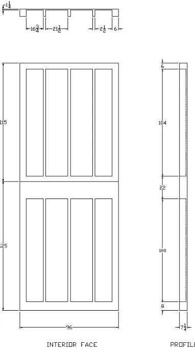
Figure 3.1 – General Dimensions of a Two-Story Precast Concrete Ribbed
Wall Panel ... 25
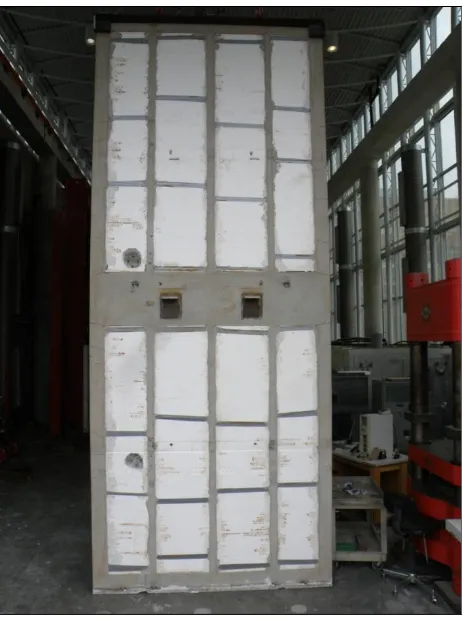
Figure 3.2 – Typical Two-Story Precast Concrete Ribbed Wall Panel ... 26
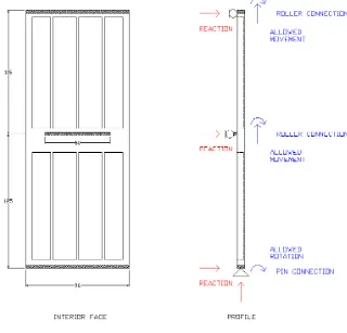
Figure 3.3 – Schematic View of Constraint Locations ... 27
Figure 3.4 – Schematic View of Load Locations (Dimensions shown are in inches) ... 28
Figure 3.5 – Conceptual Test Setup ... 30
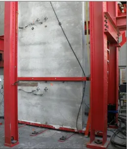
Figure 3.6 – Exterior and Interior View of Completed Test Setup ... 31
Figure 3.7 – Base Connections ... 32
Figure 3.8 – Overview (left) and Close-View (right) of Mid-Height Connections ... 32
Figure 3.9 – Overview (left) and Close-View (right) of Top Connections ... 33
Figure 3.10 – Probability Distribution and Density Functions ... 38
Figure 3.11 – Load Cell ... 41
Figure 3.12 – String Pot Locations ... 42
Figure 3.13 – String Pot Setup ... 43
Figure 3.14 – Pi Gage Locations... 44
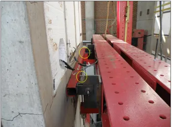
Figure 3.15 – Overview (left) and Close-View (right) of Selected Orthogonal PI-Gages ... 45
xi
Service Load ... 47
Figure 3.17 – Deflection (SP-4) vs. Lateral Load, 50-year Design Life and Service Load ... 48
Figure 3.18 – Strain (PI-2V) vs. Lateral Load, 50-year Design Life and Service Load ... 50
Figure 3.19 – Strain (PI-8V) vs. Lateral Load, 50-year Design Life and Service Load ... 51
Figure 3.20 – Specimen RWP1 after Sustaining +/- Service Load: No Cracks ... 52
Figure 3.21 – Overview (left) and Close-view (right) of Panel RWP1 Failure Mode ... 53
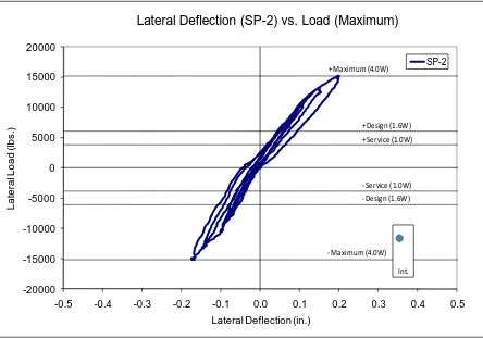
Figure 3.22 – Deflection (SP-2) vs. Lateral Load, 50-year Design Life and Failure ... 54
Figure 3.23 – Deflection (SP-4) vs. Lateral Load, 50-year Design Life and Failure ... 55
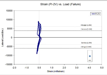
Figure 3.24 – Strain (PI-2V) vs. Lateral Load, 50-year Design Life and Failure ... 57
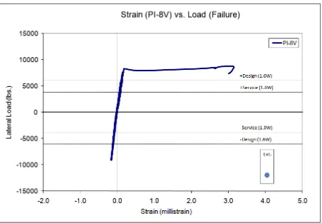
Figure 3.25 – Strain (PI-8V) vs. Lateral Load, 50-year Design Life and Failure ... 58
Figure 3.26 – Specimen RWP1 with Strengthened Mid-Height Connection ... 59
Figure 3.27 – Specimen RWP1 at Conclusion of Test (After Sustaining +/- 4.0W) ... 60
Figure 3.28 – Deflection (SP-2) vs. Lateral Load, Maximum Load Cycles ... 62
Figure 3.29 – Deflection (SP-4) vs. Lateral Load, Maximum Load Cycles ... 63
xii Figure 3.31 – Strain (PI-8V), Maximum Load Cycles ... 66
Figure 3.32 – Interior Panel Cracking: Specimen RWP1 after all Tests
(Surface cracks located on edges of panel across full height,
cracks digitally highlighted) ... 67
Figure 3.33 – Exterior Panel Cracking: Specimen RWP1 after all Tests (Most
Cracks located at base quarter-height, all horizontal, cracks
digitally highlighted) ... 68
Figure 3.34 – Specimen RWP2 after Sustaining +/- Service Load: No Cracks ... 69
Figure 3.35 – Specimen RWP2 at Conclusion of Test (After Sustaining +/-
4.0W) ... 70
Figure 3.36 – Deflection (SP-2) vs. Lateral Load, Maximum Load Cycles ... 72
Figure 3.37 – Deflection (SP-4) vs. Lateral Load, Maximum Level Cycles ... 73
Figure 3.38 – Strain (PI-2V) vs. Lateral Load, 50-year Design Life and
Maximum Load ... 75
Figure 3.39 – Strain (PI-8V) vs. Lateral Load, 50-year Design Life and
Maximum Load ... 76
Figure 3.40 – Interior Panel Cracking: Specimen RWP2 after all Tests
(Surface cracks located on edges of panel across full height,
cracks digitally highlighted) ... 77
Figure 3.41 – Exterior Panel Cracking: Specimen RWP2 after all Tests
(Cracking around the lower lateral load point, cracks digitally
xiii Figure 3.42 – Deflection (SP-2) vs. Lateral Load, Maximum Load (No
Gravity Load) ... 79
Figure 3.43 – Deflection (SP-4) vs. Lateral Load, Maximum Load (No Gravity Load) ... 80
Figure 3.44 – Strain (PI-2V) vs. Lateral Load, Maximum Load (No Gravity Load) ... 81
Figure 3.45 – Strain (PI-4V) vs. Lateral Load, Maximum Load (No Gravity Load) ... 82
Figure 3.46 – Lateral Deflection vs. Gravity Load, No Lateral Load ... 84
Figure 4.1 – Frame Analysis: Deflections ... 91
Figure 4.2 – Finite Element Analysis: Solid Model ... 93
Figure 4.3 – Finite Element Analysis: Meshed Solid Model ... 94
Figure 4.4 – Finite Element Analysis: Experimental Panel ... 97
Figure 4.5 – Deflections: FEA ... 98
Figure 4.6 – Comparison of Critical Deflections: FEA and Experimental Results ... 99
Figure 4.7 – Strain: FEA ... 102
Figure 4.8 – Comparison of Critical Deflections: Uniform Loading... 106
Figure 4.9 – Strain: Uniform Pressure Load ... 108
Figure 4.10 – Finite Element Analysis: Two Interior Ribs ... 110
Figure 4.11 – Finite Element Analysis: One Interior Rib ... 113
xiv
Figure 4.13 – Strain: One Interior Rib ... 116
Figure 4.14 – Finite Element Analysis: Thin Exterior Ribs ... 118
Figure 4.15 – Deflection: No Middle Support ... 121
Figure 4.16 – Strain: No Middle Support ... 123
1
1
INTRODUCTION
1.1 Background
Precast reinforced concrete wall panels are typically used for creating the building
envelope of industrial and commercial structures as well as the structural frame of these
buildings. Structural panels are designed to support gravity loads, including the dead and
live loads from roof and floor systems, as well as lateral loads, due to wind. Such panels can
thus be utilized in the design of buildings, residential units, and commercial structures.
Market demand for these types of panels requires that the panels be cost efficient and
detailed for simple erection methods in order to reduce construction time. These panels
should also be structurally designed to satisfy all code provisions. Precast concrete wall
panels have proven records to meet such demands.
Precast reinforced concrete wall panels can be configured to produce strong, durable
structures which are cost-effective, sustainable, provide for thermal efficiency, and highly
capable of resisting natural hazard environments. They also have excellent quality control,
fire resistance, allowances in architectural variability, and a significant reduction in
fabrication and construction time. Several types of panels have been developed including
solid panels, hollow-core panels, insulated panels, sculptured panels, tee section panels, and
ribbed panels. Each panel is designed in order to create the most efficient system for the
specified application.
2 well as the thermal efficiency. Also, research is necessary to investigate the performance and
behavior of any new panel system. The research typically focuses on ways to optimize the
panel‟s structural configuration and design. This optimization strives to increase overall
efficiency and savings with respect to the use of material.
This research focuses on a new proposed two-story precast concrete ribbed wall
panel. This panel is intended to be used for residential and commercial applications, and
utilizes randomly oriented synthetic fibers mixed in the concrete known as fiber reinforced
concrete (FRC), to control cracking of the exterior face. The ultimate goal of the panel is to
provide a structurally and thermally efficient system with savings in cost of construction and
material. Ribs are used to allow for the inclusion of rigid foam insulation to increase the
thermal efficiency of the panel.
1.2 Objective
The main objective of this research is to evaluate the structural behavior and failure
modes of the proposed two story precast concrete ribbed wall panels, under the effect of a
loading equivalent to a 50-year design life. The second objective is to develop an analytical
model to predict structural behavior and use the experimental results to calibrate the
analytical model. The third objective is to use the calibrated model to optimize the panel
3
1.3 Scope
The scope of this project consisted of three phases. The first phase consisted of an
extensive literature review with regards to precast reinforced concrete panels. The second
phase included an experimental program testing two full scale panels. The third phase
involved the formulation of an analytical model based on finite elements utilizing the
experimental results to calibrate the model. The analytical model was used to optimize the
design of the proposed panel.
The literature review, in Chapter 2, consisted of two main parts. The first part
intended to highlight the efficiency of precast concrete panel systems. This part of the
review also describes benefits and ways to optimize panel design. The second part of the
review intended to discuss and describe relevant research and analysis that has been
completed with regards to precast concrete panels.
The experimental program, in Chapter 3, describes the experimental program
conducted on two full scale two-story precast concrete ribbed wall panels under the effect of
gravity and equivalent wind loads. The testing was conducted at the Constructed Facilities
Laboratory at North Carolina State University, within the Department of Civil, Construction,
and Environmental Engineering. Panels were tested vertically in a frame which allowed for
the application of combined gravity and lateral loads. Load and support conditions were
applied in order to simulate typical design and field assumptions. Critical deflections and
strains were measured during the entire experimental program. The panel was first subjected
4 investigate failure mechanisms. All lateral load sequences were performed with the inclusion
of the gravity loads. The behavior of the panel was evaluated during fatigue loading, at
service and design loads, at failure loads, and finally at the maximum allowable load within
the test setup constraints.
Chapter four describes the modeling techniques used to optimize the panel
configuration. A frame analysis is first completed and then compared with a finite element
model analysis. The results from this analysis were used to justify a 3-D solid finite element
model of the panel. The solid finite element model was calibrated using results from the
frame analysis and the measured values from the experiment. The calibrated model was used
in conducting a parametric study on the proposed precast panel. The parameters changed in
panel configuration included fewer interior ribs, thinner exterior ribs, and the exclusion of the
middle support in order to evaluate a full two story height panel.
Chapter five summarizes the research project, and provides conclusions and
recommendations based on the research findings.
Specimen details and dimensions, additional experimental results, and supplemental
5
2
LITERATURE REVIEW
2.1 Introduction
This chapter is a general overview of precast reinforced concrete wall panels. The
sections within this chapter include Background and Development, Advantages of Precast
Wall Panels, Design Features, Structural Behavior, and Special Code Provisions. The
Background and Development section provides a brief description of precast concrete and its
application to wall panels. The Advantages section showcases the benefits of these panels
and the Design Features section describes the necessary design considerations. The
Structural Behavior section covers relevant academic study on the topic. Finally, the Special
Code Provisions section describes special design features found in the applicable codes and
how they are used in the design and analysis process. It should be noted that precast
reinforced concrete wall panels are briefly summarized in order to coincide with the relevant
literature being referenced. The term may be quoted as „precast panel‟ or „concrete panel‟.
2.2 Background and Development
Precast concrete is an efficient means for structural design of commercial, residential,
and special industry buildings. Research and development has enabled a progressive trend
towards the use of precast concrete. Different precast design techniques are being applied in
6 Precast reinforced concrete presents many advantages. These structural elements
provide an efficient and effective method of construction while also providing a practical and
simplified tool for designers. Precast reinforced concrete, as described by PCI, allows for
faster construction speed, quality control during fabrication, fire resistance, durability,
architectural variability, thermal and acoustical control, and an ability to be constructed in all
forms of weather (PCI Design Handbook 6th Edition). Some of these benefits however are a
direct function of some certain practicing philosophies. These philosophies, as described by
PCI, include the use of repetitive designs, economical layouts, and combining structural
features within a precast member (PCI Design Handbook 6th Edition).
Precast concrete can be applied to many structural elements such as wall panels.
These panels can be used in a variety of applications such as high rise buildings, parking
decks, residential units, and commercial structures. All the prior advantages listed by the
PCI Design Handbook can be utilized by these panels in order to make design and
construction more efficient.
Precast panels are generally divided into two categories meant to serve two different
purposes. The first category is exterior cladding. Cladding forms a barrier between interior
space and the weather outside. With respect to structural demands, cladding only transfers
lateral loads to the structural frame. The next category is structural load bearing walls.
These walls allow for more sophisticated structural designs. Structural walls are defined as
walls proportioned to resist combinations of shears, moments, and axial loads (ACI 318-08).
7 these. Therefore a bearing wall can not only resist lateral loads, but also provide structural
support for the gravity loads created by the roof and floor systems as well as other in-plane
loads.
There are many generic and basic styles for designing precast concrete panels. These
include solid panels, hollow-core panels, insulated panels (sandwich), ribbed panels, and
sculptured (architectural) panels (ACI 533R-93).
2.3 Advantages of Precast Wall Panels
There are several advantages specific to using precast reinforced concrete panels in
addition to those listed by the PCI Handbook. These advantages can all lead to a more
efficient structural design which is the ultimate goal in using a precast panel system.
However, designers must take into account multiple considerations in order to realize all the
potential advantages that can be created by using these panels.
Freedman (1999) details the advantages of these panels and their relationship with the
design procedure. The first advantage of using concrete panels is that the structural frame
can be eliminated. This is due to the load bearing capabilities of the panels. The use of the
concrete panels will satisfy structural demands for both lateral and gravity loads, thus
eliminating the need for an exterior frame and typically allowing for a reduction in the size
and scale of the interior frame. The benefits include savings in material and construction cost
8 Another advantage listed by Freedman (1999) is the simplicity of design due to the
repetitive nature of concrete panels. Panels are designed for certain load criteria. Therefore
an efficient panel system will meet all these demands with the use of the same panel. The
benefits include savings in design time, construction time, fabrication time, and overall costs.
Also, precast panels can serve as permanent formwork for cast in place concrete. This will
eliminate the need for temporary formwork as well as the labor, material, and time demands
required to erect it.
The last advantage listed by Freedman (1999) of precast panels is that they can be
used as supplements to other structural systems. They can be combined with cast-in-place
systems, steel framing systems, timber systems, or other precast systems. This gives a
designer more freedom in their approach and allows them to combine the benefits of the
different systems.
The inclusion of thermal control features within a panel in order to meet building
code requirements must be considered. This is typically done by adding an insulating foam
material to the concrete panel. Due to the necessary inclusion of the foam material, different
designs of the panel have been developed in order to effectively incorporate it. For example,
ribbed panels can fill the spaces between ribs with foam material in order to increase the
thermal efficiency.
In order to gain the advantages listed prior and thus provide the benefits generated by
using precast panels, certain fundamental design philosophies must be satisfied. Freedman
9 This sizing requirement will reduce the number of panels needed and reduce the number of
joints and connections. This in turn will create savings in fabrication, transportation, and
erection and make a more efficient system.
Freedman (1999) also states that the way loads are applied within the system will
determine the efficiency of a precast panel system. The ability for the panels to act as shear
walls factors into the ability to eliminate a shear resisting system. Also, the uniform
distribution of loads within a panel is important. This relates to the way that stresses are
created within the panel section due to applied loads and also to the way that loads are
transferred between connections and to foundations.
Finally, the dimensioning, details, and connections will also affect the use of these
precast panels. The dimensioning requirements affect panel sizes, spacing, and the
allowances for openings. Also, the ability for connections to transfer loads between panels
creates an efficient precast wall system.
Koncz (1995) conducted a study on the efficiency of using concrete panel systems in
building construction. The author states that the large panel building system was developed
in France in the 1950‟s and that it has thus been utilized with increasing efficiency in the
structural market. This precast panel system can be applied to high rise structures, residential
units, and commercial construction. Koncz (1995) specifically explains a system referred to
as the all-wall load bearing system which is currently in use in European and Asian countries.
This system connects precast panels in order to create one structural unit as opposed to
10 analysis predicts the development of stresses within the system. The author states that
through experimental work the model is justified in predicting stresses. Thus the author
concludes that large panel systems can be used in order to increase the efficiency of
structural systems as the predicted and experimental stresses developed throughout the
system are acceptable.
Zielinska and Zielinski (1982) completed research on the overall efficiency of using
precast ribbed panel systems. The authors researched the application of the panels to many
structural forms including small residential units and large scale structures. The panels were
ten feet in height with ribs spaced four feet apart and ten inches thick. Welded wire mesh
was used to reinforce a 2.5 inch thick exterior skin. The authors cited several examples
utilizing the panels. One example required 2.5 days to erect the precast framing system.
Also, the overall cost of the structure was comparable with other similar structures. Another
example combined a timber roof with precast panels. The structure showcases the structural
adaptability of precast panels. The authors conclude that precast panel systems are effective
for decreasing costs while increasing overall efficiency.
2.4 Design Features
There are several considerations that need to be made when formulating an approach
to an overall design for precast reinforced concrete wall panels. This section will initially
discuss considerations relative to structural design and then discuss considerations that a
11 The first consideration to be made is the design load cases. Gravity or vertical loads
can create purely axial forces when applied to a member concentrically. These loads can also
be applied eccentrically, creating additional moments that must be considered. Concrete
panels will also be influenced by lateral loads due to wind and seismic forces. Therefore a
designer must consider the panel as a member under both axial and lateral loads. Lastly, the
designer must consider whether or not to treat precast panels as shear walls.
Volume changes created from creep, shrinkage, and temperature variations must also
be considered. A designer should size joints and space them according to the determined
volume changes. Allowable tolerances related to both design demands and also fabrication
and erection standards should be considered.
Connections are another significant design consideration. Typical panel failure
occurs at a connection as opposed to a structural failure. Connections allow for movement,
transfer of forces, and stability. Connections include bolting, welding, grouting, or a
combination of those listed. These connections attach the panel to the foundation, floor
slabs, roofs, and to other panels.
Several design considerations related to construction and architectural aspects of the
concrete panels must also be investigated. These aspects of design are addressed in order to
design the most overall efficient concrete panel. Design of a precast panel can be divided
into many categories including transportation, erection, fabrication, and architectural design.
12 reinforced concrete panel must be considered in order to estimate shipping costs, delivery
truck size and capacity, and shipping distance. Also, the means and methods of construction
are necessary in order to determine equipment required for construction and the speed at
which the panels can be erected as well as site access. Another consideration to be made is
the fabrication process with respect to the ease of replication of a panel, overall amount of
material used, and the complexity of the panel fabrication. Finally, architectural
considerations must be made. This relates to ventilation, thermal properties, overall
dimensioning and details, and aesthetic value.
2.5 Structural Behavior
The primary requirement of precast structural panels is to resist both lateral and
gravity loads. Research initially sought to create and optimize design standards. More recent
research has sought to investigate the behavior of precast panels with varying configurations
and designs.
Oberlender (1977) conducted a research program in order to investigate the bearing
capacity of precast reinforced concrete panels. This experimental program tested 54 different
panels. Each panel had a thickness of 6 inches. The slenderness ratio, concrete material
properties, and reinforcement were varied. Axial compressive loads were applied in two
different ways in the gravity direction. The first was concentrically placed over the cross
section while the second was eccentric to the neutral axis. Each load application was
13 along with the concrete strains until failure of each panel. The experimental results were
compared to those predicted by Chapter 10 and Chapter 14 of ACI standards. The
comparison was drawn between the ultimate experimental load and the predicted ultimate
load. Values were analyzed primarily with respect to panel slenderness. Panels that were
loaded concentrically generally failed from concrete crushing while panels that were loaded
eccentrically generally failed in buckling. The ultimate test load was significantly higher
than code predicted values for panels with low slenderness ratios while the value was only
slightly higher for panels with higher slenderness ratios. The authors formulated an adjusted
design equation to more accurately predict the failure load as opposed to the equation given
by ACI. The equation is given as:
Pu = 0.6Φfc‟bh[1-(l/30h)2
] Equation 2.1
Where:
Φ = understrength factor of 0.7
fc‟ = concrete strength
b = width of panel
h = effective thickness
l = unsupported height
The authors conclude that the code predicts ultimate loads that are considerably less
14 author also recommends the adjusted design value given.
Zielinski et al. (1983) conducted an experimental program that investigated the
bearing capacity of ribbed wall panels. Panels were 89 inches in height with a width of 44
inches while the panel skin was only 1.5 inches thick. The panels were reinforced with
welded wire mesh. The panels were loaded concentrically with axial compressive forces.
Deflections were measured and cracking patterns were identified. The goal of the research
was to determine the ultimate axial load and then compare them to the predicted code values.
Vertical cracks initially developed on the face of the ribs. Failure occurred when the base of
the top rib separated from the skin of the panel through concrete crushing. The experimental
results were compared to the ACI design code predictions. The experimental ultimate loads
were significantly higher than those predicted by the code. The authors state that this
underprediction is due to the increase in steel reinforcement in the experimental panels as
opposed to code assumptions. Therefore the authors propose a modification factor to adjust
for the ratio of reinforcement area to gross area of concrete. This equation is given as:
Pu = 0.55Φfc‟Ag[1-(lc/40h)2
][1+(m-1)ρm] Equation 2.2
Where:
Φ = understrength factor
fc‟ = concrete strength
15 h = effective thickness
lc = unsupported height
m = ratio of steel to concrete strength
ρm = ratio of steel to concrete area
The authors conclude that panel failure occurs due to concrete crushing and not due to
buckling. Also, the authors conclude that the code predicts ultimate loads that are
considerably less than those from experimental tests particularly for panels with higher
reinforcement ratios. The author recommends an adjusted design value.
The research has thus led to the most recent equation given in ACI 318-08 for
empirical design given as:
Pu = 0.55Φfc‟Ag[1-(lc/32h)2] Equation 2.3
Where:
Φ = understrength factor
fc‟ = concrete strength
Ag = gross area of concrete
h = effective thickness
16 Lee and Pessiki (2008) conducted a research program on the flexural behavior of
precast reinforced concrete panels. This research was done on sandwich panels. The project
focused on composite action of the panel but also analyzes the flexural behavior of the panel.
Panels were loaded laterally in order to simulate wind loads. No axial load was applied to
the panel. The specimens were scaled down to 6 feet 8 inches wide, 35 feet in length, and 8
inches thick. A uniform pressure load was applied to the entire face of the panel and the
specimens were restrained at the base and top locations in the lateral directions. Strain gages
and LVDT‟s were used in order to measure concrete strains and panel deflection. Some
cracks were observed before testing. The authors contribute these cracks to a number of
sources including prestressing, shrinkage, and panel handling. The panel was loaded to a
maximum load of 15 kips and recorded a deflection of 6.4 inches. Cracking was observed
due to flexure and stiffness was lost as cracking propagated. Failure did not occur because
the tests were terminated before the panels reached ultimate load. The panel‟s
load-deflection behavior is linear until the formation of large flexural cracks. The panels act in a
ductile manner as evidenced by the large deflections. ACI design code predictions were
compared to experimental results but experimental tests were not loaded to this ultimate
predicted value. The panels experienced no flexural cracking at service or design loads. The
authors also conducted a finite element analysis in order to predict stresses and thus the
locations of cracking within the panel. The model was compared to the experiment and the
authors concluded that the model was an effective analysis tool in predicting cracking.
Saia (1985) conducted research in order to justify the use of finite element modeling
17 The author uses a flat solid panel 30 feet wide by 8 feet high and only 5 inches thick.
Appropriate material properties were applied to the panel while steel reinforcement was
neglected. Self weight was applied to the structure as well as a lateral wind load of 10 psf.
The 3D solid model was divided into 240 eight noded rectangular elements. The stresses,
strains, and deflections associated with the loading were then analyzed. The author
concludes from experience and experimental results that the predicted values follow expected
behaviors. Thus the analysis is successful. The author suggests that a design engineer can
use the model to analyze the panel and decide on locations and amounts of reinforcement
necessary. The author also states that the model is easily modified to examine different
parameters for design such as load cases and support locations by changing the input for the
model. The author then gives a general analysis procedure. This procedure is a three step
process. The first step is data input, the second is a solution step, while the last is the post
solution step. The data input step includes setting the geometry of the panel, specifying
loads, and defining the elements. The solution step involves the time and cost associated
with solving the problem. Finally, the post solution step involves interpreting the data by
creating graphs, tables, and plots of the solutions for analysis by the designer. Lastly, the
author concludes that finite element modeling is practical for predicting precast concrete
panel behavior and that these models can be used in parametric studies.
Maneetes et al. (2009) developed a finite element model of a precast reinforced
concrete panel. The authors state that finite element models for concrete paneling are
typically treated as uncracked and infinitely stiff. One reason for this is to focus on the
18 reinforced concrete member. Also, the modeling can predict serviceability requirements,
deflections and cracking patterns, safety requirements, and failure of the model. Maneetes et
al. (2009) utilized finite element analysis in order to predict the response and behavior of a
precast concrete panel. The panel was 24 feet long, 7 feet tall, and 8 inches thick. The
model used 6,000 solid brick elements. The results were then compared to an already
completed experimental test. The authors concluded that the model and experimental results
compare favorably and that the modeling will predict expected panel behavior. A parametric
study was then completed to analyze connections and reinforcing layout. Another conclusion
was that the model showed stiffer characteristics than the test specimen, but this is not
significant in overall application of the model. Lastly, the authors concluded that finite
element analysis can reduce the number of experimental test programs needed in order to
analyze panels. The labor, time, and overall cost savings are significant and can be done in
commercially available software packages.
Hobelmann and Schachter (2009) conducted another research program in order to
investigate the structural response of a precast concrete panel frame system from lateral
loading. This was done by utilizing frame analysis techniques. A structural frame was
created using 2D frame elements. The panels were 30 feet wide, 14 feet high, and 8 inches
thick. Gravity loads were combined with lateral wind design loads and applied to the model.
The authors used ACI design code predictions to monitor cracking. Cracking was not
allowed and therefore controlled the design. The authors concluded that the framing model
19
2.6 Special Code Provisions
The Reinforced precast concrete wall panels are to be designed by the code
provisions and design methods given in Chapters 8, 9, 10, 11, 12, 14, and 16 of the Building
Code Requirements for Structural Concrete, ACI 318-08. Special considerations and details
are laid out in the Guide for Precast Concrete Wall Panels ACI 533R. This section of the
literature review will focus on these two design codes.
Wall panels must consider all design loads due to construction, handling, erection,
transportation, impact, gravity, and live load cases. Stress concentrations due to connections,
creep and shrinkage deformations, and thermal movements and bowing must also be
considered. Finally, member design must conform to the requirements for flexural, bearing,
shear, service, and minimum reinforcement design criteria. Due to panel minimum sizing
and dimensions, most of these design criteria will be satisfied. Therefore, this section will
not cover all details of panel design but will only look at the special considerations and
features that contribute significantly to panel design.
The first significant feature of precast panel analysis is determining the effective
panel thickness. This equation for solid, hollow-core, and ribbed panels is given as:
heff = √ Equation 2.4
20 heff = effective panel thickness
Ig = gross moment of inertia (neglect reinforcement)
b = width of cross section
This effective thickness is used when calculating other required design values in order
to analyze a precast panel. This value is used as opposed to the total thickness of the panel
when calculating values such as design shear strength, design bearing strength, and other
panel dimensions and limitations. Another more conservative approach to calculating the
effective thickness is to use three times the radius of gyration of the panel in the direction in
which stability is considered (Speyer 1976).
Another significant feature of precast panel analysis is the evaluation of the
slenderness effect. This applies to bearing structural wall panels. The maximum ratio is
given as:
k lu / r < 200 Equation 2.5
Where:
k = effective length factor
lu = unsupported length
r = radius of gyration
21 slenderness effects must be taken into account.
The maximum ratio between the height of the panel and the thickness is given as:
lu / heff < 25 Equation 2.6
Where:
lu = unsupported length
heff = effective panel thickness
The distance between supports should not exceed 32 times the effective width of the
compression flange or the effective panel thickness. The effective flange width is not to
exceed the center to center distance between ribs, 8 times the flange thickness on either side
of the rib, or one fourth of the clear span.
The minimum ratio of reinforcement area to gross concrete area should not be less
than 0.001. Also, transverse reinforcement is not generally required for precast panels with a
width less than or equal to 8 feet. However, transverse rebar may be required for casting and
handling purposes. Therefore careful consideration should be taken for casting and handling
methods in order to minimize flexural stresses. This is more effective than transverse
reinforcing steel (Speyer 1976). Also, areas of abrupt change in cross section should be
reinforced (Speyer 1976). The code also gives maximum rebar spacing for precast panels.
For exterior panels the maximum spacing is 18 inches while interior panels are allowed a
22 analysis may be conducted in order to eliminate this requirement. Therefore, if analysis
shows satisfactory strength behavior and serviceability with an increased spacing, this will be
allowed. Panels that are thicker than 6 inches must have two layers of rebar. Finally, interior
surface cover must be at least equal to the nominal bar diameter but not less than 5/8 inch
while exterior surface cover must be at least equal to the nominal bar diameter but not less
than ¾ inch.
The code also outlines requirements for serviceability. These requirements deal with
maximum deflections and cracking of concrete. For load-bearing precast panels, after the
application of the live load, the maximum deflection may not exceed l/360 or ¾ inches,
whichever is smaller. For non-coated reinforced panels, exterior panel face cracks that are
less than 0.005 inches will be allowed while interior panel face cracks that are less than 0.01
inches will be allowed. For coated rebar, the architect will determine the general allowance
for cracks. This allowance relates to the aesthetic value of the panel. Therefore for exposed
23
3
EXPERIMENTAL INVESTIGATION
3.1 Introduction
In order to investigate the structural behavior and determine the failure mechanism of
a two story precast concrete ribbed wall panel, an experimental program was undertaken at
the Constructed Facilities Laboratory at North Carolina State University, within the
Department of Civil, Construction, and Environmental Engineering. The experiment
included the testing of two full scale panels. This testing provided a reliable tool to calibrate
future model analysis to optimize the panel configuration.
3.2 Overview
In this experimental program (2) identical two-story precast concrete ribbed wall
panels were tested. Both panels measured 8‟ by 20‟ by 7.25” thick. Panels were tested
vertically in a frame which allowed for the application of combined gravity and lateral loads.
Gravity loads were applied to the top panel surface, and also to corbels at the panel
mid-height. These gravity loads were applied in order to simulate the loads typically imposed on
a panel from the roof and floor structures. With the gravity loads in place, reverse-cyclic
lateral loads were applied at each panel quarter-height to simulate the effects of wind.
Each panel was supported as a two-span continuous structure with simple supports.
24 top connection were roller supports. The pin support allowed rotation, but no translation.
The roller supports allowed rotation and vertical translation, but no lateral translation. These
connections were selected to simulate typical design assumptions.
Both panels were tested in two stages. In the first stage, each panel was subjected to
approximately 5700 reverse-cyclic lateral load cycles, selected to simulate loads expected
over the panel‟s 50-year design lifetime. In the second stage, panels were loaded in
incrementally-increasing lateral load cycles to evaluate the panel behavior at service load,
design load, and failure load. Factored gravity loads were maintained during all lateral
loading stages. Deflections, strains, and applied loads were monitored continuously
throughout all tests.
3.3 Test Specimens
Two identical two-story precast concrete ribbed wall panels were tested in this
program. Each specimen measured 8 feet wide by 20 feet tall by 7.25” thick. The first panel
tested will be referenced as RWP1 while the second panel tested will be referenced as RWP2
in this thesis. Specimens were conventionally reinforced concrete (f‟c = 5000 psi) with
integrated thermal insulation. The concrete on the exterior panel surface contained randomly
oriented chopped synthetic fibers. This fiber reinforced concrete created the thin skin that
connected the panel ribs and was only 1.25 inches thick. Exterior ribs were 6 inches thick
while interior ribs were only 2.5 inches thick. After testing the panels, the concrete
25 measured compressive strength had large variance but had an overall average of 8100 psi.
The general panel dimensions are shown in Figure 3.1. Details of the panel configuration
and of the internal reinforcement for both specimens are presented in Appendix A. A typical
test specimen is shown in Figure 3.2.
26
Figure 3.2 – Typical Two-Story Precast Concrete Ribbed Wall Panel
3.4 Test Setup
Each panel was tested in a vertical position in a specially designed steel reaction
frame. The loading frame provided lateral support at three levels (bottom, mid-height, and
27
Figure 3.3 – Schematic View of Constraint Locations
Gravity loads were placed on each panel at two levels, as shown in Figure 3.4. The
first gravity loads were applied to the panel near the mid-height. These loads were applied
eccentrically through two mounted corbels projecting from the interior panel face. The
vertical forces were applied by hydraulic jacks and transfer beams secured to the reaction
frame. The second set of gravity loads was applied concentrically to the top surface of the
panel using additional hydraulic jacks secured to the reaction frame. The loads applied by all
jacks were monitored throughout the tests with loadcells. Hydraulic accumulators were used
28 to the axial and lateral loads.
Figure 3.4 – Schematic View of Load Locations (Dimensions shown are in inches)
Lateral loads were applied to each panel in two locations, as shown in Figure 3.4.
Lateral loads were applied at the mid-span locations to simulate wind pressure and suction.
Two 22-kip hydraulic actuators, mounted to a strong reaction wall, were connected to each
panel at its quarter-height locations. Square steel tubing (HSS) was attached to the panel to
spread the lateral loads across the panel width. Thick neoprene pads were placed between
29 each panel to avoid excessively restraining the panel at the points of load application. The
two actuators were configured to produce identical loads at all times.
3.5 Details of Test Setup
Steel columns and beams were used to construct the test frame. The bottom support
was provided by placing the base of the panel into a steel channel mounted onto a roller,
creating a pin connection. The pin connection was secured to the floor of the laboratory
space. At the mid-height, a steel beam spanned the reaction frame and allowed for a roller
connection at the mid-height of the panel. Finally, at the top of the panel, a light steel angle
frame was secured to the panel and tied to the reaction frame to create another roller
connection.
At the quarter-heights, HSS steel sections sandwiched the width of the panel and were
attached to the hydraulic actuators. Mid-height gravity loads were applied through two
additional HSS steel sections which hung from the support frame and from the panel corbels.
Two hydraulic jacks were used to apply load to these HSS sections, and the corbel reaction
was monitored. Top level gravity loads were applied by four hydraulic jacks reacting off the
test frame and bearing on pads resting directly on the top surface of the panel. Isometric
sketches and a description of the construction sequence are given in Figure 3.5. The
30
31
Figure 3.6 – Exterior and Interior View of Completed Test Setup
3.5.1 Support Conditions
Each precast panel was supported laterally in three locations. The support conditions
replicate idealized design assumptions, but were selected so as to not differ substantially
from field conditions. Vertical support was accomplished by placing the panel in a steel
channel and sealing the base in with grout. The base connections for the panel were also
welded to the channel. The channel was pinned to the floor, providing lateral restraint, but
32
Figure 3.7 – Base Connections
A lateral connection was provided at the mid-height of the panel. This connection
was created by attaching an HSS steel tube to the panel T-bolt connections at each end. The
ends of the HSS tube were welded to a pin which rested in a slot anchored to the test frame,
creating the desired roller connection. These details are shown in Figure 3.8.
Figure 3.8 – Overview (left) and Close-View (right) of Mid-Height Connections
33 A lateral connection was also used at the top of each panel. A light frame of steel
angles was fabricated to slip over the top of the panel. The frame was connected at each end
to a slotted steel plate attached to the test frame, creating the desired roller connection.
Details of the top connection are shown in Figure 3.9.
Figure 3.9 – Overview (left) and Close-View (right) of Top Connections
3.5.2 Loading Sequence
Panels RWP1 and RWP2 were loaded in a similar fashion. Loads were applied to the
panel in the same manner in which the panel would be loaded in field conditions. The
factored gravity loads were first applied at the mid-height and then the top locations, prior to
applying any lateral loads. The mid-height gravity loads were applied simultaneously to both
mid-height corbels. A 5-kip point load was applied to each corbel at a location 3.5 inches
from the inner face of the wall. With the mid-height loads in place, the top-level gravity
loads, four point loads, 3-kips each, were applied concentrically along the top edge of the
34 to maintain constant axial load levels by adjusting for small vertical deformations.
With the factored gravity loads in place, reverse-cyclic lateral loads were applied at
the ¼ height and ¾ heights. Over 5700 initial lateral load cycles were applied to each panel
to simulate a 50-year design lifetime, prior to taking a panel to the design lateral load.
Lateral load levels were determined from a selected design wind speed of 150 mph,
corresponding to a service level equivalent uniform pressure of 47.5 psf. At the factored load
level, a load factor of 1.6 was used, giving both panels a full factored design pressure of 76
psf. For these tests, the lateral wind loads were applied using a matched pair of 22-kip
capacity hydraulic actuators located at the quarter-height locations. At service load, which
will be as described as W throughout the rest of this thesis, each actuator needed to apply
3800 pounds; at the factored load, 1.6W, each actuator needed to apply 6080 pounds.
Both panels were tested with the same loading sequence. First, the two axial loads of
5 kips were applied and maintained at the mid-height location. Then, four axial loads of 3
kips were applied and maintained on the top surface of the panel. A panel was then subjected
to nearly 5700 reverse-cyclic lateral load cycles prior to being subjected to additional
incrementally-increasing lateral loads.
The applied loading sequence for each panel consisted of several loading levels and
approximately 5700 total cycles. The fatigue loading cycles that both panels were subject to
are summarized in Table 3-1. One load cycle is considered as taking the panel from zero
35 zero. The loading cycles were selected to simulate a 50-year design lifetime using a Weibull
distribution, as described in the following section.
Table 3-1 – Applied Loading Sequence
It should be noted that Panel RWP1 was loaded until failure of the mid-height lateral
connection at 2.4W. After this initial failure, the mid-height connection was strengthened,
and panel RWP1 was re-tested to a lateral load of 4.0W. The test was terminated at this
level. Panel RWP2 was tested with the strengthened connection initially in place. After all
loading cycles were completed, panel RWP2 was loaded laterally to 4.0W, and the test was
terminated. Panel RWP2 was then unloaded, the axial loads were removed, and the panel
was reloaded to 4.0W with no axial loads applied.
3.5.2.1 Fatigue Cycles
In order to simulate the effects of wind loading over a 50-year design life, the panel
Load Level
Load at Each of Two Corbels
(lbs.)
Load Level
Load at Each of 4 Locations
(lbs.) Load Level Lateral Load per Actuator (lbs.)
# of Cycles
1 Factored 5000 0 0 0 0 0
2 Factored 5000 Factored 3000 0 0 0
3 Factored 5000 Factored 3000 40% 1.6W 2432 5499
4 Factored 5000 Factored 3000 45% 1.6W 2736 195
5 Factored 5000 Factored 3000 50% 1.6W 3040 5
6 Factored 5000 Factored 3000 60% 1.6W 3648 1
7 Factored 5000 Factored 3000 80% 1.6W 4864 1
8 Factored 5000 Factored 3000 100% 1.6W 6080 1
9 Factored 5000 Factored 3000 2.0W, 2.4W, etc. as needed
Mid-Height Axial Load Full-Height Axial Load Lateral Load
36 had to be subjected to fatigue loading cycles. The use of a Weibull distribution function
allows for the selection of both load increments and the number of cycles required for fatigue
laoding. This selection process is based upon other published work (Hau 2000, Xu 1995,
Manwell 2002).
A Weibull distribution function models the probablility of a given wind speed‟s
occurrence over a given period of time for a certain location. The probability distribution
equation is given as:
k c U exp 1 ) U ( P Equation 3.1 Where:
P(U) = Weibull probability distribution function
U = wind speed under consideration
k = shape factor
c = scale factor
The shape factor and scale factor are functions of the mean wind speed and the
standard deviation of wind speeds at the respective location. These values are location
specific and based upon actual wind data from that location. In many cases, the location
specific data is not available, therefore a general assumption is made to use a shape factor
37 as the Rayleigh Distribution. In this variation of the Weibull Distribution, the ratio of the
standard deviation to the mean is kept constant. The Rayleigh Distribution therefore is
determined with respect to the average mean wind speed. The distribution function is given
as: 2 V V 4 exp 1 ) V ( P Equation 3.2 Where:
P(V) = Rayleigh probability distribution function
V = wind speed under consideration
V= average mean wind speed for specific location
The Rayleigh distribution versus wind speed is shown in Figure 3.10 for a mean wind
38
Figure 3.10 – Probability Distribution and Density Functions
The number of cycles can then be calculated based upon the Rayleigh Distribution
Function. P(V) is the probability that a specific wind gust will occur at a certain point in
time. Therefore, the equation [1-P(V)] is the probability of a wind gust of a given strength or
more occurring at any given moment. Therefore the expected exposure time to given wind
speeds is given as:
[1-P(V)] * Lifetime = Probable exposure time at or above a given wind speed
Where the lifetime is in seconds, therefore exposure time is in seconds.
Using the following given assumptions, a 50-year design life, a 150 mph design wind
speed, and a mean annual wind speed of 15.0 mph, the number of cycles expected to occur at 0 0.01 0.02 0.03 0.04 0.05 0.06 0.07 0.08 0.09 0.1 0.0 0.2 0.4 0.6 0.8 1.0 1.2
0 10 20 30 40 50 60
P ro b a b il it y ( % )
Wind Speed (mph) Rayleigh vs. Weibull
39 a given wind speed can be estimated by multiplying the exposure time with the expected
vibration frequency of the panel. The assumption can be made that one cycle (load applied
in both directions to the panel) will function as each second of exposure (1 Hz), therefore the
total number of cycles will be equal to the total number of seconds of exposure for a given
design lifetime. The number of cycles calculated using the Rayleigh distribution for different
wind speeds are shown in Table 3-2.
Table 3-2 – Rayleigh Probability of Exposure at Certain Wind Speeds % of 150 mph
Design Wind Speed
Load (per actuator)
Given
Wind Speed
1-F(V)
Probable
# of Cycles
(%) (lbs) (mph) (%
Probability) (#)
10 608 15 45.59381% 718923240
20 1216 30 4.32139% 68139706
30 1824 45 0.08514% 1342548
40 2432 60 0.00035% 5499
45 2736 67.5 0.00001% 195
50 3040 75 0.00000% 5
55 3648 90 0.00000% 0.0
60 4256 105 0.00000% 0.0
70 4864 120 0.00000% 0.0
90 5472 135 0.00000% 0.0
100 6080 150 0.00000% 0.0
40 Therefore the probability of a given wind speed occurring will not change with a variation in
the design wind speed. The distribution is only dependent on the mean wind speed for a
given location. The design wind speed selected in this experimental program is intended to
represent the gulf coast of the United States (15.0 mph average).
3.5.3 Instrumentation
Deflections, strains, and applied gravity and lateral loads were monitored throughout
each test with three types of instrumentation. All instruments were wired to an electronic
data acquisition system which recorded data periodically at a rate of 5 Hz during the
automated fatigue cycles, and continuously at a rate of 1 Hz during the later-stage cycles.
Details of the instrumentation are provided in the following sections.
3.5.3.1 Load Cells
Load cells were used in four locations to monitor and record the loading being placed
on the panels. The first load cell was integrated into the hydraulic actuators and was used to
record the applied lateral loads. The two actuators were connected together to ensure that
they applied identical lateral loads at all times. The second and third load cells were attached
to the two hydraulic jacks used to provide axial loads on each corbel at the panel mid-height.
These jacks were also connected together to ensure matching loads. The final load cell was
41 each panel. A load cell attached to the hydraulic jack used for the top surface loads is shown
in Figure 3.11.
Figure 3.11 – Load Cell
3.5.3.2 String Potentiometers
String potentiometers (“string pots”) were used to measure lateral displacements of
each panel at several locations. Panels were instrumented with 7 sting pots at the locations
shown in Figure 3.12, and are numbered accordingly. Outward deflections, those moving
away from the exterior panel surface, were recorded as positive. Inward deflections, those
moving away from the interior panel surface, were recorded as negative. String pots were
utilized at locations being described as the critical locations. These include the three restraint
42 the predicted maximum deflections. Deflections were measured at mid-width and
quarter-width locations at the quarter-heights. This was done in order to see if there was any bowing
of the panel. Typical string pots installed on a panel are shown in Figure 3.13.
43
Figure 3.13 – String Pot Setup
3.5.3.3 Pi Gages
Re-usable strain gages, or PI-gages, were used to record tensile (positive) and
compressive (negative) concrete strains on both the interior and exterior faces of the panels.
Orthogonal pairs of gages were placed in six locations (PG 1, PG 3, PG 5, PG 6, PG7, PG 8),
and single gages were placed in two locations (PG 2 and PG 4), as shown in Figure 3.14.
Strains were measured on the panel ribs at the quarter-height and mid-height on both the
interior and exterior panel faces. Also, the foam insulation was removed in a small area on