585-313-108 108647405 January 2000 Issue 2
Intuity™ CONVERSANT
®
System
Version 7.0
Copyright and Legal Notices
Copyright Copyright © 2000 by Lucent Technologies. All rights reserved.
Printed in the USA.
This material is protected by the copyright laws of the United States and other countries. It may not be reproduced, distributed, or altered in any fashion by any entity (either internal or external to Lucent Technologies), except in accordance with applicable agreements, contracts or licensing, without the express written consent of the Business Communications Systems (BCS) Global Learning Solutions (GLS) organization and the business management owner of the material.
Acknowledgment This document was prepared by the GLS organization of the BCS division of Lucent Technologies. Offices are located in Denver CO, Columbus OH, Middletown NJ, and Basking Ridge NJ, USA.
Copyright and Legal Notices
• CLEO Communications — Trademarks: LINKix.
• Hayes Microcomputer Products, Inc. — Trademarks: Hayes, Smartmodem.
• Intel Corporation — Registered trademarks: Pentium.
• Interface Systems, Inc. — Trademarks: CLEO.
• International Business Machines Corporation — Registered trademarks: IBM, VTAM.
• Lucent Technologies — Registered trademarks: 5ESS, AUDIX,
CONVERSANT, DEFINITY, Voice Power. Trademarks: FlexWord, Intuity, Lucent.
• Microsoft Corporation — Registered trademarks: Excel, Internet Explorer, Microsoft, MS, MS-DOS, Windows, Windows NT.
• Minnesota Mining and Manufacturing — Trademarks: 3M.
• Netscape Communications — Trademarks: Netscape Navigator.
• Novell, Inc. — Registered trademarks: Novell.
• Oracle Corporation — Trademarks: OBJECT*SQL, ORACLE, ORACLE*Terminal, PRO*C, SQL*FORMS, SQL*Menu, SQL*Net, SQL*Plus, SQL*ReportWriter.
Copyright and Legal Notices
• Santa Cruz Operation, Inc. — Registered trademarks: UnixWare.
• UNIX System Laboratories, Inc. — Registered trademarks: UNIX.
• Veritas Software Corporation — Trademarks: VERITAS.
• Xerox Corporation — Trademarks: Ethernet.
Limited Warranty Lucent Technologies provides a limited warranty on this product. Refer to the “Limited Use Software License Agreement” card provided with your package. Lucent Technologies has determined that use of this electronic data delivery system cannot cause harm to an end user's computing system and will not assume any responsibility for problems that may arise with a user's computer system while accessing the data in these document.
Every effort has been made to make sure that this document is complete and accurate at the time of release, but information is subject to change.
United States FCC Compliance Information
Copyright and Legal Notices
Operation of this equipment in a residential area is likely to cause harmful interference, in which case the user will be required to correct the
interference at his own expense.
Canadian Department of Communications (DOC) Interference Information
This digital apparatus does not exceed the Class A limits for radio noise emissions set out in the radio interference regulations of the Canadian Department of Communications.
Le Présent Appareil Nomérique n’émet pas de bruits radioélectriques dépassant les limites applicables aux appareils numériques de la class A préscrites dans le reglement sur le brouillage radioélectrique édicté par le ministére des Communications du Canada.
European Union Declaration of Conformity
Lucent Technologies Business Communications Systems declares that the Intuity™ CONVERSANT® System equipment specified in this document conforms to the referenced European Union (EU) Directives and Harmonized Standards listed below: EMC Directive 89/336/EEC Low-Voltage Directive 73/23/EEC. The “CE” mark affixed to the equipment means that it conforms to the above directives.
Telecom New Zealand Ltd Warning Notices
Copyright and Legal Notices
in all respects with other items of Telepermitted equipment of a different make or model, nor does it imply that any product is compatible with all of Telecom’s network services.
IMPORTANT NOTICE: Under power failure conditions, this device may not operate. Please ensure that a separate telephone, not dependent on local power, is available for emergency use.
AUTOMATIC RE-ATTEMPTS TO THE SAME NUMBER: Some parameters required for compliance with Telecom’s Telepermit requirements are dependent on the equipment (PC) associated with this device. The associated equipment shall be set to operate within the following limits for compliance with Telecom specifications:
• There shall be no more than 10 call attempts to the same number within any 30 minute period for any single manual call initiation, and,
Copyright and Legal Notices
USER INSTRUCTIONS (AUTOMATIC CALL SETUP): This equipment shall not be set up to make automatic calls to the Telecom "111" emergency service.
CALL ANSWERING (AUTOMATIC ANSWERING EQUIPMENT): Some parameters required for compliance with Telecom’s Telepermit requirements are dependent on the equipment (PC) associated with this device. In order to operate within the limits for compliance with Telecom specifications, the associated equipment shall be set to ensure that calls are answered between 3 and 30 seconds of receipt of ringing.
Toll Fraud Toll fraud is the unauthorized use of your telecommunications system by an unauthorized party, for example, persons other than your company’s employees, agents, subcontractors, or persons working on your company’s behalf. Note that there may be a risk of toll fraud associated with your telecommunications system and, if toll fraud occurs, it can result in substantial additional charges for your telecommunications services.
Your Responsibility for Your System’s Security
You and your system manager are responsible for the security of your system and for preventing unauthorized use. You are also responsible for reading all installation, instruction, and system administration documents provided with this product in order to fully understand the features that can introduce risk of toll fraud and the steps that can be taken to reduce that risk. Lucent
Copyright and Legal Notices
prevent unauthorized use of common-carrier telecommunication services or facilities accessed through or connected to it. Lucent Technologies will not be responsible for any charges that result from such unauthorized use.
Lucent Technologies Fraud Intervention and Corporate Security
If you suspect that you are being victimized by toll fraud and you need technical support or assistance, call the Lucent Technologies National Customer Care Center Toll Fraud Intervention Hotline at 1 800 643-2353. Aside from whether immediate support is required, all toll fraud incidents involving Lucent products or services should be reported to Lucent Corporate Security at 1 800 821-8235. In addition to recording the incident, Lucent Corporate Security is available for consultation on security issues,
investigation support, referral to law enforcement agencies, and educational programs.
Documentation Ordering Information
Copyright and Legal Notices
Write, Call, or Fax
Lucent Technologies Publications Center 2855 N. Franklin Road
Indianapolis, IN 46219
Voice 1 800 457-1235 International Voice 317 322-6791 FAX 1 800 457-1764 International FAX 317 322-6699
World Wide Web
Use a web browser to reach one of the following sites. Click Documents and follow the instructions at the site.
• Organizations within Lucent Technologies
http://www.cic.lucent.com
• Lucent Technologies customers and others
http://www.lucentdocs.com
Standing Orders
Contents
Copyright and Legal Notices
ii
Copyright. . . .ii
Acknowledgment . . . .ii
Trademarks . . . .ii
Limited Warranty . . . iv
United States FCC Compliance Information . . . iv
Canadian Department of Communications (DOC) Interference Information . . v
European Union Declaration of Conformity . . . v
Telecom New Zealand Ltd Warning Notices . . . v
Toll Fraud. . . .vii
Documentation Ordering Information . . . viii
About This Book
xxvi
Overview . . . xxviIntended Audience . . . . xxvii
Contents
Keyboard and Telephone Keypad Representations . . . xxxiii
Cross References and Hypertext . . . xxxiv
Screen Displays . . . xxxv
Other Typography . . . xxxvi
Safety and Security Alert Labels. . . xxxvi
Getting Help . . . xxxvii
Technical Assistance. . . . xxxviii
Web Site . . . .xxxviii
Contact Numbers . . . .xxxviii
Related Resources. . . xxxix
Training . . . xxxix Documentation . . . xl
Using the CD-ROM Documentation . . . . xlii
Setting the Default Magnification . . . xliii Adjusting the Window Size . . . xliii Hiding and Displaying Bookmarks . . . xliii Using the Button Bar . . . xliii Using Hypertext Links . . . xliii Navigating with Double Arrow Keys . . . xliii Searching for Topics . . . xliv Displaying Figures. . . xliv Printing the Documentation. . . xliv
How To Comment on This Book . . . . xlv
Contents
Contact Us Directly . . . xlvii
1 Getting Inside the Computer
1
Overview . . . 1
Protecting Against Damage from Electrostatic Discharge . . . 2
Removing Power from the MAP/40P. . . 6
Removing the Dress Cover . . . 9
Replacing the Dress Cover . . . . 10
Restoring Power to the MAP/40P . . . . 10
2 Installing or Replacing Circuit Cards
11
Overview . . . . 11General Procedures . . . . 12
Removing a Circuit Card . . . 12
Installing a Circuit Card . . . 14
Settings for Optional Circuit Cards. . . . 16
Tip/Ring Circuit Cards . . . 17
IVP6-IA (AYC29) Circuit Card . . . 20
Contents
Switch Settings . . . 31
Installing the E1/T1 Circuit Card Driver. . . 34
Speech and Signal Processor (AYC43) Circuit Card . . . 37
Jumper Settings . . . 38
Switch Settings . . . 39
Memory . . . 41
Installing the ASP Driver Package . . . 41
PCI Ethernet LAN Circuit Cards . . . 44
SMC8432 Circuit Card . . . 45
SMC9332 Circuit Card . . . 46
Installing a PCI LAN Circuit Card . . . 47
Replacing a PCI LAN Circuit Card. . . 53
Token Ring Circuit Card . . . 53
IBM Turbo 16/4 . . . 54
Installing the Token Ring Driver . . . 63
Asynchronous SuperSerial Card . . . 68
Installing the Asynchronous SuperSerial Card Driver . . . 70
FIFO/SIB Synchronous Host Circuit Card . . . 74
Jumper Settings . . . 76
Switch Settings . . . 77
Standard Circuit Cards. . . . 79
P5 200 MHz CPU Circuit Card . . . 80
Setting the Resource Options . . . 82
Placing the P5 200 MHz CPU Circuit Card in the MAP/40P . . . 83
Contents
CMOS Parameter Settings. . . . 92
Video Controller Circuit Cards . . . 104
Remote Maintenance Circuit Card . . . 107
Types of Remote Maintenance Circuit Cards . . . 109
Setting the Resource Options . . . 112
Inserting the Remote Maintenance Circuit Card . . . 112
Installing the Remote Maintenance Circuit Card Software Package . . . 113
3 Replacing the Hard Disk Drive
116
Overview . . . 116Identifying a Failed Hard Disk Drive . . . 117
Hard Disk Drive Contents of the Hard Disk Drives in a Two-Drive System . . . . 117
Identifying a Hard Disk Drive 0 Failure in a Nonmirrored or Single-Disk System. . . 118
Identifying a Hard Disk Drive 1 Failure in a Nonmirrored System . . . 119
Identifying a Hard Disk Drive Failure in a Mirrored System . . . 119
Replacing a Hard Disk Drive . . . 120
Hard Disk Drive Removal. . . 122
Removing the Lucent Intuity CONVERSANT System from Service . . . 122
Contents
Replacing Hard Disk Drive 0 (Nonmirrored or Single-Disk System) . . . 126
Replacing the Hard Disk Drive . . . 126
Restoring the Intuity CONVERSANT System . . . 127
Replacing Hard Disk Drive 0 (Mirrored System) . . . 128
Replacing the Hard Disk Drive . . . 128
Restoring the Intuity CONVERSANT System . . . 128
Replacing Hard Disk Drive 1 . . . 134
Software and Hardware Procedures for Replacing Hard Disk Drive 1 (Nonmirrored System). . . 135
Replacing the Hard Disk Drive . . . 135
Restoring the Intuity CONVERSANT System . . . 135
Software and Hardware Procedures for Replacing Hard Disk Drive 1 (Mirrored System) . . . 137
Replacing the Hard Disk Drive . . . 138
Restoring the Intuity CONVERSANT System . . . 138
Adding a Hard Disk Drive . . . 142
Adding a Hard Disk Drive to a System for Mirroring . . . 143
Adding a Hard Disk Drive to a System for Speech Storage . . . 149
Moving the Speech to the Speech Disk. . . 152
Cleaning a Hard Disk Drive . . . 153
Using the fdisk Command . . . 153
Low-Level Formatting the Hard Disk Drive . . . 156
Low-Level Formatting with a P5 200 MHz CPU Circuit Card . . . 156
Contents
Establishing Mirroring . . . 159
Removing Mirroring . . . 164
Disk Reuse. . . 165
Reusing for Mirroring . . . 165
Reusing for Speech . . . 165
4 Replacing Other Components
167
Overview . . . 167Replacing the Electromagnetic Interference Reduction Components . . . 168
General Toroid and Ferrite Installation Guidelines. . . 170
Installing a Ferrite . . . 171
Installing a Toroid on the MAP/40P . . . 175
Replacing the Backplane . . . 177
Removing the Backplane . . . 180
Installing the Backplane . . . 181
Replacing Cables . . . 184
Replacing the Diskette Cable. . . 184
Removing the Diskette Cable . . . 186
Installing a Diskette Cable. . . 188
Contents
Removing the SCSI Cable . . . 195
Installing a SCSI Cable . . . 196
Replacing the Cartridge Tape Drive . . . 197
Removing the Cartridge Tape Drive. . . 198
Installing the Cartridge Tape Drive . . . 200
Replacing the Circuit Card Cage Fan . . . 202
Removing a Circuit Card Cage Fan . . . 203
Installing a Circuit Card Cage Fan . . . 205
Replacing the Diskette Drive . . . 206
Removing the Diskette Drive . . . 207
Installing a Diskette Drive . . . 211
Replacing the Filter . . . 215
Removing the Filter . . . 217
Cleaning the Filter . . . 217
Installing the Filter . . . 217
Replacing Memory Modules . . . 218
Memory and SIMM Description . . . 219
Installation Rules. . . 219
SIMMs Configurations. . . 220
Identifying a Damaged SIMM . . . 221
Checking for Proper SIMM Seating. . . 222
Checking for Defective SIMMs . . . 223
Removing SIMMs . . . 225
Contents
Replacing the Power ON/OFF Switch . . . 229
Removing the Power ON/OFF Switch . . . 229
Replacing the Power Supply . . . 231
Removing the Power Supply . . . 231
Installing a Power Supply. . . 235
Replacing a Terminator SIP . . . 237
5 Installing the Tip/Ring Distribution Hardware
239
Overview . . . 239Capacity . . . 239
Types of Tip/Ring Distribution Hardware. . . 240
Tip/Ring Distribution Hardware with a 356B Adapter . . . 240
Tip/Ring Distribution Hardware without a 356B Adapter . . . 242
Installing and Connecting the Tip/Ring Distribution Hardware with the 356B Adapter . . . 244
Installing the Tip/Ring Distribution Hardware with the 356B Adapter . . . 244
Connecting the Tip/Ring Distribution Hardware with the 356B Adapter. . . 247
Contents
Completing the Installation. . . 251
6 Installing Base System Software
252
Overview . . . 252Installing Base System Software. . . 253
Beginning the UnixWare Installation . . . 253
Setting Up the UnixWare Environment . . . 257
Initializing the Hard Disk Drives . . . 264
Transferring the UnixWare Files. . . 276
Installing the Application Server . . . 278
Activating the Volume Manager . . . 280
Installing the LAN Card Driver Package . . . 281
Setting up the Monitor . . . 281
Initializing the Mouse. . . 286
Testing the Mouse . . . 290
7 Installing the Intuity CONVERSANT System Software
291
Overview . . . 291Installing the Intuity CONVERSANT Base Software Set. . . 292
Contents
8 Installing the Optional Feature Software
306
Overview . . . 306
Installing Software Packages Using the Unix Management Screens . . . 307
Installing the Hardware Resource Allocator Package . . . 309
Installing the Asynchronous Host Toolkit. . . 312
Installing the ASYNC_TEST Transaction Script Builder Backup . . . 315
Installing the ASYNC_TEST Speech Script Builder Backup . . . 317
Installing the Adjunct/Switch Application Interface Packages . . . 319
Installing the CALLVISOR PC ISDN Package . . . 319
Installing the CALLVISOR PC LAN Gateway Package . . . 322
Installing the CALLVISOR PC ASAI Package . . . 324
Installing the Adjunct/Switch Application Interface Package . . . 327
Installing the Analog Switch Interface Package . . . 331
Installing the Backup/Restore Utility . . . 333
Installing the Call Bridge Application Package . . . 335
Installing the Call Classification Analysis Package . . . 337
Installing the Data Collection Toolkit . . . 340
Contents
Installing FlexWord Recognition - U.S. English . . . 350
Installing the FlexWord Toolkit Package . . . 355
Installing the Form Filler Application . . . 357
Installing the Graphical Speech Editor Package . . . 361
Installing the LAN Adapter Setup Program . . . 363
Installing the CLEO Packages . . . 365
Installing the cleo_tkrn Package . . . 367
Installing the cleo_sib Package . . . 369
Installing the cleo_sna_1281u Package . . . 375
Installing the cleo_3270 Package . . . 378
Installing the cleo_mgmt Package . . . 381
Installing the cleo_netman Package . . . 383
Installing the cleo_HTE Package . . . 386
Completing the Installation . . . 388
Installing the Host Packages . . . 389
Installing the Synchronous Host Interface Package . . . 389
Installing the 3270 Enhanced File Transfer Package . . . 391
Installing the NetView Alarm Interface Package . . . 393
Installing the ORACLE Development Packages . . . 395
Package List . . . 396
Installation Requirements . . . 397
Procedures . . . 397
Increasing ORACLE File System . . . 397
Contents
Installing the ORACLE 7 Pro*C Package . . . 398 Installing the ORACLE Developer 2000 Toolkit . . . 400
Post Installation Setup . . . 407
Installing the ORACLE 7 Patch 19 . . . 408 Completing Installation . . . 409
Installing the ORACLE SQL*Net TCP/IP Package. . . 409 Installing the Primary Rate Interface Packages . . . 412
Installing the ISDN Primary Rate Interface Package . . . 412 Installing the Advanced Primary Rate Interface Package . . . 415
Installing the Script Builder Package. . . 417 Installing the Script Builder FAX Actions Package . . . 421 Installing the Unix Management Screens Package . . . 429 Installing T1 Packages . . . 431
Installing the Line Side T1 Interface Packages . . . 431 Installing the Line Side T1 Interface Package - Definity . . . 431 Installing the Line Side T1 Interface Package - Galaxy. . . 434 Installing the T1 E&M Package . . . 436
Contents
Installing the SNMP Emanate Agent Package . . . 457 Removing Software Packages . . . 459
Using the Command Line . . . 460 Using the Intuity CONVERSANT Screens. . . 462
Appendix A: System Configuration
465
Overview . . . 465 Component Assignments . . . 466 Operating the Hardware Resource Allocator . . . 468
Adding Hardware to an Existing Configuration . . . 468 Removing Hardware from an Existing Configuration . . . 473 Specifying a New Configuration. . . 477 Saving a Configuration. . . 482 Viewing a Configuration . . . 484 Viewing a Successful Configuration . . . 484 Viewing an Unsuccessful Configuration . . . 487 Viewing a Dated Configuration . . . 487 Comparing a Configuration . . . 489 Presetting Hardware Resources . . . 489
Configuration Device Data . . . 492
Contents
Appendix B: Component Ordering Numbers
493
Overview . . . 493 Component Ordering Numbers . . . 494
Appendix C: How to Build a System Using This Book
509
Overview . . . 509 Checklist for Building a System . . . 510
Appendix D: Disaster Recovery Checklists
512
Disaster Recovery Checklists . . . 512
Checklist for Software Reloading on Nonmirrored Intuity CONVERSANT
Systems with Existing Hard Disk Drives . . . 513 Checklist for Intuity CONVERSANT Systems
with All New Hard Disk Drives . . . 514 Checklist for Nonmirrored Intuity CONVERSANT Systems
with a New Hard Disk Drive 0 and an Existing Hard Disk Drive 1. . . 516 Checklist for Nonmirrored Intuity CONVERSANT Systems with an
Existing Hard Disk Drive 0 and a New Hard Disk Drive 1 . . . 517 Checklist for Mirrored Intuity CONVERSANT Systems with a
Contents
Glossary
523
About This Book
Overview
This book contains information for troubleshooting and diagnosing problems associated with the Intuity CONVERSANT MAP/40P and hardware. It also includes component replacement procedures as well as installation procedures for base system software, Intuity CONVERSANT system software, and optional feature software. Appendices contain a system configuration description, a list of component ordering numbers, a checklist for building a system, and checklists for disaster recovery.
Note: To repair or alter the configuration of your system, you must have
About This Book Intended Audience
Intended Audience
This book is intended primarily for the on-site service technician and system administrators. Secondary audiences include the following:
• Field support — Technical Service Organization (TSO)
• Lucent Technologies Helpline personnel
We assume that the primary users of this book have completed the MAP/40P hardware installation training course (see Training on page xxxix).
How to Use This Book
This book is designed to help you maintain your Intuity CONVERSANT system. It should be used as a quick-reference to obtain specific information you may need on a particular topic.
How This Book Is
Organized This book contains the following sections:
• Chapter 1, Getting Inside the Computer — Describes how to access the
About This Book How to Use This Book
• Chapter 2, Installing or Replacing Circuit Cards — Provides the
procedures to install circuit cards and set the resource options correctly.
• Chapter 3, Replacing the Hard Disk Drive — Provides the procedures to
identify a failed hard disk drive, hardware procedures to replace the drive, and software procedures to initialize the drive.
• Chapter 4, Replacing Other Components — Provides the procedures to
replace internal components of the MAP/40P, including the backplane, cables, cartridge tape drive, circuit card cage fans, diskette drive, filter, memory modules, power supplies, and terminator SIPs.
• Chapter 5, Installing the Tip/Ring Distribution Hardware — Describes the
two types of Tip/Ring distribution hardware and provides the installation procedures for them.
• Chapter 6, Installing Base System Software — Provides the installation
procedures for the UnixWare operating system software.
• Chapter 7, Installing the Intuity CONVERSANT System Software —
Provides the installation procedures for the Intuity CONVERSANT system software.
About This Book Conventions Used in This Book
• Appendix A, System Configuration — Describes placement of
components in the MAP/40P and operation of the Hardware Resource Allocator.
• Appendix B, Component Ordering Numbers — Lists the ordering
numbers for MAP/40P components.
• Appendix C, How to Build a System Using This Book — Provides a
checklist detailing the sequence of operations for building an Intuity CONVERSANT MAP/40P platform.
• Appendix D, Disaster Recovery Checklists — Includes checklists for
various disaster recovery scenarios.
• Glossary — Defines the terms, abbreviations, and acronyms used in
system documentation.
• Index — Alphabetically lists the principal subjects covered in the book.
Conventions Used in This Book
About This Book Conventions Used in This Book
Terminology • The word “type” means to press the key or sequence of keys specified. For example, an instruction to type the letter “y” is shown as
Type y to continue.
• The word “enter” means to type a value and then press the E N T E R key on the keyboard. For example, an instruction to type the letter “y” and press E N T E R is shown as
Enter y to continue.
• The word “select” means to move the cursor to the desired item and then press E NT E R. For example, an instruction to move the cursor to the start test option on the Network Loop-Around Test screen and then press
E N T E R is shown as Select Start Test.
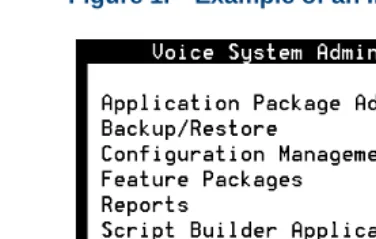
• The system displays menus, screens, and windows. Menus allow you to select options or to choose to view another menu, screen, or window
(Figure 1 on page xxxi). Screens and windows both show and request
system information (Figure 2 on page xxxi through Figure 5 on page
xxxiii).
About This Book Conventions Used in This Book
Figure 1. Example of an Intuity CONVERSANT Menu
About This Book Conventions Used in This Book
Figure 3. Example of an Intuity CONVERSANT Screen Showing Information
Figure 4. Example of an CONVERSANT Window Requesting Information
In order to install UnixWare, you must reserve a partition (a portion of your hard disk’s space) on your primary hard disk for the UNIX System. After you press ‘ENTER’ you will be shown a screen that will allow you to create new partitions, delete existing partitions or change the active partition of your primary hard disk (the partition that your computer will boot from).
WARNING: All files in any partition(s) you delete will be destroyed. If you wish to attempt to preserve any files from an existing UNIX System, do not delete its partition(s).
About This Book Conventions Used in This Book
Figure 5. Example of a CONVERSANT Screen Requesting Information
Keyboard and Telephone Keypad Representations
• Keys that you press on your terminal or PC are represented as small capitalized B OL D text. For example, an instruction to press the enter key is shown as:
Press E N T E R.
You may use a partition of your secondary hard disk. If you choose to use a partition of your secondary hard disk you will be shown a screen that will allow you to partition your secondary hard disk.
WARNING: All files in any partition(s) you delete will be destroyed.
If you choose to create a UNIX System partition on your secondary hard disk, it must be at least 40 MBs.
Your Options are:
1. Do not use a partition of the secondary hard disk for the UNIX System.
2. Use a partition of the secondary hard disk for the UNIX System.
About This Book Conventions Used in This Book
• Two or three keys that you press at the same time on your terminal or PC (that is, you hold down the first key while pressing the second and/or third key) are represented in small capitalized B O L D text. For example, an instruction to press and hold the Alt key while typing the letter “d” is shown as:
Press A LT + D.
• Function keys on your terminal, PC, or system screens, also known as soft keys, are represented as small capitalized B O L D text followed by the function or value of that key enclosed in parentheses. For example, an instruction to press function key 3 is shown as:
Press F 3 (Choices).
• Keys that you press on your telephone keypad appear in small capitalized
B O L D text. For example, an instruction to press the first key on your telephone keypad is shown as:
Press 1 to record a message.
Cross References
About This Book Conventions Used in This Book
Screen Displays • Values, system messages, field names, and prompts that appear on the screen, and simulated screen displays appear in typewriter-style constant-width type, as shown in the following examples:
Enter the number of ports to be dedicated to outbound traffic in the
Maximum Simultaneous Ports field.
Alarm Form Update was successful. Press <Enter> to continue.
• The sequence of menu options that you must select to display a specific screen or submenu is shown as follows:
Start at the Voice System Administration menu and select
:
In this example, you would access the Voice System Administration menu and select the Reports menu. From the Reports menu, you would then select the Message Log Report window.
> Message Log Report
About This Book Safety and Security Alert Labels
Other Typography • Commands and text you type in or enter appear in bold type, as in the following examples:
Enter change-switch-time-zone at the enter command: prompt. Type high or low in the Speed: field.
• Command variables are shown in bold italic type when they are part of what you must type in and blue italic type when they are not, for example:
Enter ch ma machine_name, where machine_name is the name of the call delivery machine you just created.
• Command options are shown inside square brackets, for example: Enter connect switchname [-d] [-b | -w]
Safety and Security Alert Labels
About This Book Getting Help
WARNING:
!
Indicates the presence of a hazard that if not avoided can cause death or severe personal injury.
!
DANGER:
Indicates the presence of a hazard that if not avoided will cause death or severe personal injury.
!
SECURITY ALERT:
Indicates the presence of a toll fraud security hazard. Toll fraud is the unauthorized use of a telecommunications system by an unauthorized party.
Getting Help
The Intuity CONVERSANT system provides online help to assist you during installation, administration, and application development tasks.
To use the online help:
About This Book Technical Assistance
The first time you press F 1, the system displays information about the currently active window or menu.
~ When you are in a window, the help explains the purpose of the window and describes its fields.
~ When you are in a menu, the help explains how to use menus. If you press F 1 again, the system displays a General Help screen that explains how to use the online help.
• Press F 2 (Choices) when you are in a field.
The system displays valid field choices either in a pop-up window or on the status line directly above the function keys.
• Press F 6 (Cancel) to exit the online help.
Technical Assistance
Web Site The following customer support web site contains resources where you can find solutions for technical problems:
About This Book Related Resources
• In Canada, call one of the following numbers, depending on your location:
~ 1-800-363-1882 for assistance in Quebec and eastern Canada
~ 1-800-387-4268 for assistance in Ontario and western Canada
• In any other country, call your local distributor or check with your project manager or systems consultant.
Related Resources
Additional documentation and training material is available for you to learn more about the Intuity CONVERSANT product.
Training To obtain training on the Intuity CONVERSANT product, contact the BCS Education and Training Center at one of the following numbers:
• Organizations within Lucent Technologies (904) 636-3261
• Lucent Technologies customers and all others (800) 255-8988 You can also view information on Intuity CONVERSANT training at the Global Learning Solutions (GLS) web site at one of the following web links:
• Organizations within Lucent Technologies
About This Book Related Resources
• Lucent Technologies customers and all others
http://www.lucenttraining.com
The courses listed below are recommended. Other courses are available.
• For technicians doing repairs on Intuity CONVERSANT V7.0 systems
~ BTT509H, CONVERSANT Installation and Maintenance Voice Information System
• For technicians and administrators
~ BTC344M, Intuity CONVERSANT V7 Administration Overview (CD-ROM)
• For application developers
~ BTC128H, Introduction to Script Builder
~ BTC166H, Introduction to Voice@Work
~ BTC204H, Intermediate Voice@Work
~ BTC301H, Advanced CONVERSANT Programming
About This Book Related Resources
Note: Always refer to the appropriate book for specific information on
planning, installing, administering, or maintaining an Intuity CONVERSANT system.
Additional Suggested Documentation
It is suggested that you also obtain and use the following book for information on security and toll fraud issues:
• GBCS Products Security Handbook, 555-025-600
For Troubleshooting Information
Basic troubleshooting information is in “Troubleshooting,” in the Intuity CONVERSANT System Reference, 585-313-205.
For Diagnostic Information
Instructions for conducting diagnostics are in “Diagnostics,” in the Intuity CONVERSANT System Reference, 585-313-205.
For Common System Procedures
About This Book Using the CD-ROM Documentation
For Installation Information
Instructions for installing or reinstalling system elements are in Intuity CONVERSANT System Version 7.0 New System Installation, 585-313-106.
Obtaining Printed Versions of the Documentation
See Documentation Ordering Information on page viii of Copyright and Legal
Notices for information on how to purchase Intuity CONVERSANT
documentation in printed form. You can also print documentation locally from the CD-ROM (see Printing the Documentation on page xliv).
Using the CD-ROM Documentation
About This Book Using the CD-ROM Documentation
Setting the Default Magnification
You can set your default magnification by selecting File | Preferences | General. We recommend the Fit Page option.
Adjusting the
Window Size On HP and Sun workstations, you can control the size of the reader window by using the -geometry argument. For example, the command string
acroread -geometry 900x900 mainmenu.pdf opens the main menu with a window size of 900 pixels square.
Hiding and Displaying Bookmarks
By default, the document appears with bookmarks displayed on the left side of the screen. The bookmarks serve as a hypertext table of contents for the chapter you are viewing. You can control the appearance of bookmarks by selecting View | Page Only or View | Bookmarks and Page.
Using the Button
Bar The button bar can take you to the book’s Index, table of contents, main menu, and glossary. It also lets you update your documents. Click the
corresponding button to jump to the section you want to read.
Using Hypertext Links
Hypertext links appears in blue underlined text. These links are shortcuts to other sections or books.
Navigating with
Double Arrow Keys The double right and double left arrows (Acrobat Reader window are the go-back and go-forward functions. The go-and ) at the top of the
About This Book Using the CD-ROM Documentation
Searching for Topics
Acrobat has a sophisticated search capability. From the main menu, select Tools | Search. Then select Master Index.
Displaying Figures If lines in figures appear broken or absent, increase the magnification. You might also want to print a paper copy of the figure for better resolution.
Printing the Documentation
Note: For information on purchasing printed copies of the documents,
see Obtaining Printed Versions of the Documentation on page xlii.
If you would like to read the documentation in paper form rather than on a computer monitor, you can print all or portions of the online screens.
Printing an Entire Document
To print an entire document, do the following:
1 From the documentation main menu screen, select one of the print-optimized documents. Print-print-optimized documents print two-screens to a side, both sides of the sheet on 8.5x11-inch or A4 paper.
2 Select File | Print.
About This Book How To Comment on This Book
5 Close the file. Do not leave this file open while viewing the electronic documents.
Printing Part of a Document
To print a single page or a short section, you can print directly from the online version of the document.
1 Select File | Print.
2 Enter the page range you want to print, or select Current. The document prints, one screen per side, two sides per sheet.
How To Comment on This Book
About This Book How To Comment on This Book
Comment Form A comment form, in paper and electronic versions, is available via the documentation CD-ROM. To use the comment form:
1 Select Comments from the Main Menu of the CD-ROM.
2 Follow the instructions provided on the CD-ROM to either:
~ Print the paper version of the form, complete it, and fax or mail it to us.
About This Book How To Comment on This Book
Contact Us Directly If you prefer not to use the comment form, you can contact us directly at the following address or fax number.
Lucent Technologies
GLS Information Development Division Room 22-2H15
11900 North Pecos Street Denver, CO 80234-2703 US Fax 1 303-538-1741
Note: Direct your correspondence to the attention of the Lucent
1
Getting Inside the Computer
Overview
This chapter provides the correct procedures for accessing the internal components of the MAP/40P.
Topics covered include:
• Protecting Against Damage from Electrostatic Discharge on page 2
• Power removal and restoration procedures
~ Removing Power from the MAP/40P on page 6
~ Restoring Power to the MAP/40P on page 10
• Computer chassis access procedures
~ Removing the Dress Cover on page 9
1
Getting Inside the Computer Protecting Against Damage from Electrostatic DischargeProtecting Against Damage from Electrostatic Discharge
!
CAUTION:
Read this section before unpacking the MAP/40P. You must observe proper grounding techniques to prevent the discharge of static electricity from your body into ESD-sensitive components.
Circuit cards and packaging materials that contain ESD-sensitive components are usually marked with a yellow-and-black warning symbol
(Figure 6 on page 2).
Figure 6. ESD Warning Symbol
ATTENTION OBSERVE PRECAUTIONS
FOR HANDLING
ELECTROSTATIC SENSITIVE
1
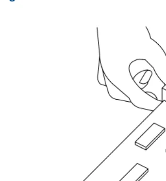
Getting Inside the Computer Protecting Against Damage from Electrostatic DischargeTo avoid damaging ESD-sensitive components, follow these rules:
• Handle ESD-sensitive circuit cards only after attaching a wrist strap to the bare wrist. Attach the other end of the wrist strap to a ground that terminates at the system ground, such as any unpainted metallic chassis surface.
• Handle a circuit card by the faceplate or side edges only (Figure 7 on
page 4 and Figure 8 on page 5).
!
CAUTION:
Ensure that your palm is not in contact with the non-component side of the board.
• Keep circuit cards away from plastics and other synthetic materials such as polyester clothing.
• Do not hand circuit cards to another person unless that person is grounded at the same potential level.
1
Getting Inside the Computer Protecting Against Damage from Electrostatic Discharge1
Getting Inside the Computer Protecting Against Damage from Electrostatic Discharge1
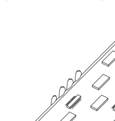
Getting Inside the Computer Removing Power from the MAP/40PFigure 9. ESD-Sensitive Area of an Electronic Component
Removing Power from the MAP/40P
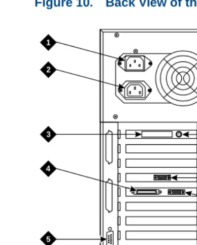
The MAP/40P requires a dedicated circuit with a dedicated circuit breaker. The power cord connects to the rear of the MAP/40P at the point labeled AC input receptacle (Figure 10 on page 7).
Before you begin any work in the MAP/40P you must disconnect the incoming power. Follow the procedure below to remove power from the MAP/40P.
1
Getting Inside the Computer Removing Power from the MAP/40PFigure 10. Back View of the MAP/40P
h2mxrear KLC 081997
1
2
3
4
6
7
8
9
10
5
1.AC power inlet receptacle
2.AC power supply outlet
3.External SCSI I/O connector
4.Parallel port
5.COM2
6.Keyboard connector
7.Power supply fan exhaust
8.Mouse connector - (not used)
9.Video connector
1
Getting Inside the Computer Removing Power from the MAP/40P1 Shut down the voice system. See “Administer the Voice System,” in “Common System Procedures,” in the Intuity CONVERSANT System Reference, 585-313-205.”
2 Shut down the Intuity CONVERSANT system. See “Shut Down the System,” in “Common System Procedures,” in the Intuity CONVERSANT System Reference, 585-313-205.
3 Turn off the monitor’s power switch.
The green or amber lamp on the front bottom of the monitor should be off.
4 Turn off the power switch on the front of the MAP/40P.
The green lamp, labeled POWER ON, on the front of the unit should be off.
5 Unplug the MAP/40P from the power outlet.
6 Remove the MAP/40P power cord from the AC input receptacle on the rear of the MAP/40P (Figure 10 on page 7).
1
Getting Inside the Computer Removing the Dress CoverRemoving the Dress Cover
The dress cover provides protection for the internal components of the MAP/40P. You must remove the dress cover to access these components.
WARNING:
!
Shut power off before removing the dress cover or access panel of the MAP/40P. See Removing Power from the MAP/40P on page 6.
1 Ensure that the MAP/40P tower configuration is in an upright position on the support base.
2 Remove the six screws located along the bottom of the MAP/40P, one located midway up the left side toward the front, and one in the middle of the rear of the chassis.
Note: You will need a No. 2 Phillips screwdriver.
There are three screws on each side of the MAP/40P.
3 Remove the screw holding the dress cover to the rear of the MAP/40P.
1
Getting Inside the Computer Replacing the Dress CoverReplacing the Dress Cover
1 Place the MAP/40P in the upright position.
2 Slide the dress cover over the unit.
3 Replace and tighten the eight dress cover retaining screws.
Restoring Power to the MAP/40P
The MAP/40P requires a dedicated power line. The power cord connects to the rear of the MAP/40P at the point labeled Input Receptacle (Figure 10 on
page 7).
Follow the procedure below to restore power to the MAP/40P.
1 Place the MAP/40P power cord in the AC input receptacle on the rear of the unit (Figure 10 on page 7).
2 Plug the MAP/40P power cord into the designated power outlet.
3 Turn on the power switch on the front of the MAP/40P.
The green lamp, labeled POWER ON, on the front of the unit should be lit.
4 Turn on the monitor’s power switch.
2
Installing or Replacing Circuit
Cards
Overview
The purpose of this chapter is to ensure that:
• Circuit cards are installed correctly
• Resource options are set correctly Topics covered include:
• Configuring circuit cards in the MAP/40P
• Types of circuit cards
• General steps for circuit card installation
• Specific procedures for installation of standard and optional MAP/40P circuit cards
2
Installing or Replacing Circuit Cards General ProceduresGeneral Procedures
The general procedures include:
• Removing a Circuit Card on page 12
• Installing a Circuit Card on page 14
Removing a Circuit Card
!
CAUTION:
Observe proper electrostatic discharge precautions when you handle computer components. Wear an antistatic wrist strap that touches your bare skin and connect the strap cable to an earth ground. See Protecting Against
Damage from Electrostatic Discharge on page 2, in Chapter 1, Getting Inside
the Computer for detailed electrostatic discharge precautions.
To remove a circuit card, do the following.
1 Verify that the replacement equipment is on site and appears to be in usable condition, with no obvious shipping damage.
Note: If the circuit card being replaced is defective, note all symptoms of
2
Installing or Replacing Circuit Cards General Procedures2 If the system is in service, do the following:
a Stop the voice system. See “Administer the Voice System,” in
“Common System Procedures,” in the Intuity CONVERSANT System Reference, 585-313-205.
b Shut down the voice system. See “Administer the Voice System,” in “Common System Procedures,” in the Intuity CONVERSANT System Reference, 585-313-205.
c Shut down the Intuity CONVERSANT system. See “Shut Down the System,” in “Common System Procedures,” in the Intuity
CONVERSANT System Reference, 585-313-205.
3 Remove power from the MAP/40P. See Removing Power from the
MAP/40P on page 6 in Chapter 1, Getting Inside the Computer .
4 Remove the dress cover. See Removing the Dress Cover on page 9 in
Chapter 1, Getting Inside the Computer .
5 Locate the card to be replaced within the card cage. Disconnect any attached cables. Note the connectivity of each cable.
2
Installing or Replacing Circuit Cards General Procedures8 Remove the circuit card from the backplane slot by gently pulling at the top corners of the circuit card.
Note: The backplane connector slots are labeled 1 through 20. Make
sure to install the replacement card in the same backplane slot.
9 Remove the circuit card from the MAP/40P chassis.
!
CAUTION:
Hold the circuit card carefully by the edges and place it on a grounded mat.
See Protecting Against Damage from Electrostatic Discharge on page 2 in
Chapter 1, “Getting Inside the Computer,” for detailed electrostatic discharge precautions.
Installing a Circuit Card
!
CAUTION:
Observe proper electrostatic discharge precautions when you handle computer components. Wear an antistatic wrist strap that touches your bare skin and connect the strap cable to an earth ground. See Protecting Against
Damage from Electrostatic Discharge on page 2 in Chapter 1, Getting Inside
the Computer for detailed electrostatic discharge precautions.
To install a circuit card, do the following:
2
Installing or Replacing Circuit Cards General ProceduresNote: Keep the package and all ESD protective wrapping. If you must
return a card for repair, re-use of the replacement unit packaging is necessary to meet the manufacturer’s warranty.
2 Verify the circuit card switch and jumper settings. Ensure address switches and jumpers are set to match the old card.
Note: See the specific instructions, listed later in this chapter, for each
type of circuit card being installed then continue with step 3.
3 Holding the circuit card by its upper corners, slide the card into the backplane connector slot position from which you removed the damaged card.
4 Apply even pressure to both corners of the circuit card until it is locked into the backplane.
5 Secure the circuit card faceplate into position by replacing the retaining screw.
6 Return all cables on the new card. Make sure these cables are attached to their proper terminations.
2
Installing or Replacing Circuit Cards Settings for Optional Circuit Cards9 Apply power to the unit. See Restoring Power to the MAP/40P on page 10, in Chapter 1, Getting Inside the Computer .
10 Reboot the Intuity CONVERSANT system. See “Reboot the System,” in “Common System Procedures,” in the Intuity CONVERSANT System Reference, 585-313-205.
Settings for Optional Circuit Cards
!
CAUTION:
Observe proper electrostatic discharge precautions when you handle computer components. Wear an antistatic wrist strap that touches your bare skin and connect the strap cable to an earth ground. See Protecting Against
Damage from Electrostatic Discharge on page 2, in Chapter 1, Getting Inside
the Computer for detailed electrostatic discharge precautions.
This section provides the following information on the optional feature circuit cards:
• Switch and jumper settings
2
Installing or Replacing Circuit Cards Settings for Optional Circuit CardsIn general, circuit cards are not preset at the factory. You must set the switches and jumpers (resource options) BEFORE you install the cards. When you set the switches according to the instructions in this book, remember that OFF is equivalent to open and ON is equivalent to closed.
Tip/Ring Circuit Cards
The Tip/Ring circuit cards provide the channels which are used by the Intuity CONVERSANT system. The MAP/40P accommodates eleven Tip/Ring circuit cards. The Tip/Ring circuit card can be any of the following types:
• AYC29 (IVP6-IA)
• AYC10 (IVC6)
• AYC30 (NGTR)
The following section covers the resource option settings for each type of T/R card. Many of the figures referenced illustrate settings for more than one type of T/R card.
The six switches on Switch Bank A adjust the termination impedance that each Tip/Ring interface presents to the network. This adjustment is
2
Installing or Replacing Circuit Cards Settings for Optional Circuit CardsIn general, you should leave all switches on Switch Bank A in the factory default “OPEN” position. If the system shows problems such as not
recognizing touch tones, touch-tone simulation by outgoing speech (speech abruptly stops during playback), or unreliable detection of touch tones during playback (playback does not stop when a touch tone is entered), moving the switch that corresponds to the channel exhibiting the conditions to the “CLOSED” position may solve the problem.
2
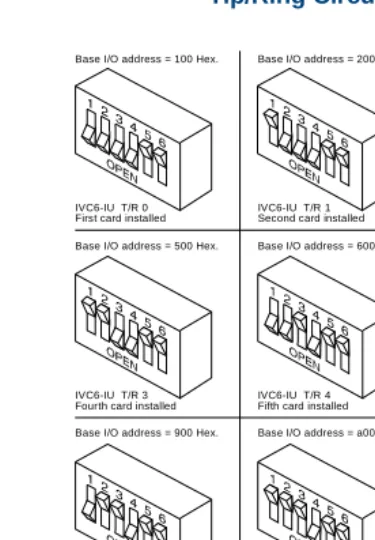
Installing or Replacing Circuit Cards Settings for Optional Circuit CardsFigure 11. Settings for Switches on the IVP6-IA (AYC29), and IVC6 (AYC10) Tip/Ring Circuit Cards T/R-0 through T/R-7
Base I/O address = 100 Hex.
IVC6-IU T/R 0 First card installed
Base I/O address = 200 Hex.
IVC6-IU T/R 1 Second card installed
Base I/O address = 300 Hex.
IVC6-IU T/R 2 Third card installed Base I/O address = 500 Hex.
IVC6-IU T/R 3 Fourth card installed
Base I/O address = 600 Hex.
IVC6-IU T/R 4 Fifth card installed
Base I/O address = 700 Hex.
Base I/O address = b00 Hex. IVC6-IU T/R 5 Sixth card installed
IVC6-IU T/R 8 Ninth card installed Base I/O address = 900 Hex.
Base I/O address = d00 Hex. IVC6-IU T/R 6 Seventh card installed
Base I/O address = a00 Hex.
2
Installing or Replacing Circuit Cards Settings for Optional Circuit CardsIVP6-IA (AYC29) Circuit Card
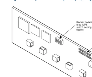
The IVP6-IA (AYC29) circuit card (Figure 12 on page 21) provides six channels.
Note: This circuit card contains switches that you must set before you
install the circuit card in the MAP/40P.
Each Tip/Ring card in the system must have a unique address. To set these addresses, the switches must be configured properly. Figure 11 on page 19
2
Installing or Replacing Circuit Cards Settings for Optional Circuit CardsFigure 12. Layout of the IVP6 (AYC29) Tip/Ring Circuit Card
Modular jacks Audio TDM bus
2
Installing or Replacing Circuit Cards Settings for Optional Circuit CardsIVC6 (AYC10) Circuit Card
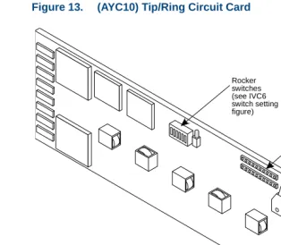
The IVC6 (AYC10) circuit card (Figure 13 on page 23) provides six channels.
Note: This circuit card contains switches that you must set before you
install the circuit card in the MAP/40P.
Each Tip/Ring card in the system must have a unique address. To set these addresses, the switches must be configured properly. Figure 11 on page 19
2
Installing or Replacing Circuit Cards Settings for Optional Circuit CardsFigure 13. (AYC10) Tip/Ring Circuit Card
8-pin modular jacks Audio input TDM bus
terminator SIPs Rocker
2
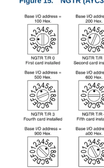
Installing or Replacing Circuit Cards Settings for Optional Circuit CardsNGTR (AYC30) Circuit Card
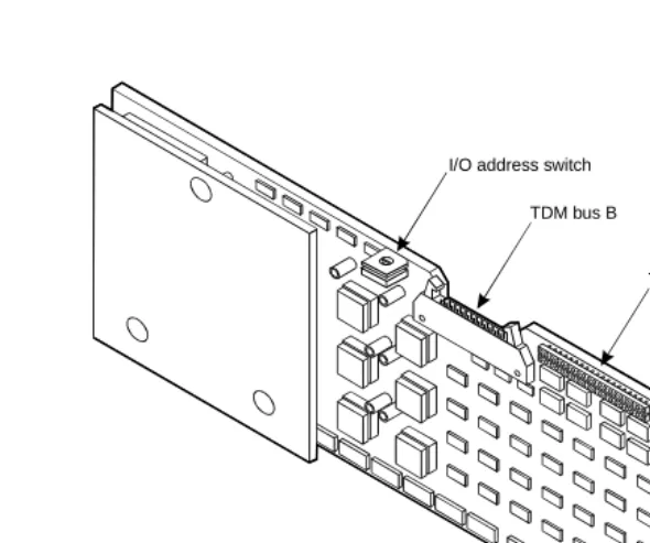
The NGTR (AYC30) circuit card (Figure 14 on page 25) provides six channels.
Note: This circuit card contains switches that you must set before you
install the circuit card in the MAP/40P.
2
Installing or Replacing Circuit Cards Settings for Optional Circuit CardsFigure 14. NGTR (AYC30)
I/O address switch
TDM bus B
TDM bus A TDM bus terminator SIPs
8-pin modular jacks
2
Installing or Replacing Circuit Cards Settings for Optional Circuit Cards2
Installing or Replacing Circuit Cards Settings for Optional Circuit CardsInstalling the Tip/Ring Circuit Card Driver
Note: If the Tip/Ring circuit cards are not recognized when the voice
system is started or if other problems are noticed with the Tip/Ring circuit card driver, it may be necessary to remove and reinstall the Tip/Ring circuit card driver.
Occasionally dynamically loadable drivers fail to load into the UnixWare kernel properly.
To install the Tip/Ring circuit card driver, do the following:
1 Stop the voice system. See “Administer the Voice System,” in “Common System Procedures,” in the Intuity CONVERSANT System Reference, 585-313-205.
2 Run the Hardware Resource Allocator to determine the configuration and placement of the Tip/Ring circuit cards to be installed. See Adding
Hardware to an Existing Configuration on page 468 in Appendix A,
System Configuration.
3 If you are not already logged in as root, do so now.
4 Enter pkgadd -d diskette1
2
Installing or Replacing Circuit Cards Settings for Optional Circuit Cards5 Insert the diskette labeled “Tip/Ring Board Driver 1 of 1” into the diskette drive.
6 Press E N T E R.
The system displays the following message:
Installation in progress -- do not remove the diskette. The following packages are available:
1. tipring INTUITY Tip/Ring Board Driver (i486)
Select package(s) you wish to process (or ‘all’ to process all packages). (default: all) [?,??,q]:
7 Press E N T E R.
The system displays the following message:
PROCESSING:
Set: INTUITY Tip/Ring Board Driver (tipring) from <diskette1>
INTUITY Tip/Ring Board Driver (i486)
2
Installing or Replacing Circuit Cards Settings for Optional Circuit CardsThe system displays several status messages and then the following message:
Please enter the IRQ:
8 Enter the IRQ provided by the Hardware Resource Allocator.
The system displays several status messages and then the following message:
Installation of INTUITY Tip/Ring Board Driver (tipring) was successful.
Insert diskette into Floppy Drive 1. Type [go] when ready,
or [q] to quit: (default: go)
9 Enter q
10 Remove the diskette labeled “Tip/Ring Board Driver 1 of 1” from the diskette drive.
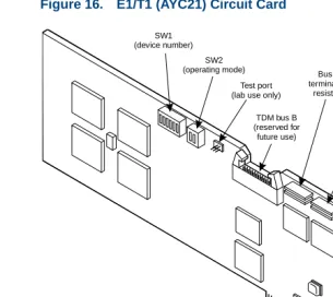
E1/T1 Circuit Card
2
Installing or Replacing Circuit Cards Settings for Optional Circuit CardsFigure 16. E1/T1 (AYC21) Circuit Card
TDM bus B (reserved for
future use)
TDM bus A Bus B terminating resistors Bus A terminating resistors LED 8-pin modular jack TX connector (signal out) RX connector (signal in) SW1 (device number) SW2 (operating mode) Test port (lab use only)
J8 (shield ground) J7
2
Installing or Replacing Circuit Cards Settings for Optional Circuit CardsJumper Settings Figure 17 on page 31 shows the location and correct setting of the E1/T1 circuit card jumpers.
Figure 17. AYC21 Jumper Settings
Switch Settings There are two sets of switches on the E1/T1 circuit card. Figure 18 on page
32, Figure 19 on page 33, and Figure 20 on page 33 show the correct switch
settings.
68302
J12 (IRQ select) J8
Ground RX outer conductor
Ground TX outer conductor
2
Installing or Replacing Circuit Cards Settings for Optional Circuit Cards2
Installing or Replacing Circuit Cards Settings for Optional Circuit CardsFigure 19. AYC21 Operating Mode Switch Settings for E1 Operation
Figure 20. AYC21 Operating Mode Switch Settings for T1 Operation
CEPT/E1 75 ohm, BNC jack
2
Installing or Replacing Circuit Cards Settings for Optional Circuit CardsInstalling the E1/T1 Circuit Card Driver
Note: If the E1/T1 circuit cards are not recognized when the voice
system is started or if other problems are noticed with the E1/T1 circuit card driver, it may be necessary to remove and reinstall the E1/T1 circuit card driver.
Occasionally dynamically loadable drivers fail to load into the UnixWare kernel properly.
To install the E1/T1 circuit card driver, do the following:
1 If you are not already logged in as root, do so now.
2 Stop the voice system. See “Administer the Voice System,” in “Common System Procedures,” in the Intuity CONVERSANT System Reference, 585-313-205.
3 Enter pkgadd -d diskette1
The system displays the following message:
Insert diskette into Floppy Drive 1. Type [go] when ready,
or [q] to quit: (default: go)
4 Insert the diskette labeled “T1/E1 Board Driver 1 of 3” into the diskette drive.
2
Installing or Replacing Circuit Cards Settings for Optional Circuit CardsThe system displays the following message:
Installation in progress -- do not remove the diskette. The following packages are available:
1. t1driver INTUITY T1/E1 Board Driver (i486)
Select package(s) you wish to process (or ‘all’ to process all packages). (default: all) [?,??,q]:
6 Press E N T E R.
The system displays the following message:
PROCESSING:
Set: INTUITY T1/E1 Board Driver (t1driver) from <diskette1> INTUITY T1/E1 Board Driver
(i486)
Using </> as the package base directory. Lucent Technologies Inc.
The system displays several status messages and then the following message:
2
Installing or Replacing Circuit Cards Settings for Optional Circuit CardsInsert diskette 2 of 3 into Floppy Drive 1. Type [go] when ready,
or [q] to quit: (default: go)
7 Remove the diskette labeled “T1/E1 Board Driver 1 of 3” from the diskette drive.
8 Insert the diskette labeled “T1/E1 Board Driver 2 of 3” into the diskette drive.
9 Press E N T E R.
The system displays several status messages and then the following message:
READY TO PROCESS:
Package: INTUITY T1/E1 Board Driver (t1driver) diskette 3 of 3
Insert diskette 3 of 3 into Floppy Drive 1. Type [go] when ready,
or [q] to quit: (default: go)
10 Remove the diskette labeled “T1/E1 Board Driver 2 of 3” from the diskette drive.
11 Insert the diskette labeled “T1/E1 Board Driver 3 of 3” into the diskette drive.
2
Installing or Replacing Circuit Cards Settings for Optional Circuit CardsThe system displays several status messages and then the following message:
Installation of T1/E1 Board Driver (t1driver) was successful.
Insert diskette into Floppy Drive 1. Type [go] when ready,
or [q] to quit: (default: go)
13 Enter q
14 Remove the diskette labeled “T1/E1 Board Driver 3 of 3”from the diskette drive.
Speech and Signal Processor (AYC43) Circuit Card
Note: The SSP circuit card (Figure 21 on page 38) contains switches
2
Installing or Replacing Circuit Cards Settings for Optional Circuit CardsFigure 21. Speech and Signal Processor Circuit Card
2
Installing or Replacing Circuit Cards Settings for Optional Circuit CardsSwitch Settings There are two types of switches on the SSP circuit card:
• Two-position switches
• Rotary switch
Two-Position Switch Settings
Figure 22 on page 39 shows the location of the SSP circuit card two-position
switches. If the SSP circuit card is not located at the end of the TDM bus, both switches should be set to open. The switches should be set to closed if the SSP circuit card is located at the end of the bus.
Figure 22. SSP Circuit Card Two-Position Switches (Set for a Placement in the Middle of the TDM Bus)
Rotary Switch Settings
2
Installing or Replacing Circuit Cards Settings for Optional Circuit CardsFigure 23. SSP Circuit Card Rotary Switch
Table 1 on page 40 shows the rotary switch settings for the subsequent SSP
circuit cards installed.
Table 1. SSP Circuit Card Rotary Switch Setting
I/O Address OS Index Rotary Switch Setting
d20 8 0
d28 9 1
d30 10 2
d38 11 3
920 12 4
928 13 5
2
Installing or Replacing Circuit Cards Settings for Optional Circuit CardsMemory The SSP circuit card is equipped with 16 Mbytes of memory contained on a dual in-line memory module (DIMM). The DIMM is located in the lower portion of the SSP circuit card (Figure 21 on page 38).
!
CAUTION:
The DIMM is not field serviceable.
Installing the ASP
Driver Package To install the ASP circuit card driver, do the following:
1 Stop the voice system. See “Administer the Voice System,” in “Common System Procedures,” in Intuity CONVERSANT System Reference, 585-313-205.
2 At the UNIX prompt, enter pkgadd -d diskette1
930 14 6
938 15 7
Table 1. SSP Circuit Card Rotary Switch Setting
I/O Address OS Index Rotary Switch Setting
2
Installing or Replacing Circuit Cards Settings for Optional Circuit CardsThe system displays the following message:
Insert diskette into Floppy Drive 1. Type [go] when ready,
or [q] to quit: (default: go)
3 Insert the diskette labeled “ASP Driver Package 1 of 2” into the diskette drive.
4 Press E N T E R.
The system displays the following message: