Mathematical Modeling and Hybrid Heuristic for Unequal
Size Facility Layout Problem
Nurul Nadia Nordin*, Zaitul Marlizawati Zainuddin*, Sutinah Salim and Raja Rajeswari d/o Ponnusamy
Faculty of Science, Universiti Teknologi Malaysia, 81310 UTM Skudai, Malaysia.
* Author to whom correspondence should be addressed; E-mail: [email protected] or [email protected]
Received: 11 March 2009, Revised: 11 May 2009 Online Publication: 29 May 2009
ABSTRACT
The facility layout design has been regarded as the key to improve plant productivity, which are relevant to both manufacturing and service sectors. Facility Layout Problems (FLPs) are known to be NP-hard problems; various optimization approaches for small problems and heuristic approaches for the larger problems have been proposed to elucidate the problem. A mathematical model is developed for the unequal size facility layout problem with fixed flow between departments. We are considering the orientations of the departments with various sizes and aims to minimize the distance traveled by people, material, and other supporting services in the safest and most effective manner. Some of the constraints considered in the modeling are the restricted areas, reserved departmentry locations, and also the irregularity of the shapes of manufacturing layout. This paper focuses on the mathematical model and the solution of the non-quadratic assignment problem (non-QAP) by hybridizing the meta-heuristic methods i.e. Genetic Algorithm (GA) and Simulated Annealing (SA). This work could be used in future as a reference for those researchers interested in tackling this challenging unequal facility layout problem.
| Unequal size layout | non-Quadratic Assignment Problem | Genetic Algorithm | Simulated Annealing |
1. Introduction
Facility Layout Problems (FLPs) are known to be NP-hard problems; various optimization approaches for small problems and heuristic approaches for the larger problems have been proposed to elucidate the problem. Facility layout is the arrangement of work space which, in general terms smoothes the way to access facilities that have strong interaction. Facilities are of crucial importance to organizations because, usually, they represent the largest and most expensive assets of the organization [1]. The proper optimization of facility layout has gain more attention in recent years due to the quest for increased competitiveness. Facility layout design involves the physical arrangement of a number of interacting facilities on a certain planar site [2]. A facility in this context means a physical entity used for facilitating the processing of any job. For instance, a work center, a machine tool, a department, a manufacturing cell, etc. No matter what the facilities are, the common characteristic that is always a major concern in the design phase for all facilities is the area and shape occupied by the facility. Optimal design of the facility layout is one of the most critical issues that the designer has to solve in the early
A
rt
ic
le
J
ournal of
F
undamental
S
ciences
Available online at
http://www.ibnusina.utm.my/jfs
stage of the manufacturing system design. While setting up a manufacturing system, the designer has to organize a floor plan layout for all facilities so that an objective is fulfilled such as minimizing the distance travelled.
A well design facility layout allows the manufacturing or service system to quickly respond to the changes in product and service design. It is equally important to the implementation of the manufacturing system and to its daily operation. Facility layout design problems are usually viewed as an optimization problem and the best layout is picked out by optimizing some measure of performances subject to a set of constraints [3]. The Facility Layout Problem (FLP) is one of the best-studied problems in the field of combinatorial optimization. A number of formulations have been developed for the problem. More particularly the FLP has been modelled as quadratic assignment problem (QAP), linear integer programming problem, mixed integer programming problem and graph theoretic problem.
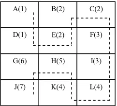
In this paper, the FLP with unequal area requirements and different geometric shape constraint is addressed. We will focus on modeling and solving two dimensional unequal size facility layout problems, categorized as non-QAP. The unequal-sized layout problem may be modeled as a non-QAP problem by dividing the areas into grids with equal-sized squares [4]. Each department would occupy different numbers of squares depending on its size. This is seen in Figure 1 where department 2 occupies squares B, C and E while department 1 occupies squares A and D. The shapes of the departments can be made more accurate by using smaller grids. But this will further increase the size of the problem and the resultant computation time.
A mathematical model is introduced to study the layout of departments for the typical job shop in manufacturing environments. The objective is to minimize total distance travelled with the fixed volume of flow while satisfying area and geometric constraints of each facility. In addition, the formulation also considers the placement of the departments according to prediscribed sequence, the constraints of restricted areas and reserved departmentry locations, the irregularity of the shape of manufacturing plants, etc. An approach derived from heuristic methods, i.e., Genetic Algorithm (GA) and Simulated Annealing (SA) is developed to provide the near optimal solution to the facility layout problems.
Figure 1: A block layout constructed based on an unequal facility problem
2. Mathematical model
Facility layout design is the assignment of M departments to N departmentry locations (N ≥ M) in a manufacturing plant. The facility layout algorithm must generate feasible layouts that satisfy the constraints imposed. It is important to note that any solution procedure should generate a layout that requires minimal manual adjustment and should be sensitive to varying shapes and sizes of individual machines or department. Indeed the following aspect of the manufacturing system are considered:
A(1) B(2) C(2)
F(3) E(2)
D(1)
G(6) H(5)
K(4) J(7)
I(3)
a. During manufacturing process, material flow is fixed from one department to the next appropriate departments, until all the processes are completed.
b. The objective is to minimize the sum of total product between flows and distance traveled from one department to another.
c. Each facility has to be assigned only once to a location on the floor plan and its area cannot be overlapped with one another.
d. Margin between each department.
The model is also based on the following assumptions:
1. All departments are of fixed rectangular geometry.
2. Each department can assume one of two orientation, horizontal or vertical. 3. Distance between departments is measured rectilinearly from their centroids.
4. A fixed rectangular boundary of size W (floor width) x H (floor height) will surround all departments with no overlapping.
5. All the dimensions must be integer measurements.
6. For a type of departments, we can arrange all this departments besides or below or above each others or both ways in a layout.
The following notations are used in the development of the mathematical model:
ij
d
rectangular distance between departmentry locationsi
andj
(
i
,
j
=
1
,
2
,
K
,
N
and
i
≠
j
)
(assuming that0
=
ii
d
for all i)ij
f
flow of the materials between facilities i and j is fixed to 1 (assuming thatf
ii=
0
for all i)M
total number of departments contained in the manufacturing systemN
number of departmentry locations contained in the plant configuration layouti
O
orientation of departmenti
L
length of the whole manufacturing plantW
width of the whole manufacturing planti
α
length of departmenti
(where,α
i≤
β
i)i
β
width of departmenti
H
alarge value,H
≥
LW
A
margin between each departmenti
x
centroid of departmenti
inx
directioni
y
centroid of departmenti
iny
direction = n orientatio horizontal n orientatio vertical Oi , 0 , 1 = j department of right left be not may or may i department then j department of right left is i department then
bleftright ij ) ( , 0 ) ( , 1 ) ( = j department of above below be not may or may i department then j department of above below is i department then
The mathematical model for unequal size FLP with all the aspects and assumptions mentioned is shown below.
Min
Z
= ijn j ij n i
d
f
∑
∑
= =1 1(1)
subject to
(
O
)
A
O
x
=
+
−
+
2
1
2
1 1 1 1 1β
α
(2)(
O
)
A
O
y
=
+
−
+
2
1
2
1 1 1 1 1α
β
(3) above ij below ij left ij j j j j j i i i ii
Hb
Hb
Hb
O
O
x
A
O
O
x
+
+
−
+
≤
−
−
−
+
+
+
2
)
1
(
2
2
2
)
1
(
2
β
α
β
α
(4) above ij below ij right ij i i i i i j j j jj
Hb
Hb
Hb
O
O
x
A
O
O
x
+
+
−
+
≤
−
−
−
+
+
+
2
)
1
(
2
2
2
)
1
(
2
β
α
β
α
(5) above ij left ij right ij j j j j j i i i ii
Hb
Hb
Hb
O
O
y
A
O
O
y
+
−
+
+
≤
−
−
−
+
+
+
2
2
)
1
(
2
2
2
)
1
(
α
β
α
β
(6) below ij left ij right ij i i i i i j j j jj
Hb
Hb
Hb
O
O
y
A
O
O
y
+
−
+
+
≤
−
−
−
+
+
+
2
2
)
1
(
2
2
2
)
1
(
α
β
α
β
(7)1
=
+
+
+
above ij below ij right ij leftij
b
b
b
b
(8)}
1
,
0
{
,
,
,
,
above∈
ij below ij right ij left ij
i
b
b
b
b
O
(9)
i
y
x
i,
i≥
0
∀
(10)
}
;
,...,
1
;
1
,...,
2
|
)
,
{(
i
j
i
=
N
−
j
=
i
+
N
i
≠
j
(11)The objective function (1) minimizes the sum of total product between flows and distance traveled from one department to another from their centroids by using rectilinear distance, xi−xj + yi−yj . It is not necessary
that
x
1 andy
1 to be the centroid for department 1. It represents the centroid for the first cell to be placed in the layout. In the model, the constraints perform the tasks of preventing departments from overlapping, restrictingdepartment extremities to the layout interior and defining the domains of variables. Constraints (2) and (3) is used to ensure that the first department is placed on a fixed point,
( )
0
,
0
. It represent the centroid for the first cell to be placed in the layout. While constraints (4) to (7) are disjunctive constraints that prevent every pair of departments from overlapping. Besides that, a departmenti
can be either left of, right of, above or below a departmentj
and there is a constraint for each case. Therefore whichever the case may be, the appropriateb
ij3. Hybrid Algorithm of Genetic Algorithm (GA) - Simulated Annealing (SA)
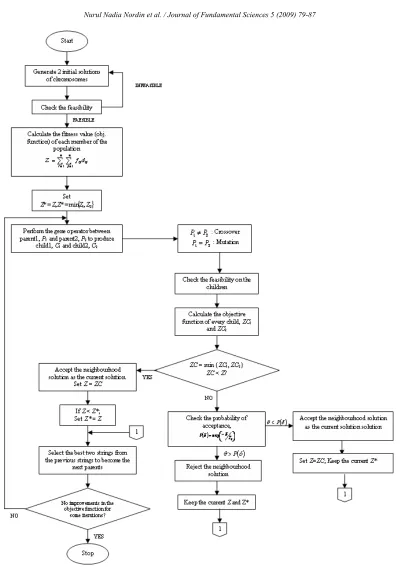
In this paper, we introduces the algorithm developed to solve the facility layout problem using the hybridization of Genetic Algorithm (GA) and Simulated Annealing (SA). The mating ritual for GA is based on the work done by Jasmit Singh Kochhar et al [4]. Figure 2 illustrated the flowchart of this algorithm.
3.1. The Algorithms
Step 1 Randomly generate 2 initial solutions of chromosomes;
Step 2 Check the feasibility, if infeasible;
go to Step 1; else go to Step 3;
Step 3 Calculate the fitness value or the objective function of each member of the population,
ij n
i n
j ij
d
f
Z
∑∑
= =
=
1 1
;
Set
Z
*
=
Z
;Z
*
=
min
{
Z
1,
Z
2}
Step 4 Perform the gene operator between parent1,
P
1 and parent2,P
2 to produce child1,C
1 and child2,2
C
based on the following condition;i. If
P
1≠
P
2 - Crossover; ii. IfP
1=
P
2 - Mutation;Step 5 Do the feasibility check on the children if infeasible;
go to Step 4; else go to Step 6;
Step 6 Calculate the objective function of every child,
ZC
1 andZC
2;Step 7 If the neighbourhood solution,
ZC
=
min
{
ZC
1,
ZC
2}
is better thanthe current solution,Z
ZC
<
;Accept the neighbourhood solution as the current solution, Set
Z
=
ZC
;If
Z
<
Z
*, setZ
*=
Z
;Else, check the probability of acceptance,
P
( )
δ
=
exp
(
−
δ
T
k)
;If
θ
>
P
( )
δ
;Reject the neighbourhood solution; Keep the current
Z
andZ
*; Else,Accept the neighbourhood solution as the current solution;
Set
Z
=
ZC
; Keep the currentZ
*;Step 8 Select the best two strings from the previous strings to become the next parents;
3.2. The Mating Ritual
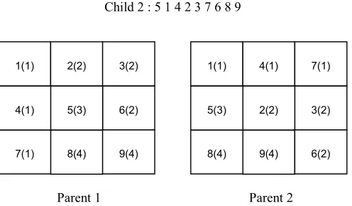
For ease and convenience, we shall describe the GA mating ritual [4] as this will be used in our algorithm. We will apply the crossover operator when where a department is randomly chosen from the department set corresponding to the first parent string and is placed in a (new) child department set in the same location as it exists in the parent. The departments missing in the new set are filled in the same order that they appear in the second parent. Once again, the process is repeated by swapping the positions of two parents to create another child department set from the same set of parents. For example, consider the following parents strings and Figure 3 which shows the number of squares assigned to each department. Note that the number in bracket is the number of respective department.
Parent 1 : 1 2 3 4 5 6 7 8 9 Parent 2 : 1 4 7 5 2 3 8 9 6
To construct the first child, one unequal department is randomly picked from the first department set (corresponding to the first parent string) and placed on an empty set. The partial department order is shown below.
Child 1 : _ 2 3 _ _ 6 _ _ _ Child 2 : 1 4 7 _ _ _ _ _ _
To complete the set, the missing departments are placed in the same order as they appear in the second department set and the layout is shown in Figure 4.
Child 1 : 1 2 3 4 7 6 5 8 9 Child 2 : 1 4 7 2 3 5 6 8 9
As the mutation operator randomly swaps two departments in a solution, we will apply this operator when
2 1
P
P
=
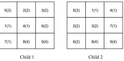
. Assume mutation randomly swaps department 1 and 3. The mutated department set is converted to a corresponding child string as shown below and it is illustrated in Figure 5.Child 1 : 5 2 3 1 4 6 7 8 9 Child 2 : 5 1 4 2 3 7 6 8 9
Parent 1 Parent 2
Figure 3: Mating ritual
1(1) 2(2) 3(2)
6(2)
8(4) 7(1)
5(3) 4(1)
9(4)
1(1) 4(1) 7(1)
3(2)
9(4) 8(4)
2(2) 5(3)
Child 1 Child 2
Figure 4: Mating ritual (crossover)
Child 1 Child 2
Figure 5: Mating ritual (Mutation)
3.3. Stopping Criteria
The stopping conditions employed to stop GA-SA from doing further iteration is the quality of the solution. The algorithm will stop the operation when the value of the best objective function, Z* does not change (no improvement) within a given number of iterations.
4. Conclusion
A mathematical model has been developed to examine the departments’ layout for the particular job shop manufacturing environments with the mentioned aspects and assumptions. This paper has also presented the use of hybrid algorithm (GA - SA) as a general methodology to solve the facility layout problem under consideration.
Using the model and algorithm proposed in this study as the framework, further research may generate good solutions of larger problems with more realistic constraints and objectives such as aisles and obstacles can be represented as unmovable departments and participate in part flows. Meta-heuristic techniques are seen to be the most promising for real implementations since the used of these techniques make it possible for researchers to tailor the objective function and constraints to more accurately depict the real problems, despite any non-linearity that may arise.
5(3) 2(2) 3(2)
6(2)
8(4) 7(1)
4(1) 1(1)
9(4)
5(3) 1(1) 4(1)
7(1)
8(4) 6(2)
3(2) 2(2)
9(4) 1(1) 2(2) 3(2)
6(2)
8(4) 5(3)
7(1) 4(1)
9(4)
1(1) 4(1) 7(1)
5(3)
8(4) 6(2)
3(2) 2(2)
5. Acknowledgement
The authors would like to thank INTEL Corporation for the sponsorship of the research.
6. References
[1] Canen, A.G. and Williamson, G.H., Facility layout overview: towards competitive advantage. Facilities, 14, (1996). 5-10.
[2] R. L. Francis, L. F. McGinnis, L. White, Facility Layout and Location: An Analytical Approach, 2nd Edition, 1992.
[3] Cheng, R., Gen, M., and Tozawa, T., Genetic search for facility layout design under interflows uncertainty. IEEE Transactions, 95, (1995) 400-405.