Jurnal Teknologi, 42(D) Jun. 2005: 95–112 © Universiti Teknologi Malaysia
1&2
Precision and Intelligent Systems Research Group, Department of Mechatronics Enginering, International Islamic, University Malaysia, Jalan Gombak, 53100 Kuala Lumpur, Malaysia. Tel: +603-2056-4469, Fax: +603-2056-4433.
Email: [email protected], [email protected]
FUZZY ANTI-WINDUP SCHEME FOR PRACTICAL CONTROL OF POINT-TO-POINT (PTP) POSITIONING SYSTEMS
WAHYUDI1 & ABDULGHANI ALBAGUL2
Abstract. The positioning systems generally need a controller to achieve high accuracy, fast response and robustness. In addition, ease of controller design and simplicity of controller structure are very important for practical application. For satisfying these requirements, nominal characteristic trajectory following (NCTF) controller has been proposed as a practical PTP positioning control. However, the effect of actuator saturation cannot be completely compensated due to integrator windup because of plant parameter variations. This paper presents a method to improve the NCTF controller for overcoming the problem of integrator windup by adopting a fuzzy anti-windup scheme. The improved NCTF controller is evaluated through simulation using dynamic model of a rotary positioning system. The results show that the improved NCTF controller is adequate to compensate the effect of integrator windup.
Keywords: Positioning, point-to-point, fuzzy, anti-windup, compensation, controller, robustness
Abstrak. Sistem kedudukan biasanya memerlukan sebuah kawalan untuk mencapai ketepatan yang jitu, tindakbalas yang pantas dan tegap. Di samping itu, rekaan dan struktur kawalan yang ringkas dan mudah adalah amat penting untuk penggunaan yang praktikal. Untuk memenuhi keperluan tersebut, kaedah kawalan NCTF (nominal characteristic trajectory following) telah diutarakan sebagai kawalan untuk sistem kedudukan titik-ke-titik. Walaupun begitu, kesan daripada ketepuan penggerak tidak boleh digantikan sepenuhnya kerana wujudnya keadaan ‘integrator windup’ yang disebabkan oleh variasi pembolehubah. Kertas ini menyarankan satu kaedah untuk meningkatkan keupayaan kawalan NCTF untuk mengatasi masalah ‘integrator windup’ dengan mengaplikasikan skim ‘fuzzy anti-windup’. Kawalan NCTF yang telah diperbaharui ini telah dinilai melalui simulasi menggunakan sistem kedudukan rotari. Hasil kajian ini menunjukkan bahawa kawalan NCTF yang telah diperbaharui mampu mengurangkan kesan ‘integrator windup’.
Kata kunci: Kedudukan, titik-ke-titik, fuzzy, anti-windup, kompensasi, kawalan, ketegapan
1.0 INTRODUCTION
plant from one point to another point. The positioning systems generally need a controller to satisfy such requirements such as high accuracy, fast response, and robustness.
Up to now, many types of controllers have been proposed and evaluated for positioning systems; for example the following type controller such as controllers with disturbance observer [1-4], time-optimal controllers [5-8] and sliding mode controllers [9,10]. These controllers will give good positioning performance if experts on motion control system designed the controller using the exact model and values of its parameters. It is well known that exact modeling and parameter identifications are generally troublesome and a time consuming tasks. In general, advanced controllers tend to be complicated and required deep knowledge concerning controller theory and design. However, in practical applications, engineers who are not experts in control systems often need to design the controllers. Hence, ease of controller design and simplicity of controller structure are very important for practical applications.
In order to overcome the above-mentioned problems, nominal characteristic trajectory following (NCTF) controller has been proposed as a practical controller for point-to-point (PTP) positioning systems [11]. It has been shown that the NCTF control system has a good positioning performance and robustness [12,13]. The NCTF controller is also effective to compensate the effects of friction which is the source of positioning inaccuracy [14]. However, the effect of actuator saturation cannot be completely compensated due to integrator windup when the plant parameters vary [15]. The NCTF controller gives an excessive overshoot when actuator saturation as well as parameter variations (especially inertia variation) occur in the positioning systems.
This paper describes a method to improve the NCTF controller to overcome the degradation of the positioning performance due to integrator windup. First, NCTF control concept and its controller design procedures are introduced. Then, an improved compensator with a fuzzy anti-windup to overcome the integrator windup is described. Finally, the effectiveness of the improved NCTF controller is examined by simulation.
2.0 NCTF CONTROL SYSTEM
2.1 Basic Concept of NCTF Control System
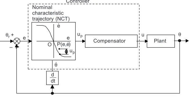
The structure of the NCTF control system is shown in Figure 1. The NCTF controller consists of a nominal characteristic trajectory (NCT) and a compensator. The NCTF controller works under the following two assumptions:
(i) A DC or an AC servomotor is used as an actuator of the plant.
(ii) PTP positioning systems are chosen, so θr is constant and θ ≡r 0.
Figure 2 shows an example of a plant motion controlled by the NCTF controller. The motion comprises of two phases. The first one is the reaching phase and the second is the following phase. In the reaching phase, the compensator forces the plant motion to reach the NCT as fast as possible. However, in the following phase the compensator controls the plant motion so as to follow the NCT and end at the origin. The plant motion stops at the origin, which represents the end of the positioning motion. Thus, in the NCTF control system, the NCT governs the positioning response performance.
Figure 2 NCT and plant motion
Error rate e
.
Plant motion NCT
RP: Reaching phase
O
FP RP
Error e
FP: Following phase
Figure 1 NCTF control system
Controller Nominal
characteristic trajectory (NCT)
O e e.
u θ
Plant Compensator
up P(e,e.)
θr +
d dt e
–
up
The NCTF controller is designed based on a simple open-loop experiment of the plant as follows:
(i) Open-loop-drive the plant with stepwise inputs and measure the displacement
and velocity responses of the plant.
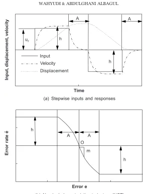
Figure 3(a) shows the stepwise inputs, and the velocity and displacement responses
due to the stepwise inputs. In this paper, the rated input to the actuator ur is used
as the height of the stepwise inputs.
(ii) Construct the NCT by using the plant responses.
The velocity and displacement responses are used to determine the NCT. Since the main objective of PTP system is to stop the plant at a certain position, a
Figure 3 NCT determination
A A
Input, displacement, velocity
ur h
h Input
Time
(a) Stepwise inputs and responses
h
A A
O
m
h
Error e
(b) Nominal characteristics trajectory (NCT)
Error rate e
.
deceleration process is used, see curve A, Figure 3(a). The h in Figure 3 represents the maximum velocity. From the curve in area A and h in Figure 3(a), the NCT in Figure 3(b) is determined. Since the NCT is constructed based on the actual responses of the plant, it includes nonlinearity effects such as friction and saturation. The important NCT information which will be used to design the compensator are NCT inclination m near the origin and maximum error rate of h. In this case, from the relationship between plant dynamics of Equation(1) and Figure 3(b), it is clear that the inclination near origin, m and the maximum error rate, h relate with parameters of the plant as follows [12,15]:
= − r h K u (1) m
α = − (2)
(iii) Design the compensator based on the NCT information.
Here, the following PI compensator is adopted due to its simplicity:
= p p + i
∫
pu K u K u dt (3)
where Kp and Ki are proportional and integral gains respectively. Using the PI
compensator parameters, Kp and Ki, and the NCT characteristic near the origin (see
Figure 3(b)), the transfer function of the closed-loop positioning system controlled by the NCTF controller can be approximated as follows [11-15]:
( )
( ) ( ) ( ) ( )
Θ = =
Θ 1 2
r
s
G s G s G s
s (4) where ( ) 1 G s s α =
+ α (5a)
( ) n 2n
2 2 2
n n 2 G s s 2 ζω + ω =
+ ζω + ω (5b)
n p 2 K K ζω = α (5c) 2 n i K K ω = α (5d)
where K and α are positive constants which relate to the plant dynamics. Meanwhile,
large enough, G(s) becomes nearly equal to G1(s), which represent the condition when the plant motion follows the NCT as the objective of the NCTF control system.
Moreover, large ζ and ωn also make the closed-loop system robust to friction or inertia
variation of the plant in continuous systems [9]. Finally, by using ζ and ωn as design
parameters and considering Equations (2) and (3), the PI compensator parameters are designed as follows:
n r
p 2 u
K
mh
ζω
= (6)
2 n r i
u K
mh
ω
= (7)
Here, ωn and ζ are design parameters which should be decided by the designer.
Generally speaking, a higher ω and a larger ζ are preferable in the design of PI
compensator parameters. However, physical constraint of the motor driver and digital implementation of the NCTF controller limits the design parameters to maintain the closed-loop stability as follows [12]:
R n
KS h
α
ω ≤ (8)
n 2 3T
ζω ≤ (9)
where SR and T are motor driver slew rate and sampling time. Detailed discussion on
the theoretical background of the NCTF control system can be seen in [12, 14, 15]. Due to the fact that the NCT and the compensator are constructed from a simple open-loop experiment of the plant, the exact model including the friction characteristic and the identification task of the plant parameters are not required to design the NCTF controller. Therefore, the controller design is simple and easy to implement in practical situation.
2.2 Fuzzy Anti-Windup Scheme
As the NCTF controller uses PI compensator to force plant motion so that it follows the NCT, the integrator windup up may occur in connection with large position reference. As discussed in reference [15], in the case of no parameter variations, there is no significant integrator windup due to the effect of the saturation. The effect of the saturation is successfully compensated by using NCTF controller. However, the integrator windup becomes a problem when the parameters vary [15].
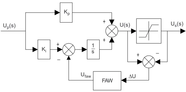
compensator is proposed to be used instead of a pure PI compensator. Here, the fuzzy anti-windup is designed based on the Mamdani fuzzy system. The structure of the anti-windup PI compensator is illustrated in Figure 4, where FAW is the proposed fuzzy anti-windup. By using the proposed anti-windup PI compensator, it is expected that once PI compensator output U(s) exceeds the actuator limits, the FAW will generate a signal to reduce the effect of the integrator windup.
Figure 4 Proposed anti-windup PI compensator
+ +
+ + Up(s)
– U(s)
Kp
Ki
Us(s)
Ufaw ∆U FAW
–
1 s
The fuzzy anti-windup, as shown in Figure 5, consists of three conceptual components: a rule base which contains set of fuzzy rule, a data base which defines the membership function used in the fuzzy rules, and a reasoning mechanism which performs the inference procedure. Furthermore, since the input as well as the output of the FAW are
. . .
Figure 5 Fuzzy anti-windup scheme
Rule r
Defuzzification Aggregator
Antecedent I Fuzzification
Rule 2
Antecedent 2 Rule 1
Antecedent 1 Consequant 1
Consequant 2
crisp values, fuzzification and defuzzification are also included in the FAW. Fuzzification is a mapping from the crisp input (observed numerical input) into the fuzzy sets defined in the corresponding universe of discourse, while defuzzification is a method to extract a crisp output value that best represents the fuzzy output.
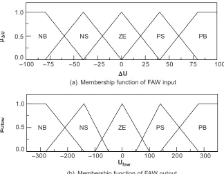
The first element of the fuzzy anti-windup is the fuzzy interface which is used to convert crisp input of the control output into linguistic variables. To map the crisp inputs into related linguistic fuzzy sets, associated membership functions have to be constructed. Figure 6 shows the membership functions of the FAW. As shown in Figure 6, each of the input and output of the FAW consists of five fuzzy sets (linguistic variables), namely Negative Big (NB), Negative Small (NS), Zero (ZE), Positive Small (PS) and Positive Big (PB). The linguistic variables NS, ZE, and PS use triangle membership function, while NB and PB adopt trapezoidal membership function.
Figure 6 Membership function of the FAW input and output
–100 –75
∆∆∆∆∆U
(a) Membership function of FAW input
µµµµµ∆∆∆∆∆
U
100 75
50 25
0 –25 –50
(b) Membership function of FAW output
Ufaw
0.0 0.5 1.0
NB NS ZE PS PB
–300 –200
µµµµµUfaw
300 200
100 0
–100 0.0
0.5 1.0
NB NS ZE PS PB
Fuzzy rule base is the second element of the FAW. The fuzzy rule-base is composed of IF-THEN rules like:
IF antecedent 1 THEN Consequent 1 (10)
The following fuzzy rules are derived to reduce the effect of the integrator windup:
(i) IF ∆U is NB THEN Ufaw is PB
(iii) IF ∆U is ZE THEN Ufaw is ZE
(iv) IF ∆U is PS THEN Ufaw is NS
(v) IF ∆U is PB THEN Ufaw is NB
Furthermore, the fuzzy inference engine and the defuzzifier are used to carry out all
the fuzzy operations and hence determine the FAW output Ufaw on the activated rules
along with the membership degrees of the associated fuzzy inputs. In this paper, Mamdani fuzzy inference engine is used to determine the FAW output. The Mamdani inference engine used in this paper was based on Mamdani implication (Min operation) and disjunctive aggregator (Max operator), while the FAW output is converted into crisp output based on the centroid method [16].
3.0 CONTROLLER DESIGN
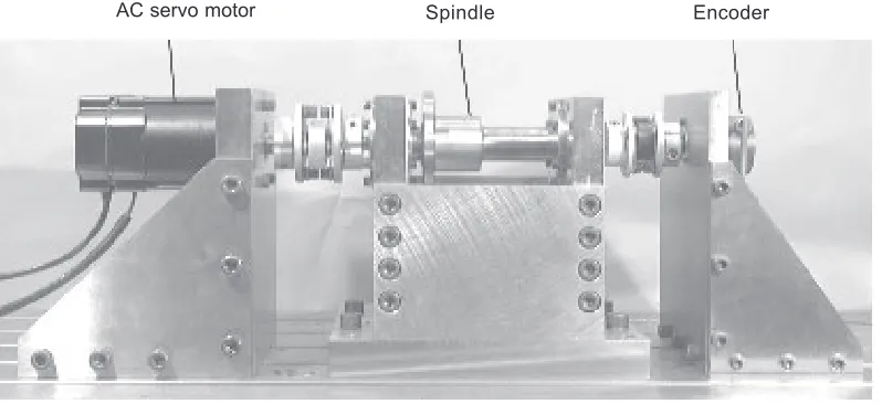
3.1 Plant Description
Encoder Spindle
Figure 7 Experimental rotary positioning system
AC servo motor
3.2 Controller Design
First, the NCTF controller was designed based on the normal plant. Figure 9 shows the NCT as a result of a simulated experiment. With reference to Figure 9, the inclination m and maximum error rate h of the NCT are 67.4 rad and 240 rad/s respectively. The compensator parameters are designed by using h and m of the NCT. For the PI
compensator, design parameters ζ and ωn are chosen as 13 and 29 respectively [15].
Table 2 shows the values of the compensator parameters calculated using Equations (6) and (7).
The performances of the positioning system using the NCTF controllers are also compared to that of a PID controller with the following transfer function:
= + + 1 p D K
U(s) K K s E(s)
s (11)
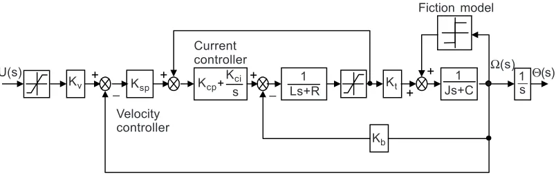
Table 1 Parameters of the plant
Parameter Value
Inertia load, J 1.17 × 10⁻³
kgm2
Motor resistance, R 1.2 Ω
Motor inductance, L 8.7 mH
Motor torque constant, Kt 0.57 Nm/A Back-Emf constant, Kb 0.57 Vs/rad Viscous friction, C 1.67 × 10⁻³
Nms/rad Frictional torque, tf 0.215 Nm
Proportional current gain, Kcp 26.2 V/A Integral current gain, Kci 3.62 × 10³ V/As Proportional velocity gain, Ksp 8.60 × 10⁻² As/rad Input voltage range, ur ± 6 Volt
Figure 8 Detailed model of rotary positioning system -+ + + + + + -Kcp U(s)
Kv Ksp – Kb Kci s – Current controller – 1
Ls+R Kt
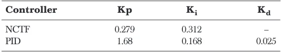
where Kp, Ki and Kd are proportional, integral and derivative gains respectively. The PID controller was designed so that it has a similar bandwidth with the NCTF control system [15]. In this paper, the PID controller tuned with Ziegler-Nichols rule is not discussed again since it gives a bad robustness to parameter variations [15]. The PID controller parameters are also shown in Table 2.
Figure 9 Nominal characteristic trajectory (NCT)
200
–15
Error rate rad/s
0
h = –240 m = –67.4
–200 –100 0 100
–10 –5 5 10 15
Error rad
4.0 RESULTS AND DISCUSSIONS
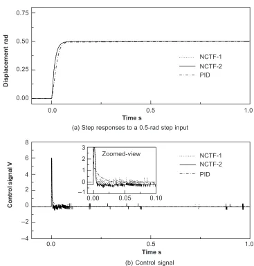
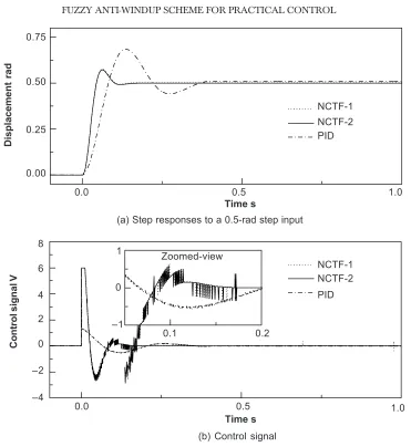
In this section, the performance of the positioning system using the NCTF (NCTF-2) controller with the anti-windup PI compensator was compared to that of a normal NCTF (NCTF-1) and PID controllers. Figure 10 shows the step responses to a 0.5-rad step input when the controllers were used to control normal plant and their positioning performances are summarized in Table 3. The positioning performance was evaluated based on maximum overshoot and 2% settling time. As shown in Figure 10(b), the 0.5-rad step input does not cause the saturation of the control signal. Here, it is clear that all of the controllers produce similar responses due to a similar bandwidth. Hence in terms of overshoot and settling time, all of the controllers gave a similar performance. Moreover, in order to evaluate the robustness of the control system to inertia variation, all of the controllers were implemented using increased inertia plant. Figure 11 shows the step responses to a 0.5-rad step input when all of the controllers are implemented for controlling increased inertia plant. Table 3 shows the positioning performance
Table 2 NCTF compensator and PID controller parameters
Controller Kp Ki Kd
NCTF 0.279 0.312 –
resulting from all of the controllers. Figure 11 and Table 3 show that both NCTF controllers give similar overshoot and settling time, while the PID controller results in the largest overshoot and longest settling time. Hence it can be concluded that both NCTF controllers give a better robustness to inertia variation than the PID controller. Both NCTF controllers give similar results because there is no significant saturation of the actuator as shown Figure 11(b). The result confirms that the use of anti-windup PI compensator does not affect the positioning performance, when there is no saturation of the actuator.
Figure 10 Comparison of response to a 0.5-rad step input, normal plant
Displacement rad
NCTF-1 NCTF-2 PID
Time s
(a) Step responses to a 0.5-rad step input
Zoomed-view NCTF-1 3
Control signal V
Time s
(b) Control signal 0.75
0.50
0.25
0.00
0.0 0.5 1.0
NCTF-2 PID 8
6
4
0.0 0.5 1.0
0.05 0.00
2
1
0 –1 2
0
–2
0.10
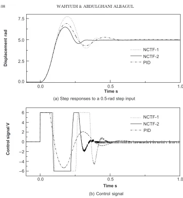
Next, simulation was done for a larger step input so that the actuator saturates. Figure 12 shows the step responses to a 5-rad step input when all of the controllers are implemented for controlling increased inertia plant. Table 4 shows the positioning performance resulting from all of the controllers. The saturation of the actuator occurs as shown in Figure 12(b). The saturation of the actuator causes an integrator windup when the positioning system is controlled by both NCTF-1 and PID controller. However, Figure 12(a) and Table 4 show that the performance of the positioning system with NCTF-1 is worse than that with PID controller since the NCTF-1 produces a larger overshoot than the PID controller. Hence the NCTF-1 becomes less robust to inertia variations when the saturation occurs compared to that of the PID controller. On the other hand, NCTF-2 which uses the anti-windup PI compensator can
Figure 11 Comparison of response to a 0.5-rad step input, increased inertia plant
Displacement rad
NCTF-1 NCTF-2 PID
Time s
(a) Step responses to a 0.5-rad step input
Zoomed-view
NCTF-1
Control signal V
Time s
(b) Control signal 0.75
0.50
0.25
0.00
0.0 0.5 1.0
NCTF-2 PID 8
6
4
0.0 0.5 1.0
0.2 0.1
1
0
–1 2
0
–2
Figure 12 Comparison of response to a 5-rad step input, increased inertia plant
Displacement rad
NCTF-1 NCTF-2 PID
Time s
(a) Step responses to a 0.5-rad step input
NCTF-1
Control signal V
Time s
(b) Control signal 7.5
5.0
2.5
0.0
0.0 0.5 1.0
NCTF-2 PID 6
4
0.0 0.5 1.0
2
0
–2
–4
–6
Table 3 Performance comparison, 0.5-rad step input
Plant Controller Settling time (sec) Overshoot (%)
Normal NCTF-1 0.059 0
NCTF-2 0.060 0
PID 0.072 0
Increased inertia NCTF-1 0.097 15.2
NCTF-2 0.095 14.8
successfully compensate the effect of integrator windup due to actuator saturation. As the results show, the improved NCTF controller (NCTF-2) gives a smaller overshoot and a shorter settling time than the other controllers. Hence it can be concluded that the improved NCTF controller which uses anti-windup PI compensator can maintain the robustness to parameter variations even if the actuator of the plant saturates.
Another simulation was done to compare the improved NCTF controller with anti-windup PID controller. For this purpose, a conventional anti-anti-windup discussed in reference [17] is adopted. The anti-windup PID controller has the following transfer function [17]:
[
]
= + + − −
1
p D s
K KT
U(s) K K s E(s) U(s) U (s)
s s (12)
where KT, U(s) and Us(s) are tracking gain, unsaturated and saturated control outputs
respectively. In this paper, two tracking gains, KT, were used. The first anti-windup
PID controller (PID-1) uses a KT = KI, while the second anti-windup PID controller
(PID-2) uses a tracking gain ratio KT = 12 KI. Figure 13 shows the step responses to a
5-rad step input when all of the controllers are implemented for controlling increased inertia plant. Table 5 shows the positioning performance resulting from all of the controllers. Figure 13 and Table 5 show that the use of anti-windup PID controllers improves the robustness to inertia variation compared with the normal PID controller shown in Table 4. However, as shown in Figure 13 and Table 5, they still give a larger overshoot and longer settling time than the improved NCTF controller. Therefore, they are still less robust to inertia variation compared with the improved NCTF controller. Hence it can be concluded that the improved NCTF controller is more robust than the anti-windup PID controllers.
Table 4 Performance comparison, 5-rad step input
Plant Controller Settling time (sec) Overshoot (%)
Increased inertia NCTF-1 0.420 54.3
NCTF-2 0.312 29.7
PID 0.520 38.2
Table 5 Anti-windup performance comparison, 5-rad step input
Plant Controller Settling time (sec) Overshoot (%)
Increased inertia NCTF-2 0.312 29.7
PID-1 0.514 37.4
5.0 CONCLUSIONS
This paper has documented the improvement of the NCTF controller to overcome the effects of integrator windup due to actuator saturation. A fuzzy anti-windup PI compensator was used as compensator for the NCTF controller instead of a conventional PI compensator. Through simulation using dynamic model of a rotary positioning system, the effectiveness of the NCTF controller with anti-windup PI compensator was evaluated. The improved NCTF controller was compared with the normal NCTF, PID and anti-windup PID controllers. The results confirm that the NCTF controller with the fuzzy anti-windup PI compensator is better than the other controllers. The use
Figure 13 Comparison of response to a 5-rad step input, increased inertia plant
Displacement rad
PID-1 NCTF-2 PID-2
Time s
(a) Step responses to a 0.5-rad step input
PID-1
Control signal V
Time s
(b) Control signal 7.5
5.0
2.5
0.0
0.0 0.5 1.0
NCTF-2 PID-2 6
4
0.0 0.5 1.0
2
0
–2
–4
of the fuzzy anti-windup PI compensator is more effective to overcome the problem due to integrator windup, compared to that of the other controllers. Moreover, the simulation results also confirm that the NCTF controller with an anti-windup PI compensator, which is designed based on a simple open loop experiment, gave the best positioning performance as well as performance robustness to parameter variations. Hence the ease of NCTF controller design process and a better performance and robustness compared to the PID controllers become the major advantage of the NCTF controller in the practical applications.
ACKNOWLEDGEMENTS
The authors wish to acknowledge that this work has been supported by long-term research grant under the Research Center of International Islamic University, Malaysia.
REFERENCES
[1] Umeno, K., T. Kanoko, and Y. Hori. 1993. Robust Servo System Design with Two Degree of Freedom and its Applications to Novel Motion Control of Robot Manipulators. IEEE Trans. on Industrial Electronics. 40(5): 473-485.
[2] Endo, S., H. Kobayashi, C. J. Kempf, S. Kobayashi, M. Tomizuka, and Y. Hori. 1996. Robust Digital Tracking Controller Design for High-speed Positioning Systems. Control Engineering Practice. 4(4): 527-536. [3] Tomizuka M. 1996. Robust Digital Motion Controllers for Mechanical Systems. Robotics and Autonomous
Systems. 19: 143-149.
[4] Kempf, C., and S. Kobayashi. 1999. Disturbance Observer and Feedforward Design for a High-speed Direct-drive Positioning Table. IEEE Trans. on Control Systems Technology. 7(5): 513-526.
[5] Wu, S., and J. Fu. 1998. Time-optimal Control of Servo Systems Using PD Algorithms. JSME International Journal: Series C. 41(3): 384-390.
[6] Park, M. H., and C. Y. Won. 1991. Time Optimal Control for Induction Motor Servo System. IEEE Trans. on Power Electronics. 6(3): 514-524.
[7] Workman, M. L., R. L. Kosut, and G. F. Franklin. 1987. Adaptive Proximate Time-optimal Servo Mechanisms: Continuous Time Case. In proceedings of the American Control Conference. Minneapolis, USA. 589-594. [8] Kempf, C. J. 1996. Step and Settle Positioning Algorithm for Electro-mechanical System with Damping. In
proceedings of the 4th International Workshop on Advanced Motion Control. Tsukuba, Japan. 47-52. [9] Sankaranarayanan, S., and F. Khorrami. 1997. Adaptive Variable Structure Control and Applications to
Friction Compensations. In proceedings of the 36th IEEE Conference on Decision & Control. San Diego, USA. 4159-4164.
[10] Fujimoto, Y., and A. Kawamura. 1995. Robust Servo-system Based on Two-degree-of-freedom Control with Sliding Mode. IEEE Trans. on Industrial Electronics. 42(3): 272-280.
[11] Wahyudi. 2002. New Practical Control of PTP Positioning Systems. Ph.D. Diss. Dept. of Precision Machinery Systems, Tokyo Institute of Technology.
[12] Wahyudi, K. Sato, and A. Shimokohbe. 2001. Robustness Evaluation of New Practical Control Method for PTP Positioning Systems. In proceedings of 2001 IEEE/ASME International Conference on Advanced Intelligent Mechatronics. Como, Italy. 843-848.
[13] Wahyudi, K. Sato, and A. Shimokohbe. 2001. New Practical Control Method for PTP Positioning Systems: Robustness Evaluation. In proceedings of 10th International Conference on Precision Engineering. Yokohama, Japan. 774-778.
[15] Wahyudi, K. Sato, and A. Shimokohbe. 2003. Characteristics of Practical Control for Point-to-point (PTP) Positioning Systems: Effect of Design Parameters and Actuator Saturation on Positioning Performance.
Precision Engineering. 27: 157-169.
[16] Ross, T. J. 1997. Fuzzy Logic with Engineering Applications. New York: McGraw-Hill.