Characteristics of Packings for Stuffing Boxes
for the Proof of Strength, Function and Tightness of Valves
Jaroslav Bartonicek 1) , Rolf Hahn 2), Hans Kockelmann 2), Eberhard Roos 2) and Friedrich Schöckle 3) 1) Gemeinschaftskernkraftwerk Neckar GmbH, Neckarwestheim, Germany
2) Staatliche Materialprüfungsanstalt (MPA) University of Stuttgart, Stuttgart, Germany 3)
AMTEC, Messtechnischer Service GmbH, Lauffen, Germany
ABSTRACT
The operational safety of whole industrial plants is depending amongst others on the reliable function and tightness of valves. Therefore the sealing element stuffing box with packing is of great importance. For a suitable design of valves distinct characteristics of packings for stuffing boxes are required, describing the deformation, relaxation, friction, and tightness behaviour. These characteristics are defined and the testing procedures for their experimental determination are developed. Exemplary results lighten the typical and different performance of varied packing materials. Extensive characterisation of the materials mostly in use is subject of present testing programmes. Further on some ideas of topics for future research work are presented.
INTRODUCTION
Valves are important components in view of the safety and functional performance of whole industrial plants. The sealing element - stuffing box with packing – is decisive for the tightness and the function of the valve. The axial gland load on the packing results in a radial stress (between packing and stem, as well as between packing and housing), which is required for tightness. Therefore the axial load should be high enough for tightness in every service condition. On the other hand the movability of the stem is a pre-requisite for the function of the valve; in order to minimise the frictional force between stem and packing for sufficient movability the gland load must be not too high. Both targets - high tightness and low frictional stem force – are conflicting requirements for the gland load.
For safety related valves a proof of frictional stem force is often required. Further on an increasing demand arises for tightness proof in view of a reduction of environmental pollution and medium loss. These are some reasons for the growing interest in the characterisation of packings for stuffing boxes. Another reason is the need for the replacement of asbestos containing packing materials, which were in use for long time with excellent service experience. This does not yet yield for asbestos substitutes. In addition raised temperatures for improved efficiency of power plants are a new challenge for the new asbestos-free packings.
In this paper the characteristics of packings required for the selection of suitable packings, the determination of the assembly gland forces, the calculation of the stem frictional force, and the tightness proof are discussed first. Thereafter testing procedures and equipments for the determination of these characteristics are described. In addition some typical results for different packing materials are presented.
CHARACTERISTICS OF PACKINGS FOR STUFFING BOXES
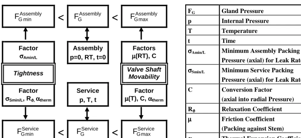
The concept for tightness and function proof of valves with stuffing box sealing elements is shown in Fig. 1. The characteristics of the packing implemented in this concept are discussed below.
The frictional stem force FS is given by the following analytical relation [1], [2], [3], [4]:
ú ú û ù ê ê ë é ÷÷ ø ö çç è æ − µ − − + = i a i o i G S r r L C 2 exp 1 r r r F F (1)
The gland load FG is given by:
(
o2 i2)
axG r r
F =π − σ (2)
Therefore the geometrical dimensions of the packing (outer and inner diameter ro and ri; length L in the compressed stage), the packing characteristics (friction coefficient µ; conversion coefficient C, describing the ratio of resulting radial and inducing axial stress), and the axial stress on the upper packing ring (σax) must be known.
SMiRT 16, Washington DC, August 2001 Paper # 1731
Fig. 1: Concept for tightness and function proof of stuffing box sealing elements
For tightness the packing has to be compressed in order to close inner leakage channels in the packing and to bridge existing gaps between packing and stem or housing. This asks for the packing characteristic σAmin, the minimum assembly packing stress. For tightness in all subsequent service conditions a minimum service packing stress σSmin is required.
With long-term service under the influence of temperature and time creep-relaxation will take place due to irreversible plastic creep compression set of the packing, resulting in a loss of packing stress. This behaviour is considered by means of the relaxation factor Rϑ (for temperature ϑ):
Rϑ =
Assembly rad
Service rad
Assembly ax
Service ax
σ σ ≈ σ
σ
(3)
In conclusion the following characteristics of packings have to be defined describing • the deformation behaviour (compression set, conversion factor C, relaxation factor Rϑ)
• the tightness behaviour (minimum assembly (σAmin) and service (σSmin) packing stress for distinct leakage rate or tightness class)
• the frictional behaviour (friction coefficient µ) These characteristics are summarised in Table 1.
In addition the long-term chemical resistance for the given service conditions (medium, temperature, ...) has to be regarded.
Due to the lack of standardisation of the testing procedures for packings the data basis is poor. Deformation and friction characteristics can be found in the literature and prospectus of the manufacturers, but the values are often questionable and not comparable, because the testing methods are unknown or different. Hardly any data are available for the tightness and relaxation behaviour. This fact complicates the design of valves and impedes the development of maintenance procedures.
TESTING TECHNIQUES AND RESULTS
The characteristics of packings are determined in 4 different types of tests, Table 1. The testing technique was discussed in detail in [5]. Some new results are presented in the following.
Assembly min G
F
<<<<
F
GAssembly<<<<
F
GAssemblymaxFactor
σσσσAmin/L
Assembly p=0, RT, t=0
Factors
µµµµ(RT), C
Tightness Valve Shaft
Movability
Factor
σσσσSmin/L, Rϑϑϑϑ, ααααtherm
Service p, T, t
Factor
µµµµ(T), C, ααααtherm
Service min G
F
<<<<
F
GService<<<<
F
GServicemaxFG Gland Pressure
p Internal Pressure
T Temperature
t Time
σσσσAmin/L Minimum Assembly Packing
Pressure (axial) for Leak Rate L σσσσSmin/L Minimum Service Packing
Pressure (axial) for Leak Rate L
C Conversion Factor
(axial into radial Pressure)
Rϑϑϑϑ Relaxation Coefficient µµµµ Friction Coefficient
(Packing against Stem) α
αα
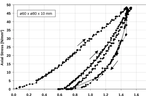
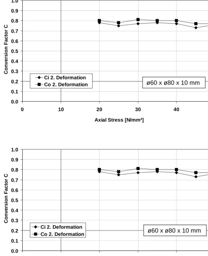
conversion factor increases remarkably (fig. 3 top); after unloading and re-loading it is approximately independent of the stress (fig. 3 bottom). Varied types of packing materials show typical differences in the deformation behaviour .
Table 1. Characteristics and testing procedures for packings for stuffing boxes
Characteristic Symbol Purpose, Description Testing Procedure
Compression set Capability for fulfillment of existing gaps between packing and housing during assembly
Compression test
Conversion factor C Conversion of axial stress (gland force) into radial stress (for tightness)
Compression test
Relaxation factor Rϑ Relaxation of gland force Relaxation test Minimum assembly
stress
σAmin/L1) Adaptation of the packing to the surface, closure of inner leakage channels
Leakage test
Minimum service stress σSmin/L1) Tightness in all service conditions Leakage test Friction coefficient µ Friction between stem and packing, friction force Friction test 1)
Subscript L refers to a distinct leakage rate or tightness class
0
5
10
15
20
25
30
35
40
45
50
0.0
0.2
0.4
0.6
0.8
1.0
1.2
1.4
1.6
1.8
Deformation [mm]
Axial S
tress [N/mm²]
0.0 0.1 0.2 0.3 0.4 0.5 0.6 0.7 0.8 0.9 1.0
0 10 20 30 40 50
Axial Stress [N/mm²]
C
o
n
ver
si
o
n
F
acto
r C
Ci 2. Deformation Co 2. Deformation
0.0 0.1 0.2 0.3 0.4 0.5 0.6 0.7 0.8 0.9 1.0
0 10 20 30 40 50
Axial Stress [N/mm²]
C
o
n
ver
si
o
n
F
acto
r C
Ci 2. Deformation Co 2. Deformation
ø60 x ø80 x 10 mm
Relaxation Test
Fig. 4 shows the creep-relaxation at 200 °C of a 6 ring yarn packing made from PTFE-fibres without basic rings. In Fig. 5 the relaxation with time of a packing with 6 rings of flexible graphite is shown for varied temperature. At 300°C and higher temperature remarkable relaxation takes place due to stress re-distribution in the packing, wear and graphite degradation.
0 5 10 15 20 25 30 35 40 45 50
0 100 200 300 400 500 600 700
Time [ h ]
Ax
ia
l S
tre
s
s
[
N/m
m
²]
Fig. 4: Relaxation of a packing containing 6 rings of PTFE fibre (200 °C)
0
5
10
15
20
25
30
35
40
45
0
500
1000
1500
2000
2500
3000
3500
4000
Time [h]
Axi
a
l S
tr
ess [N/
m
m
²]
400 °C300 °C
150 °C
ø40 x ø56 x 8 mm
Friction Test
Investigations on single packing rings are most suitable for the determination of the friction coefficients, because the effect of the stem movement on the axial and radial packing stress is low. The effective friction force is determined with real packings containing several rings; so the formula for the calculation of the friction force can be examined and verified. Generally the friction coefficient is reduced with increasing packing stress and temperature. Varied packing materials show clearly different friction behaviour, Fig. 6.
0.000 0.025 0.050 0.075 0.100 0.125 0.150 0.175 0.200 0.225 0.250
0 10 20 30 40 50 60
Axial Stress [N/mm²]
Friction Coefficient
Compressed Flexible Graphite Flexible Graphite Yarn
PTFE Yarn with incorporated Flexible Graphite PTFE Yarn
Fig. 6: Friction coefficient between stem and packing as a function of the axial stress for different packing materials at room temperature (stem surface roughness Rz = 2,3 µm)
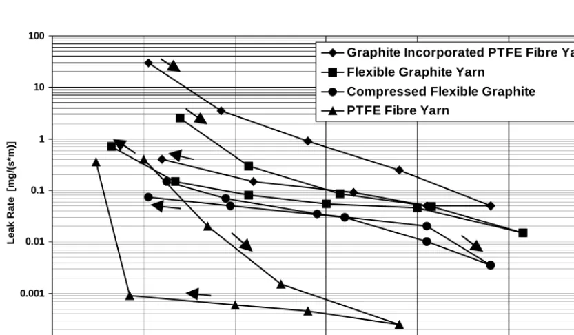
0.001 0.01 0.1 1 10 100
L
eak R
ate [m
g
/(s*
m
)]
Graphite Incorporated PTFE Fibre Yarn Flexible Graphite Yarn
Leakage Test
As an example Fig. 7 shows the correlation between the leakage rate (for 40 bar Nitrogen) and the axial stress for packings with 2 rings of different packing material. From this graph the minimum assembly stress σAmin/L for distinct leakage rate levels or tightness classes L can be delineated. Here e.g. for tightness class 1 mg / (s m) a value of 28 N/mm2 is required for σAmin/1.0 and graphite incorporated PTFE fibre yarn; after pre-deformation with 48 N/mm2 the required minimum service stress σSmin/L for this tightness class amounts only to less than about 10 N/mm2. This clearly shows the advantage of high pre-stressing in view of tightness. The development of the leakage rate with cyclic stem movement is shown in Fig. 8 for packings made from 4 rings of flexible graphite. After about 2000 strokes the leakage rate increases remarkably.
0.1 1 10 100 1000 10000
L1 L2 L3 L4 L5 L6 L7 L8 L9 L12 L16
L
eak R
ate [mg
/(s*
m)]
Heating from RT to 300°C
Total Number N of Stem Strokes: 50
29,5 N/mm² 29 N/mm² 25 N/mm² 25 N/mm² 24 N/mm² 24 N/mm² 23 N/mm² 23 N/mm² 23 N/mm² 23 N/mm² 17 N/mm²
N: 150
N: 400
N: 1400
N: 2400
N: 2650
N: 3150
N: 6000
N: 8000
Number of Leakage Measurement
RT
Fig. 8: Effect of cyclic strem strokes on the tightness of a packing with 4 rings of flexible graphite (160 bar; Nitrogen; 300 °C)
SUMMARY AND OUTLOOK
For the design of valves (function and tightness proof) with stuffing boxes as sealing elements specific characteristics of the stuffing box packings are required, describing the deformation, relaxation, friction and tightness behaviour. These characteristics are defined and discussed. The testing procedures for their reliable and reproducible experimental determination were discussed elsewhere. A few examples of testing results are presented showing some aspects of the typical behaviour of varied packing materials in use.
Subject of running research work is the extensive characterisation of the following packing materials: • compressed flexible graphite
• flexible graphite yarn • PTFE yarn
• PTFE yarn with incorporated flexible graphite fibres and some specially designed integral packings.
Topics of planned future work are amongst others
• the validation of the developed testing procedures by means of long-term tests and tests on real valves, • the variation of the medium in the leakage test (water, steam), and
REFERENCES
1. Thomson, J.L., Packed Glands for High Pressures: an Analysis of Fundamentales; Combustion, Vol. 29, 1958, pp. 38-51 2. Denny, D.F. and Turnbull, D.E., Sealing Characteristics of Stuffing-Box Seals for rotationg Shafts; Proc. Justn. Engrs.,
London, Vol. 174, 1960, pp. 271-291
3. KWU, KWU-Richtlinie zum rechnerischen Festigkeitsnachweis im Kraftfluß liegender Bauteile von Armaturen; V 29/82/1029 b vom 26.08.1983
4. TÜV-Leitstelle Kerntechnik bei dem VdTÜV, Berechnung sicherheitstechnisch wichtiger Schieber und Ventile hinsichtlich Funktion und Auswirkungen von Stellkräften, 08.10.1993