!
ABSTRACT
IYER HARINI RAMACHANDRAN. Automation of Scientific Workflow Construction using Templates and Patterns. (Under the direction of Dr. Mladen Vouk.)
Automation of scientific simulation, experimentation and analysis processes is becoming a necessary part of scientific problem solving. Workflows that implement such processes need to work efficiently with large amounts of data, and they need to automate what could normally be a very time-consuming and error-prone task. Design and development of workflows requires both expertise in the scientific domain as well as an understanding of, and facility with, a workflow implementation language(s) and engine. This work presents a study based on a group of workflows developed at Oak Ridge National Laboratory (ORNL) called monitoring workflows. It discusses an approach to monitoring workflow development based on the use of software engineering pattern and template principles. This work examines the similarities amongst the monitoring workflows, and it crafts templates based on the patterns followed by them. It involves the use of relatively high-level parameterized components that can then be composed into more complex entities. A ”fill in the blank” model for building monitoring workflows using templates and patterns is developed and prototyped. It is shown that complex workflows can be built automatically using templates, and that this does reduce information technology overhead for construction of this type of workflows.
!
!
!
!
Automation of Scientific Workflow Construction using Templates and Patterns
by
Harini Ramachandran Iyer
A thesis submitted to the Graduate Faculty of North Carolina State University
in partial fulfillment of the requirements for the Degree of
Master of Science
Computer Science
Raleigh, North Carolina
2010
APPROVED BY:
_______________________________ ______________________________
Dr. Munindar Singh Dr. Rada Chirkova
________________________________ Dr. Mladen A. Vouk
! ""!
DEDICATION
To
! """!
BIOGRAPHY
Harini Iyer was born in Ahmedabad, India. She finished her schooling in Ahmedabad and
received the Bachelor degree in Computer Science from Nirma University, Ahmedabad. She
worked for Cognizant Technology Solutions, Pune, for a year as a part of the development
group for the launch of eBay.in. She joined North Carolina State University for the Graduate
Masters Programme in Computer Science in Fall 2008 and joined the SDM group in Spring
! "#!
ACKNOWLEDGMENTS
I would like to express my sincere gratitude towards my thesis advisor, Dr. Mladen Vouk for
his constant guidance, support and encouragement. I would also like to thank Dr. Rada
Chirkova for serving on my thesis committee. I am highly obliged to Dr. Munindar Singh for
serving on my thesis committee, for his time, for his invaluable suggestions and for guiding
me at various stages of my research.
I would like to use this opportunity and thank my colleagues at the SDM center, Norbert and
Ustun, and my colleague at NCSU, Pierre, for their constant help and support throughout my
research. Special thanks to Norbert, an excellent person to work with, for being so patient
with me and answering all my questions.
! "#!
TABLE OF CONTENTS
LIST OF FIGURES………...vii!
LIST OF TABLES………viii!
Chapter 1 - Introduction……….1!
Chapter 2 - Background………..5!
2.1 Definitions ………5!
2.2 Workflows. ………..6!
2.2.1 Architecture of a Business Workflow………7!
Chapter 3 - Scientific Workflows……….10!
3.1 Architecture ... 10!
3.2 Lifecycle of a Scientific Workflow ... 13!
3.3 Workflow Users... 16!
3.4 Benefits... 17!
3.5 Types of Scientific Workflows ... 18!
3.6 Business Workflows vs. Scientific Workflows ... 20!
Chapter 4 - Scientific Data Management Center………24!
4.1 Scientific Process Automation (SPA) ... 26!
4.1.1 Framework for Integrated End-to-End SDM Technologies and Applications [FIESTA].. 26!
4.1.2 Ptolemy II ... 28!
4.1.3 Kepler ... 29!
4.1.3.1 Architecture of Kepler System ... 30!
! #!
4.1.4 Outreach and growth of SPA ... 35!
4.2 Case Study Scientific Workflows... 39!
4.2.1 Automation Tasks of the Monitoring Workflows ... 40!
4.2.2 Features of a Monitoring Workflow ... 41!
4.2.3 XGC Simulation Code... 42!
4.2.4 GEM Simulation Code ... 43!
4.2.5 Pixie3D Simulation Code ... 43!
4.2.6 Analysis of the Monitoring Workflows... 43!
Chapter 5 - Workflow Templates and Patterns………..45!
5.1 Basic Workflow Patterns... 46!
5.2 CPES Generic Template – ProcessFileRT actor ... 48!
5.3 Our approach to templates... 50!
5.4 Templates for the Workflow Generator Wizard ... 51!
5.4.1 Preparation Steps ... 52!
5.4.2 Post-processing Steps ... 53!
5.4.3 Performance Monitoring Steps ... 54!
5.4.4 Processing Steps (Auto-generated Template)... 55!
5.4.5 Miscellaneous Templates/Generic Actors ... 57!
Chapter 6 - Workflow Generator Wizard………...59!
6.1 An XML Representation of a Workflow... 60!
6.2 Architecture ... 62!
6.3 Implementation ... 63!
6.3.1 Web Form ... 64!
6.3.2 Library ... 66!
6.3.3 Generator ... 66!
6.3.4 Performance Analysis and Testing ... 67!
6.3.4 Availability of the code ... 72!
Chapter 7 - Conclusion and Future Work………...73!
References………...75!
! #"!
Appendix A – XGC ... 83!
Appendix B – GEM... 85!
Appendix C – PIXIE 3D ... 87!
Appendix D – ProcessFile Actor Parameters ... 89!
Appendix E – VisIT interface ... 90!
! #""!
LIST OF FIGURES
Figure 1 – Architecture of a Workflow Management System [WMC95] ...8!
Figure 2 – System Architecture of SWfMS [Lin09] ...11!
Figure 3 – Lifecycle of a Scientific Workflow [Tan09] ...14!
Figure 4 - SDM layered architecture [SDMC09]...25!
Figure 5 - The FIESTA framework [Tcho10]...27!
Figure 6 - Architecture of the workflow-managed computations [SDMC09] ...28!
Figure 7 – Architecture of Kepler System [Alti06] ...30!
Figure 8 – Snapshot of XGC Workflow (Courtesy – ORNL and SDM Center) ...31!
Figure 9 - Actor in a broader sense...33!
Figure 10 – Some basic Workflow Patterns [Bhar08]...47!
Figure 11 – Top-level view of the ProcessFile actor [Podh07] ...49!
Figure 12 – The Performance Processing pipeline of the GEM monitoring workflow. Red boxes indicate the ProcessFile actor ...50!
Figure 13 – Translation of the Preparation Steps of the Monitoring Workflow into a Template...52!
Figure 14 – InitTemplateActor Template ...53!
Figure 15 – Translation of the text archival pipeline into the TransferArchiveText template...54!
Figure 16 – Translation of the image archival & movie making pipeline into the MakeMovieTemplate template...54!
Figure 17 – Translation of Performance Processing pipeline into a template...55!
Figure 18 – Auto-generated template, Diagnostics_3D for the 3-D pipeline of the Pixie3D workflow ...57!
Figure 19 – Auto-generated template, Diagnostics_1D for the 1-D pipeline of the XGC workflow...57!
Figure 20 – MoML view of the PN Director and the Logger actor ...61!
Figure 21 –Architecture of Workflow Generator Wizard ...63!
Figure 22 - The web form table ...64!
Figure 23 - The actor_process_file table ...65!
Figure 24 - Auto-generated Pixie3D Workflow ...67!
Figure 25 - Auto-Generated XGC Workflow ...71!
! #"""!
LIST OF TABLES
Table 1 – Existing Templates in the Monitoring Workflows ……… 57
! $!
Chapter 1 - Introduction
This thesis is about automation of workflow services, specifically those associated with scientific computing processes that are managed over the network.
Internet or World Wide Web (WWW) [QiXu08] is a complex network of interconnected dynamic and distributed elements consisting of repositories of data, software and services. In recent years WWW has transformed from basically being a referential database to a congregation of interacting applications available as services [Sing94, Sing96, Sing05] – transformation into a “cloud computing” environment is now very visible [e.g., Vouk09]. A web service can be rendered using different technologies such as SOAP [SOAP00], WSDL [WSDL01] and UDDI [UDDI10]. Service Oriented Architecture (SOA) is at the heart of such services [Sing05]. The SOA model is implemented to make the components as reusable as possible. It ensures the compatibility amongst the various web services, giving them a common platform for interaction [IBM10, IBM010]. It provides interfaces, which facilitate communications among applications independent of the programming the languages or tools used to develop these applications.
!
! %!
The workflow model is extensively used for business processes to make it easy for organizations to understand, execute and monitor the services they use, and the interaction amongst these services. While workflows can be described in many ways, in the business community they often use Business Process Execution Language (BPEL) [OASI07] as a way of defining the business processes and interaction protocols.
As the computing capabilities transformed to become more powerful and the management of the associated data more complex, computational scientists had to face the challenges of managing the processes and data flows produced during simulation and data analysis. A challenge that presented itself was a way to automate the scheduling, execution, analysis and visualization processes involved in such workflows. This need for automating complex scientific computations gave rise to Scientific Workflows in the sense this concept is used today.
A Scientific Workflow can be defined as an information assisted workflow constructed to schedule and execute scientific simulations and experiments in a distributed way, and of analyzing, processing and visualizing the data produced in the process [Sing94]. Scientific workflows were introduced keeping business process workflows as the base, while dealing with enormous data and computer intensive tasks frequently found in scientific applications [Bark08, Critch10, Vouk07]. While business workflows tend to be relatively slow changing and stable, a characteristic of scientific workflows is that they might change more frequently – and domain scientists often make those changes.
! &!
how they do their work. For example, they all deal with very large amounts of data produced by a simulation or a scientific experiment, they all move the data from supercomputers to analytics clusters where the data is further analyzed and visualized, etc. Unfortunately, while similar, such workflows also have distinguishing features, which can make the re-use of the workflows difficult [Crit10]. This can result in a considerable amount of rework for the workflow designer. To complicate matters, given today’s workflow technologies, creation of new workflows and/or adaptation of existing ones requires not only advanced understanding of the domain science and processes, but also a relatively advanced knowledge of the workflow implementation technology. The latter is an investment many of the scientists are unwilling, perhaps unable, to make. So, in practice, workflow development usually necessitates involvement of computer scientists as workflow designers.
!
The intent of the work described in this thesis is to discuss potential approaches to automation of the process of creating scientific workflows. The focus is to ease and reduce the information technology overhead on the workflow designer during the task of creating workflows that are similar to the ones that are already in existence. In doing so, this work leverages the software engineering concepts of patterns [Gamm95] and templates [Barr94]. This project includes investigation the different scientific workflows currently used by some DOE computational scientists, identifying patterns followed by them, and defining a template-based approach to implementation of such workflows.
! '!
! (!
Chapter 2 - Background
2.1 Definitions
The definition of the workflow has evolved with the evolution of workflows. The Workflow Coalition Group [WMC10] defines a workflow as “The computerized automation of a business process as a part or the whole”. It is a sequence of actions performed through connected entities each representing a specific task. A process is an activity, which involves transition, translation and transfer of data and control, which may or may not involve a set of sub tasks, in order to achieve a predefined goal. Many times, a workflow and a process are considered to be equivalent. However, there is a thin line between process and workflow. A workflow can be considered to be one of the many possible ways of implementing a process (or a group of processes) in order to achieve the goal. As described in [Sing05], a workflow is a narrower concept than a process.
! )!
eScience is “a computationally intensive science that works with enormous data sets in a distributed network environments”. The different applications belonging to the same domain of eScience were studied [Bowe06] and it was observed that they follow the same or very similar protocols. This realization led to the need for workflows to be extended to the field of science giving rise to a new dimension of workflows called Scientific Workflows. A scientific workflow is “a workflow designed exclusively for the eScience applications to execute a series of computational, data manipulation and efficient data storage tasks”.
2.2 Workflows
As already mentioned, the concept of Workflow and Workflow Management Systems (WMS) was realized with a motive of automating simple office activities like document management. In late seventies and early eighties, before the computational systems were introduced in business organizations, any services offered by the organization would lead to a lot of paperwork, which added to the complexity of the system, giving rise to a highly complicated data and control flow [Stoi06]. The reason behind this was the lack of co-ordination between the different tasks, each of which was treated as an independent task.
! *!
processes and business process re-engineering. The intent of using the workflow technology to implement business processes was to keep the process level and the application level independent of each other. Implementing business processes, irrespective of their size, through workflows was a welcome solution to all, which led the Workflow Management Coalition to development of a reference model [WMC95] in order to accommodate different workflow implementation techniques. This body proposed an abstract model with the techniques to mold the processes into a workflow model. We now discuss this architecture.
!
2.2.1 Architecture of a Business Workflow
! +!
Figure 1 – Architecture of a Workflow Management System [WMC95]
A workflow model is divided into two main types of functions and an interaction layer,
• Build-time functions
• Run-time functions
• Interaction with Users & Application
! ,!
process the activities. Experience has demonstrated the effectiveness of using Workflow Management Systems (WMS) for modeling purposes in the business process management community [WMC95].
! $-!
Chapter 3 - Scientific Workflows
!
There are different ways of defining scientific workflows. One is to directly adapt the definition given by the WMC described in the previous section. Another one derives from [Alti08]: Scientific Workflow is “A representation of technology that is built to automate scientific process(es) with the goal of reducing information technology overhead and facilitate use of the technology ”. As already mentioned, the idea behind scientific workflows is to hide lower level information technology details and complexities, such as repeated file movement actions, from scientists and give them a better support to carry on their scientific work. This chapter discusses architecture, benefits and lifecycle of a typical scientific workflow encountered in a certain type of Department of Energy scientific activities, and compares it with a typical business process workflow.
3.1 Architecture
Automating scientific experiments and simulations by enacting them into scientific workflows is challenging and can be error prone [Alti03]. There is a set of requirements scientific workflow support technology needs to meet in order to be usable in various science applications. These requirements can be summarized as follows [Luda06] –
1. Seamless access to information technology resources and services 2. Ability to provide service composition, reuse and workflow design 3. Scalability
4. Detached execution
5. Reliability and fault-tolerance
6. User interaction (ability to allow user to interact with the workflow in a friendly way) 7. Smart reruns
! $$!
As discussed in [Lin09], the architecture of a Scientific Workflow Management System (SWfMS) can be divided into the four layers shown in Figure 2.
Figure 2 – System Architecture of SWfMS [Lin09] Layer 1 – Operational Layer
This layer consists of a variety of heterogeneous basic software, hardware and storage services and tools. These resources are integrated via the workflow system in order to facilitate access to them, and enable the computations and the data management a scientist needs to perform. Scientist can choose among different available services to satisfy the scientific processes that need to be executed.
Layer 2 – Task Management Layer
! $%!
blocks of a scientific workflow system. Each task is responsible for taking the input tokens given to it, and producing relevant output tokens. Task Management layer is a strong feature that satisfies most of the requirements of the scientific workflow systems [Luda06]. The data product management module in this layer is responsible for the efficient management of the data and the provenance metadata. The provenance management records information like the history of the processes, the output tokens produced for the input tokens, the environment in which the simulation is executed and other such information that imparts the reproducibility feature to the system. It ensures data provenance by recording the data and the system configuration involved in the workflow run by generating reports in, for example, XML or HTML. The provenance support enables a variety of higher-level functionalities such as fault-tolerance [Moua10, Moua09]. An example is the ‘smart re-run’ feature [Craw08] that uses the data provenance and re-executes the affected part of the workflow in case of an abnormal system state. In addition to enabling fault tolerant and auditability, provenance information can facilitate a number of other higher-level functions such as optimal resource utilization.
Layer 3 – Workflow Management Layer
! $&!
individual task execution thus making the workflow system more scalable and thereby improving the performance.
Layer 4 – The Presentation Layer
This layer, as its name implies, facilitates user access to workflows and enables customization of the user interfaces and visualization of the workflows. The Presentation Layer abstraction allows user customizion of some or all the components of the workflow to suit the scientific workflows in the same domain, making the non-customized components re-usable. Thus, we can say that this layer helps in standardizing the workflow layout and enables the user to customize the workflow.
To summarize, Operational Layer provides seamless access to resources, services, technologies and tools, which a scientist can choose from. Layer 2 instantiates tasks and provided building blocks that are then integrated into a workflow in Layer3. The task management layer addresses the requirements 5, 7 and 8 by enabling reliability and reproducibility through data provenance, smart re-run features and so on. Layer3, the workflow management layer, addresses requirement 4. Layer 4 addresses the requirements 2, 3 and 6. The presentation layer helps to design workflows in a more abstract way, standardizing most of the functionalities, making the system reusable and scalable. The detachment of the workflow management layer from other layers makes the execution independent of the task model.
3.2 Lifecycle of a Scientific Workflow
The workflow lifecycle is about definition, development, evolution, deployment and execution of scientific workflows [Tan09, Shos09]. The following figure depicts a typical scientific workflow lifecycle.
! $'!
! Figure 3 – Lifecycle of a Scientific Workflow [Tan09]
The workflow lifecycle is divided into two sets of functions, build-time and run-time functions, which in turn span four phases of a scientific workflow life. Build-time functions include activities such as defining a scientific application and the requirements for enacting it into a scientific workflow, collecting the information regarding the data and services that are required, and so on. Once the data and the processes and analytic services are identified and defined, the details are translated into a workflow. The run-time functions include executing the scientific workflow that has been constructed and analyzing the results thereby produced. The four main phases that a scientific workflow lifecycle normally consists of are;
Phase 1 – Service Discovery and Resource Planning
! $(!
While scientific communities tend to be autonomous, and have their own set of science related processes, information technologies and services are more generic but open to the customization according to the scientific problem under consideration. This phase involves domain scientists and workflow designers who identify the technology and the services that are needed to enact the scientific procedure (e.g., simulation of plasma fusion processes) into a workflow. The domain knowledge pertaining to the syntax and semantics of the technology services are acquired during this stage to then be mapped onto information technology components and data and control flows.
Phase 2 – Workflow Design and Composition
Once the requirement specification is acquired and the services have been identified, the workflow designer starts building the workflow. A workflow is composed of components, which are entities that could be atomic, or could encapsulate one or more entities within themselves. Such a composite entity could be a workflow in itself that is responsible for a particular task and acts as a re-usable component, or sub-workflow, for other workflows. Typically, a scientist, or a workflow designer, starts constructing a new workflow by either assembling the relevant components or sub workflows from the repository, or by modifying the existing workflows to make it work for the requirements in hand. Once the workflow has been constructed, and certainly prior to the execution, resource planning functions are carried out. These include workflow validation, data binding, parameter binding, scheduling and optimization. In context of the scientific workflows developed by the Department of Energy (DOE) Scientific Process Automation (SPA) team1
, the workflow design phase may also include scheduling high performance computing (HPC) resources such as supercomputing, grid or cloud computing resources prior to the workflow execution, as well as data distribution management across the network.
!!!!!!!!!!!!!!!!!!!!!!!!!!!!!!!!!!!!!!!!!!!!!!!!!!!!!!!!
! $)! Phase 3 – Workflow Execution
Once the workflow is designed and composed (i.e., workflow components are suitably interconnected via communication channels), the parameters of the abstract workflow that is being customized for a specific scientific application are mapped onto the parameters of the task model for the execution. Workflow execution is triggered by a signal, which could be a scriptted in a language like Python, or in some other way. During the execution, the data is consumed as data tokens, and the output is generated as data tokens. Depending on the type of workflow, provenance and other meta-data information is generated and collected in a provenance store. The data dependencies that are recorded along with the environmental variables help manage and visualize the dynamic evolution of the workflow. They also help in formulating and managing reliability, recovery, security and other services.
Phase 4 – Workflow Execution Analysis and Result Sharing
Execution of workflows yields both execution results and information (meta-data) about the execution itself and about the transformation effected in the input data. Post execution analysis of the workflows themselves, as well as of the generated outputs, of course is very important. Scientists using workflows often need to inspect and analyze the workflow runs in terms of the time taken by the workflow to execute, debugging in case of failure or abnormal termination, and performance analysis of the workflow for improvements. On successful and satisfying execution, scientific workflows can be shared with other groups and scientific communities by storing the workflows in the repositories, making them accessible to all, and/or by sharing the results of their execution.
!
3.3 Workflow Users
! $*!
workflows using an interface, a repository of workflow components, and perhaps workflow templates and patterns, 3) workflow designers who develop new workflow components, templates and patterns, and construct/compose complex workflows, and 4) workflow system developers who develop workflow execution engines and workflow support functions (e.g., fault-tolerance).
Level 1 users: Workflow Operators – they are the vast majority of end-users. They are scientists whose focus is domain science and the related applications. They require the workflows to conduct their scientific experiments and often seek workflow engineers (Level 2 or 3 users) to help them build the workflows. They submit, execute, monitor and analyze their experiments by operating the workflows by filling in the required parameters, but in general, they are neither interested in the underlying technology nor in construction of workflow elements or technologies, just in their use to further their domain science.
Level 2 and 3 users: Workflow Designers are often scientists, or groups of domain and computer scientist, who understand both the requirements of the domain and of the workflow and use their domain knowledge to design and develop the complex workflows fulfilling the requirements. They use the workflow engines like Kepler [Alti04, Kepler04] to build the workflows. The work described in this thesis is primarily concerned with support that would facilitate the work of level 2 and 3 of users.
3.4 Benefits
The higher-level functionalities and the extensibility provided by the scientific workflow systems – and the subsequent reduction in information technology overhead, has lead to a considerable increase in acceptance of workflows by Level 1 and 2 users. Some of the advantages listed in [Shos09] include:
! $+!
numerous times. It is tedious to manually launch and monitor every execution run of the experiment - inputs, outputs, all intermediate steps, etc.. Enactment of the experiment into a scientific workflow eases the scientist of the laborious task, letting him concentrate on the science aspect of the experiment rather than the computational side of it.
• Provenance and Reproducibility – Provenance information is a powerful tool that enables run-time features such as fault-tolerance, post-run analyses, and measurable reproducibility of rounds. Automatic collection of that information through a scientific workflow system makes such systems convenient and popular.
• Monitoring – Run-time monitoring and visualization of the workflow execution and of the results of the execution helps in steering computations and interpreting workflow performance.
• Optimization and Efficiency – A smart design of a scientific workflow, especially a complex one, can lead to considerably more efficient use of computational resources, of the scientists’ time, as well as energy savings. For example, many scientific workflows are highly distributive in nature, and using their ‘parallelism’ nature effectively can improve the performance of the application.
• Reusability – Workflow artifacts, such as component entities (or actors in the Keper context) and sub-workflows can be shared across various scientific domains and groups through a commonly accessed repository. This helps the scientists to use the existing components instead of building the same feature from the scratch. This translates into direct support for Level 2 and 3 users.
3.5 Types of Scientific Workflows
! $,!
produced, it may or may not be advisable for scientific applications to be translated into a single workflow. SDM Workflows are distinguished into two categories: a) simulation workflows that prepare and launch execution of experiments/simulations, and b) monitoring workflows, used to provide run-time monitoring and possibly for the post processing functions of the datasets produced by the simulation workflows. Also, we can distinguish data intensive or compute intensive workflows. Other classifications are possible.
For example, classification can be done on the basis of whether they are individual process (actor) intensive or visualization intensive [Bowe05]. Another classification, been proposed in [Shos09], is based on what the components of the workflow represent or model. This makes the workflows either service oriented or resource oriented.
Simulation Workflows - The DOE is involved in building scientific workflows for its applications, which need to be executed frequently and/or on a regular using different parameters and datasets. Such workflows are considered to be simulation workflows that need to be automatically prepared and then execution needs to be started – usually on supercomputers. Such workflows are often developed specifically for computation-intensive science experiments like environmental monitoring and fusion simulation experiments. Such workflows may also have a monitoring component, i.e., while they run their state and outputs are monitored to gain insight into the progress of the computations and potential steering of the computations. Outputs and provenance information may be automatically stored and archived, and the data moved to analytics and visualization clusters for further processing. However, in some cases such workflows are started manually, and only the monitoring part is turned into a workflow.
Monitoring Workflows – In some situations, in order to make the task of data management easier, the data produced by production workflows is fed to a different workflow called the
! %-!
computations started outside the workflow, and dealing with the data-intensive post processing functions of the datasets such as copying files, transferring files, archiving images & making movies, archiving data files, etc.
Service (or Domain) Oriented Workflows – Workflows that are developed for the scientific communities to automate the process in an elegant way. The key motive behind these workflows is to enact the scientific process in a way that is comprehensible to the domain scientists. Such workflows are called service-oriented workflows [Shos09]. In such workflows every step is a meaningful domain operation to the scientists. Such workflows are focused on rendering the services rather than the components or resources used for the service.
Resource Oriented Workflows – In contrast, resource-oriented workflows are focused on the components and the task model used in the workflow rather than the science. The scientific aspects of the application may be hidden from such workflows while the key idea is to optimize the automation part of the process.
3.6 Business Workflows vs. Scientific Workflows
A natural question is how, if at all, are scientific workflows different from business workflows? The workflow idea, started in the business community as a means of automating document tracking and processing [Sing96, Huhn94]. Since, they have been accepted in scientific computational world as well. Business and science domains have different set of applications but many characteristics and requirements are very similar [Bowe05]. However, there are also some important differences.
! %$!
an encapsulation of the different services provided by the business model with decision-making capabilities. Visualization depiction of a business workflow tends to look like a control flowchart. The sequence of processes, usually interconnected with relatively small data streams, is the primary focus. Scientific workflows, on the other hand, are primarily data flow oriented (at least the ones considered in this thesis). Data flows (often quite heavy) dictate the order of processing and data transformations, Workflow management system concept was introduced into the scientific domain in order to make the experiment execution and the result collection easier for the scientists. It deals with the different stages of data processing in a data flow oriented problem solving environments [Vouk97].
A good comparative assessment of business and scientific workflows is given in [Luda09].
Implementation vs. Modeling – Business workflows are built as a framework model by analyzing the business requirements. Once the system has been modeled, the service process is implemented partially or as a complete service thereby automating the whole process. The framework serves as a template or a blueprint for the other services to be built upon. On the other hand, scientific workflows are more specific to the requirements in hand. A scientific workflow is generally built as an implementation of a particular scientific process that needs to be executed. In many situations, individual business workflows tend to be specific implementations of more general business workflows. In scientific world, at least for now, most of the workflows have not been derived from a generalization, but developed specifically for the case in hand.
! %%!
Experimental vs. Business Driven Goals – Scientific workflows deal with automating the scientific processes amounting to massive data. It is purely based on a specific process, collecting and monitoring data at different stages of the experiment. Business workflows are executed with an aim of coordinating the various business and technical levels of an organization contributing towards the goals of the organization.
Users and Roles – Business workflows require more human intervention than scientific workflows. Business workflows might demand distribution of resources to be done manually or they may require a manual trigger after task completion or during the execution of the workflow. Scientific workflows, on the other hand, are built with the intent of minimizing the human intervention and to ease the scientists of the computational tasks making these workflows automated at a higher level.
Dataflow Computations vs. Service Invocations – Scientific workflows tend to be dataflow oriented. The flow of data follows the input-output system with data given as input producing an output. Therefore, we can say that the scientific workflows have a pipeline structure that typically depicts the flow and transformation of the data. Business workflows, because of their control-flow driven nature, mainly follow a tree structure, with an input that produces an output based on the decision made and appropriate branch of execution is chosen.
Multiple Workflow Instances – Business processes are generally large-scale processes and implementing them into a workflow might require multiple workflows being executed in parallel and combining their results later. Scientific workflows are more linear that way. Multiple instances are not very common in scientific workflows.
! %&!
! %'!
Chapter 4 - Scientific Data Management Center
!
The US Department of Energy (DOE) launched SciDAC program in 2001 [SciDAC10]. With the emergence of terascale and petascale computing, SciDAC established many research centers and groups to measure and enhance the scientific capabilities that the advanced terascale and petascale computing brought with them to different domains of interest to DOE. Research has been carried on the scientific applications that require or produce such large-scale data. The SciDAC projects involve physicists, mathematicians, computer and computational scientists who collaborate together in the various software application developments, in order to solve the different problems in the area of science [SciDAC08]. Domains which utilize the numerous applications developed include Basic Energy Sciences, High Energy Physics, Nuclear Physics, Advanced Scientific Computing Research, Fusion Energy Sciences, and Biological and Environmental Research [USDOE10]. SciDAC focuses on scientific computing hardware infrastructure, scientific computing software infrastructure, scientific challenging codes, computing systems and mathematical software and collaboratory software infrastructure. One of the SciDAC established centers is the Scientific Data Management Center (SDM) for Enabling Technologies.
SDM center activities [SDMC09] are categorized into the following sets of activities illustrated in Figure 4, borrowed from the SDM center’s website [SDMC09], as different layers
• Scientific Process Automation (SPA) – Topmost layer (“glue”)
• Data Mining and Analysis (DMA) – Middle layer (“analytics”)
! %(!
Figure 4 - SDM layered architecture [SDMC09] !
One of the major concerns of the scientific computing world is storage and access to the massive amounts of data produced as a result of the scientific experiments. Although the cost of storage has been decreasing, there has been a substantial increase in the computational costs that have to be met as a result of storing the massive data sets. SDM Center deals with this through the SEA layer, which is responsible for the efficient access, reading and writing the huge volumes of data at the minimum computational costs and without maximum benefit to running simulations or other activities, like visualization. SEA performs the functions in a parallel environment.
! %)!
to effectively perform proficient search over the large data sets through specialized feature discovery, parallel statistical analysis and efficient indexing.
The SPA layer, which will be discussed in detail in the following section, is responsible for generating the data by running simulations, storing and visualizing the data. Most of the time SPA workflows are concerned with the post processing of the data that is produced as a result of a simulation. This layer is closer to the user interface and uses different software tools for different activities.
4.1 Scientific Process Automation (SPA)
The SPA project was introduced with the intention of reducing the overhead of the scientists performing computational and data management activities, so that they can concentrate more on the science and the scientific aspect of the problem. Over the years, SPA has developed a number of tools and technologies. Three most successful ones are Kepler, FIESTA and eSimon Dashboard.
4.1.1 Framework for Integrated End-to-End SDM Technologies and Applications
[FIESTA]
! %*!
consists of a number of components that include a fast adaptable I/O, workflow management, dashboard, provenance and metadata capture, visualization and analytics, and data movement components [Tcho10].!
!
! Figure 5 - The FIESTA framework [Tcho10]
FIESTA is illustrated in Figure 5. User submits a simulation job through the web page, or some other graphical user interface (GUI). The workflow engine, e.g. Kepler, Triana, Taverna, etc. then directs the tasks like simulation progress monitoring, output data movement, data archiving, etc..
! %+!
Figure 6 - Architecture of the workflow-managed computations [SDMC09] !
The workflow engine that we use in SPA is Kepler [Alti04]. Its architecture is discussed further below. Kepler, an open source project, is based on the Ptolomey open source code.
4.1.2 Ptolemy II
! %,!
functionality of its own, and on the successful conclusion, follows the communication channel (the dependency) in order to proceed to the next task to be performed. Ptolemy II offers a unified infrastructure for the implementation of many models of computation. The architecture consists of a set of java packages that provide a generic support for various models of computations. Some examples of these packages are math libraries, graph algorithms, signal plotters and so on. Ptolemy’s graphical user interface (GUI) is provided by Virgil. This GUI was adopted by Kepler. It is illustrated in Figure 8. Green icons are processes or actors. Connecting them are data flow paths that transmit tokens, and the black icon with a “horn” is a director – process execution controller. Controllers exist for different execution models, from serial, to concurrent, to continuous time, etc.
!
4.1.3 Kepler
The Kepler Project, [Kepler04, Alti04], was developed in 2002 by a group of application-oriented research teams with a goal to “develop an open source scientific workflow system that allows scientists to design scientific workflows and execute them efficiently either locally or through emerging grid based approaches to distributed computation” [Kepler02]. Kepler is a software application, built upon the Ptolemy II [Ptolemy03] framework, for analysis and modeling of scientific data through workflows. Kepler provides an intuitive GUI (Graphical User Interface) and an actor oriented modeling paradigm [Bowe05], which makes it a powerful and extensible tool for designing, executing and analyzing complex scientific workflows. As already mentioned, the workflows built in Kepler are stored as XML files through Ptolemy’s MoML (Modeling Markup Language) [Lee00]. It is a Java based system which has APIs defined to build models from existing Java components called ‘Actors’ and the execution of the model thus built are monitored by a component called ‘Director’
! &-! 4.1.3.1 Architecture of Kepler System
Actors are the entities that encapsulate an entire function or a process. Actors are the building blocks of a Kepler workflow. Most of the scientific workflows concerned with the SDM center are built in Kepler and they typically follow the pipeline structure in which the actors are connected to one another forming a pipe. These actors forming the pipeline communicate with one another by sending and receiving a data product called token. The actors communicate via input and output ports, which can be single or multiple. A Director
on the other hand, determines the model of computation to be used in the workflow. For example, a PN (Process Network) director would mean that the workflow has more than one pipeline which has to be executed in parallel, consuming input and producing outputs asynchronously while an SDF (Synchronous Data Flow) director means that the execution of the pipelines in the workflow is linear in nature because the order of the execution is pre-defined and synchronous in nature. However, looping can be implemented in Kepler, and is frequently used. Figure 8 is a snapshot of the XGC workflow in the Kepler system.
! &$!
Figure 8 – Snapshot of XGC Workflow (Courtesy – ORNL and SDM Center)
As shown in Figure 7, Kepler system is divided into three levels [Alti06] –
Graphical User Interface – Kepler’s GUI acts as a powerful and intuitive tool to create large-scale complex workflows. It has the easy drag and drop feature that makes workflow construction, an easy task, if the design is known. However, developing the workflow takes searching for the right actor in the Kepler library, dragging and dropping the actor on the workflow canvas and knowing how to connecting the relevant ports. The interface is convenient and supportive for grouping the actors into a single entity called ‘composite actor’, making it multi-layered and easy to understand.
! &%!
the provenance framework, along with the Kepler archives that retains all the workflow entities.
Core layer – The core layer contains the basic Ptolemy package and the primary level adaptations by Kepler. It comprises of the core Java APIs and packages used to build the workflow entities.
! &&!
Figure 9 - Actor in a broader sense 4.1.3.2 Features of Kepler
Kepler was launched as a tool for the scientists to develop scientific workflows to create a distributed setting for defining, submitting, executing, monitoring and processing the scientific experiments. The extensibility that Kepler provides is attributed to the following features [Kepler02]
1. Accesses to Scientific Data – The Kepler library contains the ingestion actors like
! &'!
2. Graphical User Interface –GUI is one of the most striking features of Kepler because it is intuitive in nature and the workflow designer gets to visualize the workflow as it evolves. It has a search engine that searches the Kepler library for components, which can be dragged and dropped on the workflow canvas. Workflow is built entirely through the drag-and-drop feature that makes the interface easy to use.
3. Distributed Execution – The Web Service actor and the Grid based actors extend the functionality of distributed execution of the workflows by letting the scientists to use any of the web based component plug-ins. The grid based enables authentication, grid-based data access and third party data transfer services.
4. Prototyping Workflows – Scientists can prototype the workflow before the actual implementation of the workflow using components like composite actors.
5. Searchable Libraries – Kepler has a search engine on the left windowpane that is connected to the library consisting of actors and data sources with numerous re-usable components and data sets.
6. Database Access and Querying – Kepler has database actors like DBConnect and
DBQuery which can connect to the database and access the data sets stored in the database through sql queries.
! &(!
8. Data Transformation – Kepler includes a set of data transformation actors like XSLT, Perl etc. for connecting semantically compatible but syntactically incompatible Web services together.
9. Flexible Execution – Workflow execution can be dependent on the interactive user input and Kepler extends the functionality of triggering the workflow execution through the input coming from outside. The BrowserUI actor injects the user control and input or output from the legacy applications anywhere in the workflow through the web browser.
10.Configurable Libraries – The users can add their developed components in their local Kepler repository via adding the XML of the component along with supporting manifest file into the Kepler library or through the menu.
4.1.4 Outreach and growth of SPA
At the time of SPA’s inception, automating the scientific process through the workflows was its primary focus. However, in addition to developing, deploying and monitoring the workflows for the scientific tasks, SPA team has extended the project to another level by constructing the FIESTA model. This was done to improve utilization of the resources, gain an overall picture, and to ensure the optimal solution to the problem by eliminating redundant factors. Thus SPA’s work areas also includes [Crit10];
• Data Provenance
• Fault Tolerance
• Dashboard
! &)!
Provenance and Kepler
A scientific workflow needs is the provenance support. FIESTA provides that. Provenance describes the lineage of the data, workflow structure, run-time processing and data transformations, and Provenance also can be defined as a collection of meta-data, results or states about an already finished task to enable the result reproducibility, sharing and knowledge reusability in the scientific community [Davi08].
Effective management of data provenance is extremely important in scientific applications. [e.g. CFS+05] Provenance is at the heart of almost all functionalities, capabilities, and productivity improvements offered by workflow solutions. We distinguish system, workflow, process and data provenance categories. In the first category we collect meta-data related to preparation, run-time and post-processing environments – things such as which compiler was used to make the run-time simulation code, possibly pre-processing testing activities, run-time machine characteristics, etc. Workflow provenances is concerned with workflow preparation, history, componentization and templates, and so on. Process provenance offers information about changes in the workflows, and about the order and success of the processes executed on both the workflow control plane (Kepler in our case), and at the sites where remote resource are being used.
!
! &*!
runs should be repeated, or it can be used in run-time and post-processing phases to quickly access certain information.
!
Besides providing reproducible results, provenance plays an important role in troubleshooting and optimizing efficiency [Davi07]. SPA has extended Kepler to include a provenance recorder, which has been embedded in the workflow environment in order to give a provenance-recording environment [Moua09]. The large amount of data produced at the end of any scientific workflow is attributed to the repetitive nature of the experiment, which in turn challenges the storage ability of the system. The following figure depicts the database schema used for the provenance database n Kepler.
An example of how provenance can be used to recover workflows is given byimplementation of provenance recording in the Kepler/pPOD system [Bowe08]. A Kepler/pPOD system is a customized version of Kepler scientific workflow system designed specifically for phylogenetic data analysis. The provenance model for this system is unique, in which, the provenance recorder takes the actor’s scope into consideration and records information which is relevant to the scope of the actor rather than recording the detailed logs on workflow execution. The workflow is thereby reconstructed and derived from the limited information that has been recorded. The valid state of the data is restored.
Fault-Tolerance and Kepler
Another very important functionality of a fully supportive scientific workflow system is its ability to tolerate errors, fault and failures at run-time. Fault tolerant systems are the
! &+!
combination of the information it records as provenance, its check-pointing facility, and most recently its actor-level fault recover ability. Kepler Provenance Recorder (KPR) uses the provenance data to deduce the point of execution failure. The KPR provides support to record the data dependencies and control dependencies between every output produced by every inputThe composite actor called Checkpoint provides roll-back and recover-based fault tolerance in Kepler. Workflow errors are typically detected by the user-defined expressions called port conditions, described in detail in [Craw08]. This actor enables the user to create checkpoints at various stages of the workflow. The actor handles any failure that occurs within the checkpoint. Checkpoint stops the workflow execution in case of a failure and restores to the previous checkpoint. The PR records all this information and the actor switches into the auto-recovery mode. When the Checkpoint re-executes the workflow, the provenance database sends all the provenance information to the actor, which eliminates the need for re-executing the entire workflow and rather works on executing the workflow starting from the point of failure where state-recovery was possible. Port condition expressions are used, monitor token flows and recognize any irregularity based on the variation of the expected values from the actual ones. Patters and templates can be used to effect fault-tolerance [Dani97].
Dashboard (eSimon)
Scientific Dashboard [Barr07], also part of FIESTA, is a multi-view interface that helps with monitoring and visualization of outputs from scientific computations . The Dashboard system was developed in conjunction with the Center for Plasma Edge Simulation (CPES) [Podh07]. It provides the monitoring platform for the scientists, letting them to interact with the ongoing simulation.
Generic Actors and Templates
re-! &,!
usability and portability of the workflow components. Generic Actors are abstract entities that provide functionality that is common across various domains.
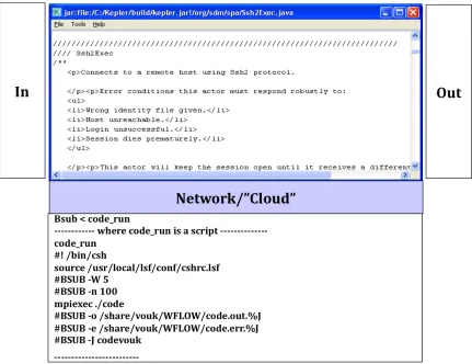
For example, Copying a file, creating an SSH session etc. These actors provide a convenient way for the workflow designers to create workflows without the need to implement the intrinsic details a new. ProcessFileRT [Podh07], developed as a part of the Center for Plasma Fusion Simulation Data (CPES), is a very extensively used generic actor. Another example is SPA’s generic data transfer actor [Chin10]. While individual generic actors are a good way of capturing groups of similar operations that can then be invoked from a single actor (akin to a library of functions) by applying different parameters. On the other hand, scientific processes also have sets of tasks (which are not functionally equivalent or similar, that repeat themselves in different applications across various domains. The templates that can reproduce such patterns in Kepler workflows address the issue by systematically encompassing these tasks into a composite actor entity. Composite actors are themselves small workflows that look to the outside world as a single parameterized actor. Underneath, these workflows have their own director and all inputs are governed through the external input/output ports and parameters.
4.2 Case Study Scientific Workflows
! '-!
operations on the data. For example, transferring the data to a secondary storage for backup. If a failure occurs anywhere along the way, it may mean repeating the whole procedure again. This can waste thousands of CPU hours and a lot of time., Keeping an eye on the simulation and transferring the data as and when they are produced is a tedious manual task that needs the user to be on constant alert. A failure in the simulation makes it even worse. Therefore, casting these manual tasks into automated scientific workflows has been a welcome relief for the scientists from the data management aspect of the experiment, allowing them to focus on the science part of it [Podh07].
Some of the tasks the Center of Plasma Edge Simulation (CPES) automated [Podh07] include monitoring of a simulation for its data output. Transferring the data files to another machine, Converting each data file into HDF5 format., Archiving the HDF5 [HDF510] files to a mass storage system into large chunks, and executing analysis or visualization on the produced data constantly through the various tools to update the user with the current results.
4.2.1 Automation Tasks of the Monitoring Workflows
Based on the analysis done on the Center of Plasma Edge Simulation (CPES), [Podh07] lists the tasks that need to be automated by the workflow. However, many workflows have been developed since, and these tasks are common amongst them as well. Therefore, we list the following tasks as the automation tasks performed by the scientific workflows.
1. Monitoring a simulation for its data output. 2. Transferring the data files to another machine. 3. Converting each data file into HDF5 format.
4. Archiving the HDF5 [HDF510] files to a mass storage system into large chunks. 5. Executing analysis or visualization on the produced data constantly through the
! '$! 4.2.2 Features of a Monitoring Workflow
Based on the speed, time and processing resources utilized, a typical monitoring workflow developed at ORNL [Podh07] needs to have–
1. Security – institution-level security requirements need to be honored, and when accessing resources at ORNL, the workflow authentication and authorization mechanisms need to accommodate one-time password, SSH access, certificates and similar parameters.
2. Configurability – The workflows need to be reasonably re-configurable through parameters (rather than re-write) to allow for changes in resource characteristics, storage paths, etc. It is important that all the resources are compatible with each other or are configurable.
3. Robustness – In case of failure, it is expected that a workflow will attempt and success in recovering from the failure. This may involve, run-time failure masking, or smart re-run feature in combination with provenance recorder, etc.. For instance, on case of failure, the workflow would resume its state by keeping a record of the finished jobs, unfinished jobs and the questionable jobs. It has the ability to repeat only those jobs the execution of which was interrupted thus maintaining the lowest redundancy rate.
4. On-the-fly runs – The amount of data produced as a result of the simulation is often too vast to wait for the complete simulation to finish. Instead, scientific workflows transfer the data files as and when they are produced. This minimizes the risk of losing everything in the case of a failure.
5. Pipes – The monitoring workflows at ORNL use pipelines to keep up with the speed of data generation.
! '%!
for high volumes of complex data. It has been observed, from the execution of the XGC workflows, that 20 percent of simulation time is spent in converting the data into this format. In order to speed up the I/O, the monitoring workflows write the data in a special binary format. This format is quick and efficient. These files are then transferred onto post-processing machines. The conversion of the file into HDF5 format is then carried out in the secondary storage system and on the post-processing machines. This is less expensive and brings about a drastic improvement in the overall performance.
Following are the different monitoring workflows, developed at ORNL, that were used to explore the concept of automatic workflow generation.
4.2.3 XGC Simulation Code
The Center for Plasma Edge Simulation Project (CPES) is a part of the Fusion Simulation Projects funded by the DOE. CPES has created an integrated predictive plasma edge simulation code package called XGC to understand localized mode instabilities which reduce the confinement properties of the plasma and shorten the wall’s lifetime [Podh07, Klas06]. XGC [Ku06] consists of a set of two different particle simulation codes (0 and XGC-1). XGC-1 is a full-f gyrokinetic ion-electron particle code derived from XGC-0, designed for integrated simulation of neoclassical and electrostatic turbulence physics using enormous parallel processors.
! '&! 4.2.4 GEM Simulation Code
Gyrokinetic Electromagnetic Turbulence Simulation (GEM) is another simulation code conducted and it focuses, as the name implies, on gyrokinetic particle simulation of turbulent transport in burning plasmas [Lee07]. It is a delta-f particle code consisting of the dynamics of the gyrokinetic ions and drift-kinetic electrons. The code accurately measures the magnetic fluctuations by studying the well-magnetized plasma physics. The accuracy and precision of the fluctuation levels comes at the cost of large amount of data being produced and stored. ORNL developed a GEM monitoring workflow for the data management of this simulation. Appendix B contains a snapshot of the GEM workflow.
4.2.5 Pixie3D Simulation Code
Parallel, Implicit, eXtended MHD 3D Code (Pixie3D) [Chac04] is a parallel and fully implicit 3D extended MHD solver. The goal of the Pixie3D project is to demonstrate the path for fully implicit MHD in general geometries using state of art scalable solver technology and exploiting massively parallel computing environments. Appendix C contains a snapshot of the Pixie3D workflow.
4.2.6 Analysis of the Monitoring Workflows
All simulation codes of interest here deal with a lot of data. The accuracy and precision achieved by these packages come at a cost of recording and maintaining large amounts of output data, which need to be moved to a more permanent storage as soon as they are produced. Monitoring workflows automate the process of data movement management through a user-friendly interface. making this procedure of complex steps simple.
! ''!
establishing the SSH connection with the remote machine, creating output directories, waiting for the simulation to finish its execution and produce the data files, thereafter splitting the file, transferring the file, appending the file, plotting graphs, text and image archival and making movies. The automation tasks contribute to many repeated operations performed on individual data files where the simulation produces data in time steps [Podh07]. It turns out that most of the monitoring workflows used to monitor an ongoing simulation, and do the post processing data management, follow similar steps. The goal is to determine the pattern followed by the monitoring workflows, use that to develop executable templates to help automate the process of constructing such workflows through parameterization.
Monitoring workflows have an extra visualization step where it is left to the user’s discretion whether to have the data produced plotted or not. The XGC workflow as showed in Appendix A uses AVS Express for visualization. On the other hand Gem data are typically plotted using VisIT and that step is not part of the workflow.
! '(!
Chapter 5 - Workflow Templates and Patterns
!
In software engineering, a design pattern [Gamm95] is defined as “a reusable abstract solution for, or an approach to the solution of, different variations of frequently occurring problems.” A design pattern is structure oriented and distinctly defines the entities and the relationships among them. A template [Barr94] is “a reusable solution that focuses on the explicit details of the solution through parameterization”. It is a canonical but explicit solution to a specific problem, based on a pattern, that can be refined, customized and modified to suit different nuances of the same problem.
A workflow design pattern is a model that is reusable for creating workflows using relevant design pattern primitives. Business process workflows often follow the control flow model, while scientific workflows often follow the data flow model. Furthermore, business workflows tend to be pattern and template driven, while scientific workflows are often one-of creations. However, a pattern (and template) for a scientific workflow would mean combining the notion of both models in order to identify a generic pattern with a high re-usability factor.
! ')!
Monitoring workflows define one such context. In that context the workflow performs a specific set of steps involving post processing of the data that is produced by, for example, a running simulation. Data patterns [Russ05] are the constructs that capture the various ways in which data is represented and utilized in workflows. They are most effective when used for the development of scientific workflows. There are different characteristics that the scientific workflow repeatedly exhibits [Russ05]. This includes:
1. Data visibility, which relates the definition of the workflow construct to the scope of the workflow making them accessible to one and all the workflow components that might need them.
2. Data Interaction that relates to the mode of data communication among the different components of the workflow.
3. Data Transfer specifies the different ways that the data gets passed or transferred from and to the different components within and outside the workflow. Data based routing characterizes the way in which the data can influence the aspects of the workflow, i.e. the control aspect of the workflow taken care of by the data.
In this section we describe some of the basic design patterns that we have identified and used for the monitoring workflows. We describe our approach to identifying the patterns in these workflows, and translating them into re-usable templates, as well as a pre-existing “atomic” template called ProcessFileRT, and the templates built for our research.
5.1 Basic Workflow Patterns
! '*!
Figure 10. In [Bhar08], the authors characterize the scientific workflows by defining the basic workflow structures, specifically data-flow structures.
! Figure 10 – Some basic Workflow Patterns [Bhar08].
![Figure 1 – Architecture of a Workflow Management System [WMC95]](https://thumb-us.123doks.com/thumbv2/123dok_us/1238272.1156371/18.612.123.466.87.419/figure-architecture-workflow-management-wmc.webp)
![Figure 2 – System Architecture of SWfMS [Lin09]](https://thumb-us.123doks.com/thumbv2/123dok_us/1238272.1156371/21.612.96.524.134.405/figure-system-architecture-of-swfms-lin.webp)
![Figure 3 – Lifecycle of a Scientific Workflow [Tan09]](https://thumb-us.123doks.com/thumbv2/123dok_us/1238272.1156371/24.612.133.494.69.344/figure-lifecycle-scientific-workflow-tan.webp)
![Figure 4 - SDM layered architecture [SDMC09]](https://thumb-us.123doks.com/thumbv2/123dok_us/1238272.1156371/35.612.163.489.68.339/figure-sdm-layered-architecture-sdmc.webp)
![Figure 5 - The FIESTA framework [Tcho10]](https://thumb-us.123doks.com/thumbv2/123dok_us/1238272.1156371/37.612.129.503.150.356/figure-the-fiesta-framework-tcho.webp)
![Figure 6 - Architecture of the workflow-managed computations [SDMC09]](https://thumb-us.123doks.com/thumbv2/123dok_us/1238272.1156371/38.612.157.502.89.276/figure-architecture-workflow-managed-computations-sdmc.webp)
![Figure 7 – Architecture of Kepler System [Alti06]](https://thumb-us.123doks.com/thumbv2/123dok_us/1238272.1156371/40.612.106.533.390.577/figure-architecture-kepler-alti.webp)

![Figure 10 – Some basic Workflow Patterns [Bhar08].](https://thumb-us.123doks.com/thumbv2/123dok_us/1238272.1156371/57.612.96.508.134.388/figure-basic-workflow-patterns-bhar.webp)
