An In-Tube Radar for Detecting Defects in Thin-Walled Metal Tubes
B. Nassersharif 1), T. W. H. Caffey 2), R. P. Jedlicka 3), G. V. Garcia 1), E. C. Hensel 1), S. T. Barley 1), E. A. Rede 3) 1) Mechanical Engineering Department, New Mexico State University, Las Cruces, NM
2) Sandia National Laboratories, Albuquerque, NM
3) Electrical and Computer Engineering Department, New Mexico State University, Las Cruces, NM ABSTRACT
A major cause of failures in heat exchangers and steam generators in nuclear power plants is degradation of the tubes within them. The tube failure is often caused by the development of cracks that begin on the outer surface of the tube and prop-agate both inwards and laterally. A new technique will be described for detection of defects using a continuous-wave radar method within metal tubing. The technique is 100% volumetric, and may find smaller defects, find them more rapidly, and find them less expensively than present methods. The In-Tube Radar is in the first year of a three-year joint project between Sandia National Laboratories (SNL) and New Mexico State University (NMSU). The project is funded under the Department of Energy (DOE) Nuclear Energy Research Initiative. The radar consists of two orthogonal magnetic dipoles that are centered on the tube axis and perpendicular to it. One of the electric field components from each dipole is parallel to but vanishes on the tube axis. Hence, an electric dipole located upon, and parallel to, the axis is not coupled to the electric fields of the magnetic dipoles, and should be able to detect the backscatter from a defect anywhere in the tube wall. This favorable situation is degraded when the antenna geometry is non-symmetric with respect to the tube axis, and cross coupling from transmitter-to-receiver, or 'self-clutter', will occur. The degree of asymmetry that can be tolerated with respect to a useful signal-to-clutter ratio is being investigated with results from two different 3D forward-modeling codes. The geometric asymmetry is set by the ability to keep the probe centered in the tube and parallel to the axis as the probe is moved along the tube during use. The design and performance of this important feature will be described. The probe will be battery-powered and linked by fiber optics to the outside of the tube to avoid unwanted reflections, and some of the components will be shown together with pack-aging and assembly details. The schedule for further development and testing for both the scaled-up prototype and the final radar that will lead to planned public demonstrations in 2002 will be described in terms of the major program milestones. INTRODUCTION
The project described in this paper is a joint development effort between Sandia National Laboratories (SNL) and New Mexico State University (NMSU) funded by the US Department of Energy. The goal of the project is to research, design, and develop a new concept utilizing a continuous wave radar to detect defects inside metallic tubes and in particular nuclear plant steam generator tubing. The project is divided into four parallel tracks: computational modeling, experimental prototyp-ing, thermo-mechanical design, and signal detection and analysis. Because this is an on-going project, this paper will focus on processes and some preliminary results.
Introduction to Physical Concepts
The basic concept of the radar is to illuminate the inside of the tube with an electric field that is parallel to the tube wall but which is zero in the vicinity of the tube axis. A small portion of the field penetrates the tube wall, is back-scattered by a defect, and re-enters the tube interior [3]. The larger fraction of the field is reflected back into the interior but, by symmetry, the reflections combine to a very small value near the axis of the tube so that the signal from the defect can be detected.
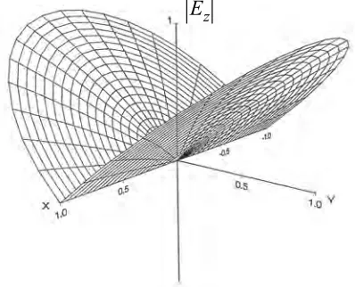
The desired electric field is generated by a small loop that is centered at the origin of a Cartesian coordinate system so that the windings of the loop are in the y-z plane. The magnitude of the vertical electric field, or , has the relative distribu-tion in air as shown in Fig. 1.
The -field is zero everywhere in the xz-plane, so that an electric dipole can be placed along the z-axis without being coupled to the transmitting loop. The geometry of the loop transmitter and an electric dipole receiver within a tube is shown in Fig. 2. The size of the defect shown in the tube wall is greatly exaggerated for illustration. The z-axis coincides with the axis of the tube, and the electric dipole is placed above the loop by a spacing which must be chosen because the distribution of varies with the separation distance along the z-axis.
As a specific example, consider an Inconel tube with an inside diameter of 2.2cm and a wall thickness of 0.127cm
E
zE
zE
z(0.05 inches), and examine the -distribution throughout an xy-plane that is 2.2 cm above the loop source. This might be the location of the lower portion of the receiving dipole. The most favorable case occurs when the tube wall is replaced with air, and this distribution is shown in Fig. 3. The appearance is that of a folded, circular disc whose rim corresponds to the tube wall. A clean null in the xz-plane is present as before. When the metal wall is introduced, the situation changes as shown in Fig. 4. The fold of the disc is rotated 90 degrees from the air-tube case, and is non-zero along the y-axis except at y = 0. The maximum value, at the x-axis rim, is 26% of the maximum at the y-axis rim in Fig. 3, and the cross-coupled field near the z-axis is very small.
NUMERICAL MODELING
The modeling of the problem is carried out through two parallel efforts; one at Sandia and the second at NMSU.
San-Figure 1 Distribution of the vertical electric field in air Figure 2 Geometry of the tube and antennas
Figure 3 Distribution of the vertical electric field within an air tube
Figure 4 Distribution of the vertical electric field within a metal tube
E
zCTUBE to model the problem under non-symmetric conditions are currently on-going [5].
The numerical modeling effort at NMSU has focused on further development of the NMSU finite-element code to model cracks in heat exchanger pipes. A computer program has also been developed for generation of the structured mesh to be used for the cylindrical geometry.
Work on CTUBE
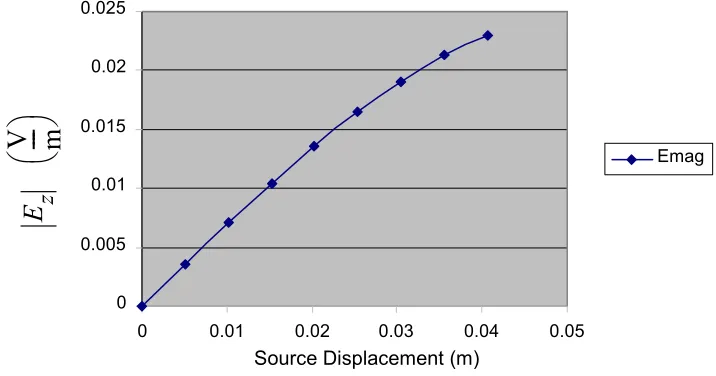
A series of numerical experiments were performed to test the capability of CTUBE (as provided by SNL) to estimate the “self-clutter” within the heat exchanger pipe. CTUBE provides an estimate of this by computing the fields in a hole situ-ated within an infinite conducting medium. Due to the symmetry of the problem, the expected result was obtained when the x-directed source was moved along the x-axis. This is depicted in Fig. 5 the plot of the magnitude of the on-axis electric field as
a function of source displacement (along the x axis).
It is observed that the on-axis field increases when the magnetic dipole source is offset. The question is “how signifi-cant is this increase relative to the change in on-axis field induced by the presence of a defect in the heat exchanger tube?” Unfortunately, CTUBE will not accommodate simulation of the defects and thus, the finite-element method (FEM-Tube) com-puter code is being developed at NMSU to model the problem in its entirety. Another anticipated use of the comcom-puter code CTUBE was to predict the “self-clutter” when the source was offset from the centerline in an arbitrary direction. However, due to the limitations of the modified Bessel function routines used to compute the series solution, no useful results were generated for this case and this portion of effort is under development at Sandia.
NMSU FEM Code
The FEM code[4] being modified for this effort solves Maxwell’s equations inside, within and outside the heat exchanger tube for realistic problem geometries. It is based upon the following formulation. We begin with Maxwell’s equa-tions in time-harmonic form:
, and (1)
. (2)
This representation allows for magnetic as well as electric losses given the following tensor forms.
Figure 5 Axial Electric Field vs. source displacement 0
0.005 0.01 0.015 0.02 0.025
0 0.01 0.02 0.03 0.04 0.05
Emag
Source Displacement (m)
E
z
V
----
m
∇
×
E
j
ωµ
0µ
r˜
H
–
–
M
i=
∇
×
H
j
ωε
0ε
r˜
E
–
+
J
i, and (3)
. (4)
The symbols in equations (1) through (4) are defined as: electric field in ,
magnetic field in ,
electric current density in ,
magnetic current density in ,
permittivity of free space in ,
permeability of free space in , relative permeability tensor,
relative permittivity tensor, the radian frequency, magnetic conductivity in ,
electrical conductivity in , and
.
For this problem, the impressed electric current density, , will be zero. We also take and accounts for
µ
r˜
µ
rxj
σ
x∗
ωµ
0---–
0
0
0
µ
ryj
σ
y∗
ωµ
0---–
0
0
0
µ
rzj
σ
z∗
ωµ
0---–
=
ε
r˜
ε
rxj
σ
xωε
0---–
0
0
0
ε
ryj
σ
yωε
0---–
0
0
0
ε
rzj
σ
zωε
0---–
=
E
Volts
m
---H
Amps
m
---J
Amps
m
2---M
Volts
m
2---ε
0Farads
---
m
µ
0Henries
---
m
µ
r˜
ε
r˜
w
=
2
π
f
σ∗
Ω
m
----σ
Siemens
---
m
j
–
1
the losses in the Inconel tube wall. For the magnetic antenna, and the electric field form will be used. Solving for in the first curl equation and substituting we have the vector wave equation:
. (5)
Applying the Galerkin method of weighted residuals by forming an appropriate inner product, yields
. (6)
By a vector identity and Gauss’ divergence theorem the first term is split into volume and surface integral terms.
. (7)
The domain is discretized and a continuous approximation to the electric field, due to excitation by the magnetic source, is determined throughout the domain simply by specifying the material properties throughout the region. The size of the computational domain is restricted by using a perfectly matched layer (PML).
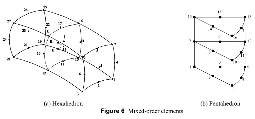
The FEM-Tube code has two mixed-order element types; a 27-node hexahedron and an 18-node pentahedron. The element types are shown in Fig. 6 (a) and (b).
FEM Mesh Generation
To perform the FEM modeling requires a mesh of suitable nodes and elements to discretize the problem for numerical solution. A computer code was developed to generate structured meshes of the cylindrical heat exchanger tube geometry. The incorporation of defects is accommodated by a change in the material parameters of one or more of the elements within the mesh. The mesh generator program uses pentahedrons to create a cylindrical center section, then four additional regions are added using hexahedrons: air inside the tube, the pipe wall, air outside the tube and the PML region that truncates the compu-tational domain.
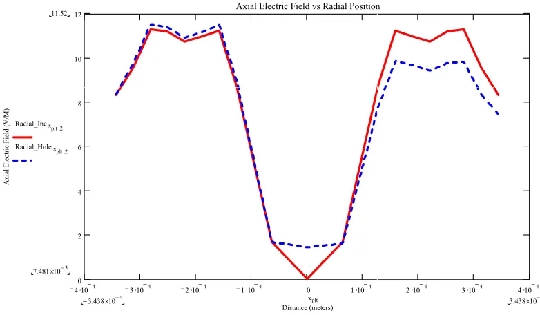
The configuration for a loop transmitter and receive monopole was analyzed using the finite element method both with and without a defect. The received electric field as a function of position inside the tube is plotted in Fig. 8. The solid curve is proportional to the received voltage for a perfect tube; the dashed curve is the response when a defect is present. The increase in on axis field represents the presence of a defect. By transmitting with one, then the other loop antenna, the azi-muthal position of the defect can be determined.
(a) Hexahedron (b) Pentahedron
Figure 6 Mixed-order elements
M
i≠
0
H
∇ µ
r˜
1 –
∇
×
E
ω
2µ
0ε
0ε
r˜
E
–
×
∇ µ
r˜
1 –
×
M
i=
T
∇ µ
r˜
1 –
∇
×
E
ω
2µ
0ε
0ε
r˜
E
–
×
⋅
d
V
V
∫
T
∇ µ
r˜
1 –
×
M
i
⋅
d
V
V
∫
–
=
∇
×
T
(
) µ
r˜
1 –
∇
×
E
⋅
d
V
V
∫
T
µ
r˜
1 –
∇
×
E
×
⋅
d
S
S
∫
ω
2µ
0ε
0T
ε
r˜
E
(
)
⋅
d
V
V
∫
–
–
T
∇ µ
r˜
1 –
×
M
i
⋅
d
V
EXPERIMENTAL DESIGN
The basic operation of the ITR sensor is based upon transmission and reception of an electronic signal within the heat exchanger tube. This requires a transmitter to generate the fields and a receiver along the centerline of the tube. A reference signal is generated in the signal processing instrumentation and coupled to the sensor itself via fiber optic cable. It is amplified and alternately applied to two orthogonal loop antennas via a switching network. The transmitter produces electromagnetic fields within the tube and its wall. The frequency of operation is selected such that the two-way path through the metal wall of the heat exchanger tube is one skin depth, a total power loss of 8.8 dB. The loop antennas are symmetrically placed within the sensor so that when either one transmits in the absence of a wall defect the electric field at the receive monopole antenna can-cels producing zero volts. The presence of a crack anywhere in the wall (interior or exterior) precludes the conditions for exact cancellation of the field; an increase in voltage at the terminals of the receive monopole indicates a defect. Fig. 9 shows the
Figure 7 Side View of Computational Domain
Figure 8 Radial variation of axial electric field across tube
PML
PML
Air
Air
Air
Air
4.104 3.104 2.104 1.104 0 1.104 2.104 3.104 4.104 0
2 4 6 8 10
12 Axial Electric Field vs Radial Position
Distance (meters)
Ax
ial E
lectric Field
(V/M
)
11.52
7.481 10× −3
Radial_Incxplt 2, Radial_Holexplt 2
,
3.438 10× −4
3.438
ment. The testing of the experimental circuit is planned for summer 2001. THERMO-MECHANICAL DESIGN
Several concepts were considered in the thermo-mechanical design of the sensor package [6], including the ability to maintain the receiving antenna on the centerline of the tube, ability to easily adjust the separation distance between the trans-mitting and receiving antennas, electromagnetic compatibility of all materials, ease of manufacturing, and method for translat-ing the device through a straight and curved tube. A complete solid model of the design was completed, and used as the input information for a finite element stress analysis of the device under various acceleration and loading conditions. An exploded assembly view of the mock-up probe is illustrated in Fig. 9.
The device consists of a forward section, housing three circuit boards (data communications, transmitter amplifier, and power supply) and two wire-round ferrite rods positioned orthogonal to one another and the axis of the tube. The after sec-tion of the housing contain two boards, for receiver antenna processing and optical communicasec-tions, and power supply, along with a monopole receiver antenna aligned with the tube axis. The two ends of the housing are assembled, and are threaded externally with 12 pitch threads. One end of the housing has a right hand thread, while the opposing end is threaded with a left hand thread. This allows the outer, center section of the body to be rotated and adjust the separation distance from the transmit-ter to the receiver.
A series of bristles, much like hair brush bristles, are installed on the exterior surface of the device to provide a means for centering the device on-axis, while still enabling the sensor to pass through restrictions such as tube sleeves, and into the curved portion of the tube. The end cap is design to be easily removable, and the geometry can be readily adapted to mate the sensor itself with a variety of commercially available feeder mechanisms. For our initial testing, we are using an industry stan-dard ZTEC probe feeder.
DATA ACQUISITION SYSTEM AND FIBER OPTIC COMMUNICATION
At the start of the project, it was decided that a fiber optic system would be used for all communication between the data acquisition system and probe due to electromagnetic interference constraints. This would require three separate optical signal paths: one optical signal will be used to drive the probe antenna, the second optical signal will be used as a switch con-trol, and the third optical signal will be the signal detected by the probe receiver antenna.
Initially, a commercial off-the-shelf voice-link fiber optic kit was evaluated. On the bases of this evaluation, a new circuit was designed, constructed, and tested. This new circuit is used to control the output signal generated by the probe antenna and for the switch. A second circuit with a high-end optical transmitter and receiver was also designed. This circuit is used for the signal detected by the probe receiver antenna.
National Instruments LABVIEW software program is used for the computer/user interface and for control of the data
acquisition system. Several LABVIEW programs were written to control the optical fiber system, generate the drive signal for the probe antenna, and for acquisition of the receiver antenna signal. A National Instruments 250 kS/s data acquisition board was used during this phase of the project. From these initial studies, it was determined that a 1.5 MS/s data acquisition board would be needed to acquire the receiver antenna signal. In addition to this, a 1 MS/s output board would be needed to generate the drive signal for the output antenna and to control the drive mechanism used to push and pull the probe along the tube. Signal Analysis and Processing
The Data Acquisition System and Fiber Optic Communication team is also responsible for the interrogation of the signal detected by the probe receiver antenna. Pattern recognition will be used to detect tube damage and determine the type of damage. The idea here is to stream the receiver signal to the computer hard drive using LABVIEW and to simultaneously use a MATLAB software program within LABVIEW for damage detection and type. A MATLAB program was written to detect square pulses inserted in a random signal. Once actual data is available for the receiver antenna, additional MATLAB pro-grams will be written and tested. In the meantime, we are continuing with our study of pattern recognition and how it can be used to detect and classify damage.
PROJECT PLANS AND FUTURE WORK
The In-Tube Radar project is a three-year program and is currently into its second year. The experimental results will be available by the end of the second year of the project and the third year of the project will primarily focus on miniaturiza-tion of the device for actual size tubes. The computaminiaturiza-tional model is being developed and validated in parallel with the experi-mental work. Additional computational results will be available at the time of the presentation of this work at the SMiRT-16 conference.
ACKNOWLEDGEMENTS
This work is sponsored by the Department of Energy’s Nuclear Energy Research Initiative (Grant Number DE-FG-3-99SF21986).
REFERENCES
1. Caffey, T. 1997. “Elements of a Continuous-Wave Borehole Radar,” Technical Report SAND97-1995, Sandia National Laboratories, Albuquerque, NM, August.
2. Caffey, T. 1997. “A Tool to Detect External Cracks from within a Metal Tube,” Technical Report SAND97-0170, Sandia National Laboratories, Albuquerque, NM, August.
3. Wait, J. R. and Hill, D. A., 1977, “Electromagnetic Fields of a Dipole Source in a Circular Tunnel Containing a Surface Wave Line”, International Journal of Electronics, 1977, Vol. 42, No. 4, pp 377-391.
4. Jedlicka, R.P., Castillo, S.P., and Warne, L.K., “Coupling Through Tortuous Path Narrow Slot Apertures into Complex Cavities,” IEEE Transactions on Antennas and Propagation, Volume 48, No. 3, March 2000, pp. 456 - 466.
5. Lazarev, Y. N. et al 2000. “Three-Dimensional Unified Codes for Solving the Forward Problem of Singlewell Electro-magnetic Logging”, Report on Task 4A of Contract AS-5553, Sandia National Laboratories, Albuquerque, NM, March. 6. Brooks, S. 2000, “Continuous Wave In-Tube Radar: Development of an Experimental Prototype,” M.S.M.E. thesis, New