Green Energy Based Electrical Power
Generation System
Ronak .L Tandel1, Dipen .D Patel2, Akash .M Tandel3, Keyur .M Mistry4, Shani .M Vaidya5
UG Student, Dept. of Electrical Engineering, Valia Institute of Technology, Bharuch, Gujarat, India1-4
Assistant Professor, Dept. of Electrical Engineering, Valia Institute of Technology, Bharuch, Gujarat, India5
ABSTRACT: Due to the rapid growth in the usage electricity and the price combustion fuel, motivate us to use natural air as a fuel to generate electricity, this paper shows a natural air and industrial waste gases power driven electricity generating system, Which can produced electricity at very low cost using air or waste gas as a fuel, This system will be extremely handy at the place where we have to control only ON and OFF switches for operating and charging purpose of the system, The main aim of this work is to minimize the running cost, charging time, pollution, recover losses of electrical generator and also to maximize it efficiency so that it can run for maximum time as possible to the each and every user, so in this paper we have described a nature air driven electricity generating system.
KEYWORDS:Waste gas, Compressed air, Air motor, Alternator, Dynamo, AutoCAD.
I. INTRODUCTION
Electric power is basic necessity of any industries and it can be very costly to produce electricity from conventional method for the industrial purpose, this reason inspired to use the industrial waste gases to generate electric power, normally chemical industrial have large number of waste gases like carbon dioxide CO2 is a colourless and odourless gas which have density 1.977 kg/m3 (gas at 1 atm and 0°C),specific heat capacity 37.135 J/K mol and vapour pressure 5.73 MPa (20°C), carbon monoxide CO is a colourless, odourless, and tasteless gas that is slightly less dense than air have density of 1.250 kg/m3 at 0°C, 1 atm 1.145 kg/m3 at 25°C, (1 atm), specific heat capacity 29.1 J/K mol, vapour pressure0.1 MPa, phosgene COCl2is colourless and suffocating gas which have density of 4.248 g/L (15°C, gas), Heat capacity at constant pressure (Cp) (1.013 bar and 25 °C (77 °F)) : 5.769014E-02 kJ/(mol.K) and vapour pressure of 1.6 atm (20°C) etc, they store this gases in the storage tanks of huge capacity and emit them at the appropriate time, this thing goes completely in the loss account of industrial, therefore here shown the design (AutoCAD) and implementation of a electric generator which can run on industrial waste gases as well as on natural air, the system is based on compressed gas power with the generating system, this compressed gas technology provide user a very cost-efficient electricity to the industrial which stored the waste gases in a compressed tank. so this system can be very beneficial and cost efficient for those industries.
II. SYSTEM DESCRIPTION
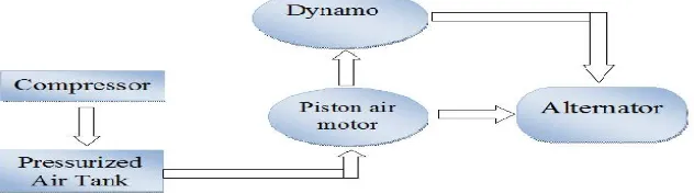
This system consist of waste gases, compressor, storage tank, air motor, alternator and dynamo, block diagram of this system is shown below fig 1.
The first thing in this system is to start compressor which will forced waste gases to store in the compressing tank at very high pressure, this process is already present in the industries so no need for additional equipment
Fig. 2 front view in AutoCAD design
The fig 2 is front view of this system as shown there all component are installed on a metal stand to provide mechanical support to the system, compressor and pressurize tank are installed near the system and connection pipe is provided from pressurize tank to the inlet of air motor, than after this high pressure compressed gas will be carried out to drive an air motor it will produced rotational motionand start driving alternator
The fig 3 is top view of this system, here one more connecting pipe is shown from outlet of air motor to the end of metal stand which will drive dynamo so there is no waste of compressed gas, this dynamo will give DC excitation to the alternator.
III. DETAIL DISCRIPTION OF ALL COMPONENTS
A. Compressor
Fig. 4 compressor unit
Here compressor is used to compressed waste gases in the pressurized tank, most of the compressor you’ll run across do this job with a reciprocating piston. It is just like a small internal combustion engine, a convention piston compressor has crankshaft, a cylinder and a value head the crankshaft is driven by either an electric motor or a gas engine, normally industries preferred an electric motor of near about 5 to 10 hp which rotate at 2000 to 3000 rpm asper the requirement, this need same amount of electricity to fill the pressurized tank, the industries store there waste gases near about 800 to 1200 psi in the high capacity storage tanks, an compressor unit is shown in fig 4
B. Pressurized Tank
The tank used to stored compressed gas is just like a battery, as we know rechargeable batteries probably can be considered the best power-storing devices for various forms of renewable energy, but compressed gas energy storage is also promising and should not be overlooked, so here in system we are going to use this technology to storing waste gas or natural air, the stored tanks used in industries are design to store waste gases at very high pressure, huge amount of waste gases are stored by the industries which can be used to produce electricity.
C. Air motor
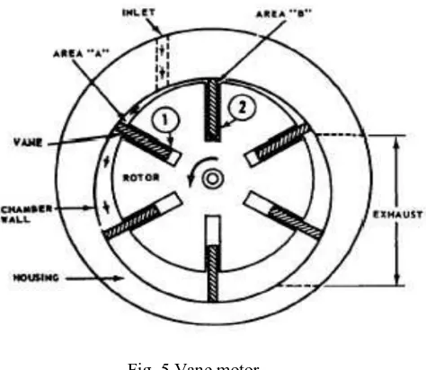
Fig. 5 Vane motor
Vane type air motor is shown in fig 5, this particular motor provides rotation in only one direction, and the rotating element is a slotted which on a drive shaft.Vane motors are often used for tools requiring lower power, such as portable tools.
Fig. 6 Piston motor
Piston-type motor is shown in fig 6, this are the most commonly used in hydraulic system. They are basically the same as hydraulic pumps expect they are used to convert hydraulic energy into mechanical (rotatory) energy. High-power machines that require a high starting torque use piston motor. Low-pressure, high-velocity tool like dental drills and jet engine starter, so in our system we are going to use a motor which can be suitable, and can also increase the efficiency of the system.
D. Alternator
Fig. 7 Alternator
An alternator is shown in fig 7, this is an electrical generator that converts mechanical energy into electrical energy in form of alternating current. and as we know than now a day’s AC current is used commercial as well as in the industrial application, this machine consist of a rotating magnetic core (rotor) and stationary wire (stator), a conductor moving relative to magnetic field develop an electromotive force (EMF) in it as per the faraday’s law, so over here we are trying to develop and alternator which work on low speed (RPM) and the torque required by it will also be low so that it can run for maximum time possible, over first aim is to minimized the losses of alternator as well as for the whole system to the possible level for the user of this system, so that it can be beneficial to industrial and commercial once
E. Dynamo
The smallest form of the DC generator is known as dynamo which work, on the faradays law as same of alternator, here Dynamo produces a steady supply of direct current electricity when it spins around. Like a DC motor, a DC generator uses a commutator. It sounds technical, but it's just a metal ring with splits in it that periodically reverses the electrical contacts from the generator coil, reversing the current at the same time. As we saw up above, a simple loop of wire automatically reverses the current it produces every half-turn, simply because it's rotating, and the commutator's job is to cancel out the effect of the coil's rotation, ensuring that a direct current is produced.
This DC current will be used to provide DC excitation to the Alternator so that the maximum amount of voltage can be produced and the other reason behind separating the DC generator from the Alternator is to reduce the torque of Alternator to increased efficiency of the system This DC generator will run on the exhaust air coming from the air motor , this exhaust air contain same amount of pressure which can be enough to run an small DC generator which is placed at the last position as shown in Fig. 8
VI
.
AUTOCAD SIMULATION AND DISCUSSION Table of waste gases
GASES STORED ON PSI DENSITY
Carbon dioxide CO2 800-1200 1.977 kg/m3
Carbon monoxide CO 800-1200 1.250 kg/m3
Nitrogen N2 800-1200 1.25 kg/m3
Phosgene COCL2 800-1200 4.25 kg/m3
Table. 1 list of waste gases
The Table 1 shows the some of waste gases produce by the industrial, which they need to store at nearly 800-1200 psi in the pressurize tank, and also the density of the gases is shown in the table.
Table of air motor reading
R.P.M 1200
H.P 1.5
kW 1.11
Torque 7
Pressure required 6.3 bar
Table. 2 air motor reading
The air motor we are going to use in this system must fulfil the criteria shown in table 2, the air motor will be vane type so that exhaust of the motor can also be used to drive dynamo.
Table of Alternator reading
Voltage 120
Current 50
R.P.M 1100
H.P 1.25
Toque 6
kW 0.93
Table 3 shows the specification of the alternator which is going to be use in this system, and also shown the amount of electricity produce by the alternator.
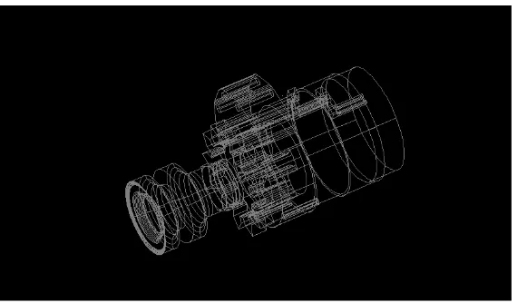
AutoCAD simulation of Alternator
Fig. 9 AutoCAD simulation of Alternator
Fig. 9 shows the simulation of the alternator done by using AutoCAD 2009, the simulation is done in 3D mode so that it can be batter to understand
AutoCAD simulation of Dynamo
Fig. 10 AutoCAD simulation of Dynamo
Fig. 10 shows the AutoCAD simulation of dynamo done in AutoCAD 360, also the fan (wings) is shown in the simulation, and this fan (wings) will be driven by the exhaust of the air motor as sad above.
V. CONCLUSION
user can be able to produces electric energy at very low cost and co-friendly manner because it is totally based on natural air which is present at all over the places. This can be the most innovative and user friendly power generation system.
REFERENCES
[1] British Electricity International (1991). Modern Power Station Practice: incorporating modern power system practice (3rd Edition (12 volume set) ed.).
[2] Babcock & Wilcox Co. (2005). Steam: It’s Generation and Use (41st ed.).
[3] Thomas C. Elliott, Kao Chen, Robert Swanekamp (coauthors) (1997). Standard Handbook of Powerplant Engineering (2nd ed.). McGraw-Hill Professional
[4] http://www.bbc.co.uk/news/uk-england-tyne-21586177 [5] http://www.nationaltrust.org.uk/cragside/
[6] Jack Harris (14 January 1982), "The electricity of Holborn", New Scientist [7] Nuclear Power Plants Information, by International Atomic Energy Agency
[8] Wiser, Wendell H. (2000). Energy resources: occurrence, production, conversion, use. Birkhäuser. p. 190. ISBN 978-0-387-98744-6. [9] SWEB's Pocket Power Stations
[10] J.C. Hensley (Editor) (2006). Cooling Tower Fundamentals (2nd ed.). SPX Cooling Technologies.
[11] Beychok, Milton R. (1967). Aqueous Wastes from Petroleum and Petrochemical Plants (4th ed.). John Wiley and Sons. LCCN 67019834. (Includes cooling tower material balance for evaporation emissions and blow down effluents. Available in many university libraries)
[12] River keeper, Inc. v. U.S. EPA, 358 F.3d 174, 181 (2d Cir. 2004) (“A single power plant might impinge a million adult fish in just a three-week period, or entrain some 3 to 4 billion smaller fish and shellfish in a year, destabilizing wildlife populations in the surrounding ecosystem.”). [13] U.S. Environmental Protection Agency, Washington, DC (May 2014). "Final Regulations to Establish Requirements for Cooling Water Intake Structures at Existing Facilities." Fact sheet. Document no. EPA-821-F-14-001.
[14] McGeehan, Patrick (2015-05-12). "Fire Prompts Renewed Calls to Close the Indian Point Nuclear Plant". New York Times.
[15] American Association for the Advancement of Science. AAAS Annual Meeting 17 - 21 Feb 2011, Washington DC. "Sustainable or Not? Impacts and Uncertainties of Low-Carbon Energy Technologies on Water." DrEvangelosTzimas, European Commission, JRC Institute for Energy, Petten, Netherlands.
[16] Carbon Trust, Future Marine Energy. Results of the Marine Energy Challenge: Cost competitiveness and growth of wave and tidal stream energy, January 2006
[17] http://blogs.worldbank.org/climatechange/will-china-and-us-be-partners-or-rivals-new-energy-economy [18] CCGT Plants in South England, by Power Plants Around the World
[19] Dick Strawbridge And JemStansfield- and engineers from England made a TV show on air powered automobile