ISSN (Print) : 2320 – 3765 ISSN (Online): 2278 – 8875
I
nternational
J
ournal of
A
dvanced
R
esearch in
E
lectrical,
E
lectronics and
I
nstrumentation
E
ngineering
(An ISO 3297: 2007 Certified Organization)
Vol. 5, Issue 7, July 2016
Design and Implementation of Messaging
System Using Braille Code for Virtually
Impaired Persons
P. H. Zope1, Harshal Dahake2
Assistant Professor, Dept. of E&TC, SSBT’s C.O.E.T. Bambhori Jalgaon, India1
PG Student [E&TC], Dept. of E&TC, SSBT’s C.O.E.T. Bambhori Jalgaon, India2
ABSTRACT: The system is specially designed for the visually impaired community to connect, communicate and socialize without vision. Enabling those who are blind to accomplish important tasks with just their sound and touch via a comprehensive eye free. Now a day physically impaired people have no access of advanced communication technologies. To aware the blind peoples with the advance telecommunication system, our approach focused on design a Short Message Service (SMS) system for them, it interface Braille pad with the cell phone. For sending a SMS, the microcontroller IC AT89S52 is used which converts the typed Braille letter on Braille pad to the English alphabets using the Lookup table. The first blind person sends the message to the another blind person’s mobile number which is connected via microcontroller which reads the message using GSM module which operates on AT commands and then converts the letters received in the message into the Braille language using the lookup table in its memory. With the help of 6 relays Microcontroller vibrates the Braille pad on which the blind person can read the message. LCD and Loud speaker are used for display and voice announcement it helps verification of the system response.
KEYWORDS: Microcontroller, Braille Pad, SMS, Message.
I.INTRODUCTION
Now a day there are a huge range of mobile phones on the market, ranging from the most basic (all they do is make calls) to models more complex and powerful than a desktop computer. But the visually impaired people cannot able to use this facility[1]. Louis Braille was the father and inventor of Braille system. This is a worldwide universally accepted basic system that is being used by blind people for reading and writing purpose. Braille is read by passing the fingers over characters designed as an arrangement of one to six embossed points. Braille is not a language but it is the way of writing other languages. Louis Braille self-invented raised dot system getting inspired by the wooden dice given by his father; consisting of only six dots which corresponded to letters. The six-dot system helps to recognize alphabets or letters passing fingertip sensing all the dots at once. These systems are arranged in rectangular patterns of dots so that the system can easy to learn [2-5].
ISSN (Print) : 2320 – 3765 ISSN (Online): 2278 – 8875
I
nternational
J
ournal of
A
dvanced
R
esearch in
E
lectrical,
E
lectronics and
I
nstrumentation
E
ngineering
(An ISO 3297: 2007 Certified Organization)
Vol. 5, Issue 7, July 2016
II. FUNCTIONAL BLOCK DIAGRAM AND DESCRIPTION
The functional block diagram of the entire system is divided in to two parts named as transmitter and receiver shown in figure 1. All the major subsystem blocks are shown with their interconnections to each module. It consists of Braille Keypad, AT89S52 microcontroller, GSM MODEM (SIM300), relay, solenoid keypad and power supply.
Transmitter Receiver
Figure 1. Functional Block Diagram of the system
III. SYSTEM ELEMENTS
The implementation of all the features stated above we need to have a constant interaction between the hardware and Software like Braille Keypad, Microcontroller, GSM Module, Relay, Solenoid Keypad, Software.
Figure 2. Braille Keypad
A. Braille Keypad
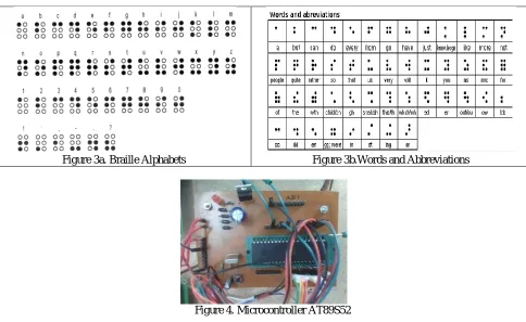
Electronic Braille keypad is shown in figure 2 it is specially designed for the visually impaired or blind peoples. The concept of Braille keypad arises from the wooden dice. It is used to enter the text message in the form of characters, alphabets etc. only for the blind peoples having the specific standard pattern for each character or alphabet. Group of six raised dots or bumpy dots represent the particular letter. Braille keypad is consisting of 3x2 matrixes by which we can display 64 different characters as shown in figure 3a and 3b. All the six dots are arranged in the form of rectangular array design. Each character has standard symbolic pattern respective to its Braille keypad. This electronics Braille keypad has Ok, Send, and Space button. Ok button used to fix that particular character and ready to accept next character. Space button used to give space between the characters. Send button used to transmit typed text message.
In recent days the Electronic Braille note takers portable devices are available in the market places with Braille keyboards the Braille readers can use to enter information. The text stored in these devices can be read with a built-in Braille display or the device can read aloud with a synthesized voice. These devices are handy for taking notes in class, and often have built-in address books, calculators, and calendars, too.
B. Microcontroller
ISSN (Print) : 2320 – 3765 ISSN (Online): 2278 – 8875
I
nternational
J
ournal of
A
dvanced
R
esearch in
E
lectrical,
E
lectronics and
I
nstrumentation
E
ngineering
(An ISO 3297: 2007 Certified Organization)
Vol. 5, Issue 7, July 2016
signal into digital signal. The inbuilt embedded C program monitors and compare digital signal coming from Braille keypad. These digital signals are compared with specified level defined by the programmer to identify the key entered by the user. The execution speed of the microcontroller is 20MHz achieved using external crystal oscillator [14].
Figure 3a. Braille Alphabets Figure 3b.Words and Abbreviations
Figure 4. Microcontroller AT89S52
C. Global System for Mobile Communications (GSM) Module interface
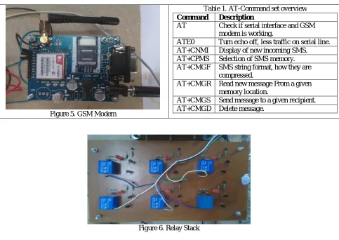
In recent years the most widely adopted cellular GSM module is shown in figure 5. GSM module is used to send and receive short text messages. The subscriber identification module (SIM) is interfaced with the module it permit the use of mobile service. This technology enables the system as a wireless system. This is a plug and play GSM Modem with a simple to implement RS232 and TTL serial interface. It is used to send and receive message, make and receive calls, allow internet services and do other GSM operations. AT commands shown in table 1 are executed on microcontroller to obtain the services. The GSM module receives the signal as AT commands executes and performs various operations. GSM Module is connected to the controller and transmits the incoming messages to the controller. It also receives the messages from controller.GSM uses a variation of time division multiple access (TDMA) and is the most widely used of the three digital wireless telephony technologies (TDMA, GSM, and CDMA). GSM digitizes and compresses data, then sends it down a channel with two other streams of user data, each in its own time slot. It operates at either the 900 MHz or 1800 MHz frequency band, better signal quality, status lights indication.
D. Relay
ISSN (Print) : 2320 – 3765 ISSN (Online): 2278 – 8875
I
nternational
J
ournal of
A
dvanced
R
esearch in
E
lectrical,
E
lectronics and
I
nstrumentation
E
ngineering
(An ISO 3297: 2007 Certified Organization)
Vol. 5, Issue 7, July 2016
The electromechanical action of relay requires current approximately 100mA, the current supplying capability of the microcontroller’s port is less that this requirement. In such situation externally transistor amplifier or darlington pair circuit are used to raise the current carrying and delivering capacity of the port.
Figure 5. GSM Modem
Table 1. AT-Command set overview
Command Description
AT Check if serial interface and GSM modem is working.
ATE0 Turn echo off, less traffic on serial line. AT+CNMI Display of new incoming SMS. AT+CPMS Selection of SMS memory. AT+CMGF SMS string format, how they are
compressed.
AT+CMGR Read new message From a given memory location.
AT+CMGS Send message to a given recipient. AT+CMGD Delete message.
Figure 6. Relay Stack
E. Solenoid Sensing Keypad
Figure 7 shows solenoids are the most common actuator components. The basic principle of operation involves a moving ferrous core (a piston) that will move inside a wire coil as shown in figure 8. Normally the piston is held outside of the coil by a spring. When a voltage is applied to the coil and current flows, the coil builds up a magnetic field that attracts the piston and pulls it into the centre of the coil. The piston can be used to supply a linear force.
Figure 7. Solenoid
Figure 8. Solenoid operation
ISSN (Print) : 2320 – 3765 ISSN (Online): 2278 – 8875
I
nternational
J
ournal of
A
dvanced
R
esearch in
E
lectrical,
E
lectronics and
I
nstrumentation
E
ngineering
(An ISO 3297: 2007 Certified Organization)
Vol. 5, Issue 7, July 2016
Figure 9. Solenoid Sensing Keypad
F. Software
This Proposed System uses Keil software to convert Embedded C programme to machine level. The Keil tool kit includes three main tools, assembler, compiler and linker. An assembler is used to assemble the Embedded C program. A compiler is used to compile the C source code into an object file. A linker is used to create an absolute object module suitable for our in-circuit emulator [14].
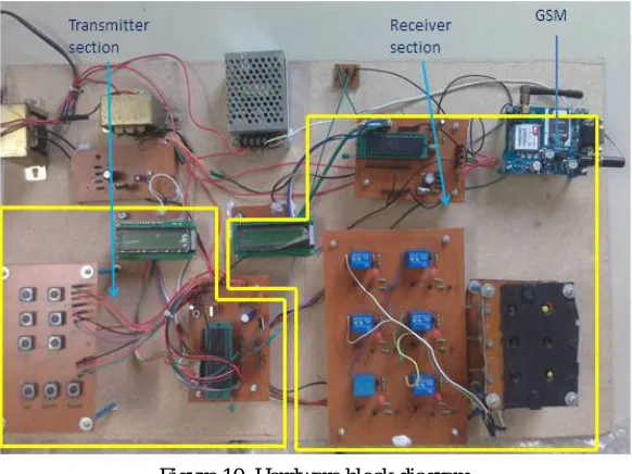
IV. HARDWARE IMPLEMENTATION AND DESCRIPTION
The hardware implementation is shown in figure 10, it has two sections. The first section transmitter consists of Braille keypad interfaced with microcontroller. The purpose of microcontroller is to converts the Braille key signal into equivalent english code by using the lookup table. The lookup table is nothing but equivalent hexadecimal code of Braille alphabet or words; they are stored inside the microcontroller. The 8K Bytes of In-System Programmable (ISP)
Figure 10. Hardware block diagram
ISSN (Print) : 2320 – 3765 ISSN (Online): 2278 – 8875
I
nternational
J
ournal of
A
dvanced
R
esearch in
E
lectrical,
E
lectronics and
I
nstrumentation
E
ngineering
(An ISO 3297: 2007 Certified Organization)
Vol. 5, Issue 7, July 2016
in two strings. The internal registers of the microcontroller hold the message. The SEND button is used for passing the message hold by the register to the GSM modem. But the application software in the microcontroller first encloses the message into AT commands as listed in table 1. The AT commands initialize the GSM modem and activates the message services. Once these services are activated on GSM modem, the message is transmitted to the recipient mobile.
The second section is receiver, it is essential to receive a message. When a sender sends the message to the blind person then his mobile is interfaced with the microcontroller. The microcontroller receives the message through the AT commands and converts the letters of the message in to the equivalent electrical signals of Braille language by using the lookup table which are stored in the internal memory of microcontroller. These electrical signals are fed to activate the 6-relay stack with solenoid valve interfaced with microcontroller. To understand the received message the blind person has to place his hand over the stack of solenoid valve, the valves are arranged in such a way that the person can understand looks like Braille letters. An electrical signal energizes the relay and the respective solenoid valve does vibration and these vibrations are sensed by the blind person.
V. RESULT AND DISCUSSION
The embedded C application will always be in running state at the background once it is started. Once application is downloaded on microcontroller, all message related activities are by default performed by application. With respect to user perspective, application working is divided in two ways – One application is used for sending messages and other when application is used to read received messages.
To send a message “abc” as shown in figure 11, the visual impaired person should have knowledge of Braille language. The Braille keypad is needed to pass the message
Figure 11 Send and receive message “abc”
1) Braille keypad has Ok, Send, and Space button.
Ok button used to fix that particular character and ready to accept next character means typed character get stored inside the database of microcontroller.
Space button used to give space between the characters.
Send button used to transmit typed text message.
2) Microcontroller accepts Braille code and store into its database and converts Braille to its respective English code with the help of standard Lookup table.
3) Confirmation of the entered message is done with LCD Display for visual people, figure 12 shows view1,2,3 represent the character message ‘a’,” ab”, “abc” respectively.
ISSN (Print) : 2320 – 3765 ISSN (Online): 2278 – 8875
I
nternational
J
ournal of
A
dvanced
R
esearch in
E
lectrical,
E
lectronics and
I
nstrumentation
E
ngineering
(An ISO 3297: 2007 Certified Organization)
Vol. 5, Issue 7, July 2016
Figure12 Transmitter section concept
ISSN (Print) : 2320 – 3765 ISSN (Online): 2278 – 8875
I
nternational
J
ournal of
A
dvanced
R
esearch in
E
lectrical,
E
lectronics and
I
nstrumentation
E
ngineering
(An ISO 3297: 2007 Certified Organization)
Vol. 5, Issue 7, July 2016
Reception of message:
1) Transmitted English message “abc” are received by using AT Command controlled through GSM module. 2) Microcontroller accepts English code and store into its database and converts English to its respective Braille
code with the help of standard Lookup table.
3) Confirmation of the received message is done with LCD Display for visual people, figure 13 shows view1,2,3 represent the character message ‘a’,” ab”, “abc” respectively.
4) Finally converted Braille code activates its respective solenoid Braille cell through its respective relay to raise solenoid shaft in upward direction.
5) Visually impaired people puts palm on solenoid Braille cells sensing keypad and understands the message through one by one character.
VI. CONCLUSION
The advanced messaging system for blind people is based on the conversion of Braille key to text and Text to Braille key with the use of two microcontrollers. The system performance and various parameters are tested for proposed systems. The algorithm designed for conversion time, data transfer and receive rate execute in 0.1 microsecond. For multiple messages the blind person has a provision to change the operating speed of the microcontroller. By varying speed the blind person can read the letters of the message simultaneously. As far as the cost point of view the most expensive component of the system is the solenoid Braille cell to read the message. In future vibrating touch screen devices may replace these expensive components.
REFERENCES
[1] G.DeviPriya, N.Indumathi, N.Kalaimagal, A.Suriya, J.T.Vasuki,”Hardware Based Braille Pad on Mobile Phone”, International Journal of Innovative Research in Computer and Communication Engineering,Vol. 3, Special Issue 2, March 2015.
[2] Ms. Varsha V. Gaikwad ,Prof.R.M.Khaire ,” Hardware Based Braille Note Taker ”,International Journal of Advanced Research in Computer Science and SoftwareEngineering,Volume 4, Issue 2, February 2014.
[3] BairojuVishwaRupa Chary, B Santosh Kumar,” Rescue System for Visually Impaired Blind Persons”,International Journal of Engineering Trends and Technology (IJETT) – Volume 16 Number 4 – Oct 2014.
[4] Navin kumar Jadamali, Pravinkumar Jadamali & Kartik Shirsat, Ashwini Basavaradder,” Electronic Progressive Braille Learning Kit for Blind (Low Cost, All Languages and Multiline Braille Screen)”, International Conference in Distributed Computing & Internet Technology (ICDCIT- 2014),International Journal of Computer Applications (0975 – 8887).
[5] Siddhesh R. Baravkar, Mohit R. Borde, Mahendra K. Nivangune,”Android text messaging application for visually impaired people”, RACST – Engineering Science and Technology: An International Journal(ESTIJ),Vol.3,No.1,February2013.
[6] Abdel Ilah Nour Alshbatat,” Automated Mobility and Orientation System for Blindor Partially Sighted People”, International Journal On Smart Sensing and Intelligent System Vol. 6, No. 2, April 2013.
[7] Rachana A Sane, Kajal P Brahmkstri,” Mobile Service Implementation For The Blind Using Arm”, Proceedings of Sixth IRAJ International Conference, 6th October 2013,Pune, India. ISBN: 978-93-82702-32-0.
[8] S. Mad Saad, F. Razaly, M. Z. MdZain,M. Hussein, M. S. Yaacob, A. R. Musa, M. Y. Abdullah,” Development of Piezoelectric Braille Cell Control System Using Microcontroller Unit (MCU)”,WSEAS TRANSACTIONS on CIRCUITS and SYSTEMS, Issue 6, Volume 9, June 2010, ISSN:1109-2734.
[9] M.Rajasenathipathi, M.Arthanari, and M.Sivakumar,” An Electronic Design Of A Low cost braille Handglove”,(IJACSA) International Journal of Advanced Computer Science and Applications, Vol. 1, No. 3, September 2010.
[10] S. Mad Saad, F. Razaly, M. Z. MdZain, M. Hussein, M. S. Yaacob, A. R. Musa, M. Y. Abdullah,”Application of PIC Microcontroller for Controlling Piezoelectric Braille Cell”, Proceedings of the 9th WSEAS International Conference on APPLICATIONS of COMPUTER ENGINEERING.ISSN: 1790-5117, ISBN: 978-960-474-166-3.
[11]Braille Keypad for Visually Impaired, www.final-yearprojects.co.cc, SCE 2009-2010, www.troubleshoot4free.com/fyp/
[12] N. Kalra, T. Lauwers, D. Dewey, T. Stepleton, and M. B. Dias,” Iterative Design of A Braille Writing Tutor to Combat Illiteracy”,. This work was funded by Tech-BridgeWorld’s V-Unit program, the IFYRE program and the National Science Foundation’s IGERT fellowship in assistive technology (DGE-0333420), August 30, 2007.
[13] Pedro Santana, Tiago Guerreiro, Joaquim Jorge,”Braille Matrix: A new text introduction method for the blind”, INESC-ID / Technical Superior Institute, Lisbon Technical University, Av. Rovisco Pais,1049-001 Lisboa.Portuguese Foundation for Science and Technology, grant
SFRH/BD/28110/2006.
![catena Poly[diimidazolium [bis(μ pyridine 2,5 dicarboxylato)bis[diaquapraseodymate(III)]] bis(μ pyridine 2,5 dicarboxylato)]](data:image/gif;base64,R0lGODlhAQABAIAAAP///wAAACH5BAEAAAAALAAAAAABAAEAAAICRAEAOw==)