ISSN (Print) : 2320 – 3765 ISSN (Online): 2278 – 8875
I
nternational
J
ournal of
A
dvanced
R
esearch in
E
lectrical,
E
lectronics and
I
nstrumentation
E
ngineering
(An ISO 3297: 2007 Certified Organization) Vol. 5, Issue 10, October 2016
Stability Enhancement of Multi Machine
system using a Unified Power Flow Controller
M.Manikanta Prasad1, M.Ravindrababu2
M.Tech (HVE), Dept. of EEE, JNTUK, A.P, India1 Assistant Professor, Dept. of EEE, JNTUK, A.P, India2
ABSTRACT
:
A Unified Power Flow Controller (UPFC) in Multi machine system is proposed. The UPFC model is having a voltage source. The magnitude and angle of this voltage source depends on the UPFC control parameters. For the analysis of Eigen value, power system with linearized model was developed. Poorly damped electromechanical mode is controlled by stabilizing signal. The superior stabilizing signal is selected by approach based singular value decomposition. The UPFC with voltage source model incorporated into the generator output power equation simplifies the dynamic analysis of the system and this incorporation into the generators output power equation can be easily done. This proposed model will be used to compare and determine a simple system’s dynamic behavior, equipped with an adaptive UPFC.I.INTRODUCTION
Present-day multi-machine power system or interconnected power systems consists of many SG’s having the different inertia constants, connected with heavily loaded and weakly connected large transmission network are vast and highly complex systems to control. Under steady state or dynamic state of the system, generally they may be ignored. But, as they play vital role during the transient state of the system they cannot be ignored. As the nonlinearities in the power system model are inherent by nature, the dynamic behavior of the system should be studied by using nonlinear model as the basis in described[1,2].Nonlinear equation studied by standard form of linearization technique .This technique has been well used to find out the system matrix then analyze a dynamics behavior of multi machine power system by using Eigen value analysis. Now day’s stability is improved by FACTS device. One of advanced FACTS device is UPFC [6,7].In this paper, the linearized Phillips-Heffronmodel[2,10] of a power system installed with an UPFC is first established.
II.MATHEMATICAL MODEL
To formulate multi-machine small-signal model, without loss of generality the following assumptions are made, and studied in [5] the stator and the network transient are neglected. The turbine governor dynamics are neglected resulting in constant mechanical
TM
ithe damping torqueTF
i =DF
i(
W
i
W
s)
s assumed linear.
Reduced-order flux-decay model
If the damper winding constants are very small, then we can set them to zero, then The DAEs of generator with static exciter with linearization
=∆
∆ = 1 (∆ − ∆ − ∆ − − ∆ − − ∆
∆ = 1 (−∆ − − ∆ +∆
∆ = 1 (−∆ + −
ISSN (Print) : 2320 – 3765 ISSN (Online): 2278 – 8875
I
nternational
J
ournal of
A
dvanced
R
esearch in
E
lectrical,
E
lectronics and
I
nstrumentation
E
ngineering
(An ISO 3297: 2007 Certified Organization) Vol. 5, Issue 10, October 2016
Vref
TMi
TAi
KAi
Mi
Vi
i
TAi
KAi
Iqi
Idi
p
n
m
Efdi
Eqi
Wi
i
TAi
Td
Td
Mi
Iq
Efdi
Eqi
Wi
i
i i i/
0
0
0
0
/
1
0
0
/
0
0
0
0
0
0
0
0
0
0
0
0
/
1
0
0
0
/
1
/
1
0
0
0
/
0
0
0
0
1
0
1 1
Wherem= -
(
Xq
i1
Xd
i1)
Iqi
/Min= (-(
Xq
i1
Xd
i1)
Id
i/Mi)+(-Eqi/Mi) p=(
Xq
i1
Xd
i1)
/
Tdi
Now write in simple form∆ = 1∆ + 1∆ + 2∆ + 1∆
For the m-machine system, the order of matrix 1 ∗ , 1 ∗ , 2 ∗ 1 ∗ Each machine system
matrix is diagonal elements of overall matrix
The stator algebraic equations: The stator algebraic equations of synchronous machine written in [2]
sin( − )− = 0
cos( − ) + − = 0
Now linearization of stator algebraic equations writes in matrix form
0
1
0
)
cos(
0
0
0
)
cos(
i
i
V
i
i
V
i i
Efdi
Eqi
Wi
i
+
Iqi
Idi
Xd
Xq
i i0
0
` +
)
cos(
)
sin(
)
sin(
)
cos(
i
i
i
i
vi
i
i
i
i
vi
Vi
i
Now write in simple form
0 = 1∆ + 1∆ + 2∆
for the m-machine system, the order of matrix 1 ∗ , 1 ∗ , 2 ∗
Each machine matrix is diagonal elements of overall matrix
III.POWER NETWORK MODEL
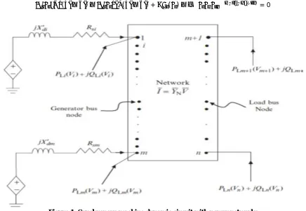
The power networks interconnect the synchronous machine with transmission and distribution nodes along with rest of the system components. The equivalent circuit of the power system networks together with stator networks of the synchronous machines and the active and imaginary power loads is presented in figure1. The network equations for an n number of bus systems were written in complex form studied in [10]
The network equations for the generator buses are given by
( − ) П + ( ) + ( ) = ( )
for i=1, 2, 3, . . ., m (number of generator buses). The network equation for the load buses is
( ) + ( ) = ( )
ISSN (Print) : 2320 – 3765 ISSN (Online): 2278 – 8875
I
nternational
J
ournal of
A
dvanced
R
esearch in
E
lectrical,
E
lectronics and
I
nstrumentation
E
ngineering
(An ISO 3297: 2007 Certified Organization) Vol. 5, Issue 10, October 2016
Here
( − ) П = ( ) + ( )
is the complex power “injected” into bus i due
to the generator.For the generator buses network equations are separated into real and imaginary parts and are represented in power balance form as
( − )− ( − ) + ( )− ( ) = 0
Figure 1: Synchronous machine dynamic circuit with power networks
where i=1, 2, 3, . . ., m for generator buses.m+1,m+2…….n are load buses now Linearization of the network equations that pertain to generator buses (PV buses) gives write in matrix form
( ( − )− ( − )) 0
− ( − ) +− ( − ) 0
0 0 0 0
∆ ∆
+ ( − ) − ( − )
( − ) − ( − )
∆ ∆ +
4( , )∆ + 5( , )∆
Here
D4(i, k), k=1, 2. . . m (for generator buses) : D5(i, k), k=m+1, m+2, . ,n (for non-generator buses).
i Vi
Vg iHere i=1, 2...m (for generator buses) and
i Vi
V1i Here
V
1
i i=m+1, m+2. . .n(for non-generator buses),
Now above equation in simple form for number of m machines
2∆ + 3∆ + 4( , )∆ + 5( , )∆ 1 = 0
for the m-machine system, the order of matrix 1 ∗ , 3 ∗ , Each machine matrix is diagonal elements of overall
ISSN (Print) : 2320 – 3765 ISSN (Online): 2278 – 8875
I
nternational
J
ournal of
A
dvanced
R
esearch in
E
lectrical,
E
lectronics and
I
nstrumentation
E
ngineering
(An ISO 3297: 2007 Certified Organization) Vol. 5, Issue 10, October 2016
matrix obtain linearization PV Bus equation with respect to all PV bus voltage and angle . D5 matrix obtains linearization PV Bus equation with respect to all PQ bus voltage and angle.
Linearization of the network equations that pertain to load buses (PQ buses)
( )− ( − − ) = 0
( )− ( − − ) = 0
Write in simple form
6( , )∆ + 7( , )∆ 1 = 0
Here order of 6 ∗ , 7 ∗ are full matrices
D6 matrix obtain linearization PQ Load equation with respect to all PV bus voltage and angle D7 matrix obtain linearization PQ Load equation with respect to all PQ bus voltage and angle Write all equation together
∆ = 1∆ + 1∆ + 2∆ + 1∆
0 = 1∆ + 1∆ + 2∆
0 = 2∆ + 3∆ + 4∆ + 5∆ 1
0 = 6∆ + 7∆ 1
Where
] ... 3 .. 2 .. 1
[X T XT XT XTM X
]
,
,
,
[
i
Wi
Edi
Efdi
Xi
]
,
...
2
,
2
,
1
,
1
[
V
V
m
Vm
Vg
]
,
...
2
,
2
,
1
,
1
[
1
n
Vn
m
V
m
m
V
m
V
Rearrange the above equation.
Write as =−( )∆ − ∆ into above equations
∆ = ( 1− )∆ + ( 2− )∆ + 1∆
0 = ( 4− )∆ + ( 2− )∆ + 5∆ 1
0 = 6∆ + 7∆ 1
Writing Equations Above in state-space representation
∆ 0 0
=
1− 2− 0
4− 2− 5
0 6 7
∆ ∆ ∆ 1
+
1 0 0
∆
This in more compact form written as
∆
0 =
∆
∆ +
1
0 ∆
= 1−
= 2−
= 2−
0
= 4− 5
ISSN (Print) : 2320 – 3765 ISSN (Online): 2278 – 8875
I
nternational
J
ournal of
A
dvanced
R
esearch in
E
lectrical,
E
lectronics and
I
nstrumentation
E
ngineering
(An ISO 3297: 2007 Certified Organization) Vol. 5, Issue 10, October 2016
Now
[ ]4 ∗4 = −[ ][ ] 1
2
This model can be used to examine the effect of small-signal disturbance on the Eigen values of the multi-machine power system. When a PSS or any FACTS devices are installed at any machine, the extra state variables corresponding to these controllers will be added with the system matrix.
IV.UPFC MODEL
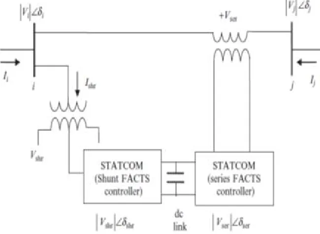
Unified power flow controller (UPFC) is one of the most advanced FACTS devices and is a combination of STATCOM and a SSSC[3]. UPFC was designed with two VSCs sharing a mutual capacitor on their dc side and a unified control system. The two devices are coupled through the dc link and the combination allows exchange of real power between the series SSSC and the shunt STATCOM. This controller (UPFC) has the facility to provide concurrent real and reactive series line compensation without any external electric energy source. Thus, UPFC is able to control real power flow, reactive power flow in a line, and the voltage magnitude at the UPFC terminals and may also be used as independently for shunt reactive compensation studied in[3,8].
The flow of active power for the series unit (SSSC) is obtained from the line itself through the shunt unit (STATCOM). STATCOM is used for voltage (or reactive power) control, while SSSC is utilized for real power control. UPFC is a complete FACTS controller for both active and reactive power flow controls in a line. The real power required for the series converter is drawn by the shunt converter from the ac bus (i) and supplied to bus j by the dc link. The inverted ac voltage ( ) at the output of SSSC is added to the sending end node voltage at line side to boost the nodal voltage at the bus. It may be noted here that the voltage magnitude of the output voltage | | provides voltage regulation, while the phase angle determines the power flow controlmode [11]. Additional
storage device through an electronic interface would provide the enhancement in capability of UPFC in active power flow control. In addition by providing a support in the real power exchange that takes place between the series converter and the ac system, the shunt converter may also generate or absorb reactive power in order to provide independent voltage regulation at its point of connection with the ac system[8,9].
ISSN (Print) : 2320 – 3765 ISSN (Online): 2278 – 8875
I
nternational
J
ournal of
A
dvanced
R
esearch in
E
lectrical,
E
lectronics and
I
nstrumentation
E
ngineering
(An ISO 3297: 2007 Certified Organization) Vol. 5, Issue 10, October 2016
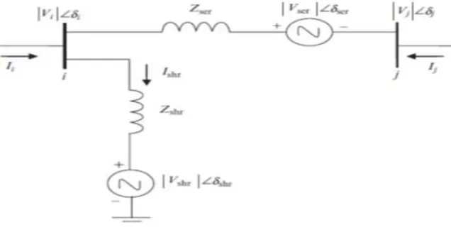
The UPFC equivalent circuit shown in figure2 consists of a shunt-connected voltage source and a series-connected voltage source. The active power constraint equation links the two voltage sources[3]. The two voltage sources are connected tothe ac system through inductive reactance representing the VSC transformers. The expressions for the two voltage sources and the constraint equation would be
=∣ ∣( + )
=∣ ∣( + )
(− + )
Here, and dshr are the controllable magnitude and the voltage source phase representing the shunt converter. The magnitude and phase angle of the voltage source represent the series converter. Similar to the shunt and series voltage sources used to represent the STATCOM and the SSSC, respectively, the voltage sources used in the UPFC application would also have control limits, i.e., < < ,0< <2pi and < < , 0< <2pi, respectively. The phase angle of the series-injected voltage determines the mode of power flow control.
Figure 3: Equivalent circuit of a UPFC between two buses i and j.
Based on equivalent circuit from figure 3
= ( − − ) + ( − )
= (− + + )
= 0 0
∗
∗ Here = +j simply the equation
The real and imaginary at and end
= + ( − ) + ( − ) + ( ( − ) + ( − )
+ ( ( − ℎ ) + ( − ℎ ))
= + ( − ) + ( − ) + ( ( − ) + ( − )
=− + ( − )− ( − ) + ( ( − )− ( − )
ISSN (Print) : 2320 – 3765 ISSN (Online): 2278 – 8875
I
nternational
J
ournal of
A
dvanced
R
esearch in
E
lectrical,
E
lectronics and
I
nstrumentation
E
ngineering
(An ISO 3297: 2007 Certified Organization) Vol. 5, Issue 10, October 2016
=− + ( − ) + ( − ) + ( ( − )− ( − )
The UPFC power equations, in liberalized form, are combined with those of the ac network. In order to get the linearized model of the system using power mismatch form, let us assume UPFC is connected to node i and the power system is connected to node j. UPFC is required to control voltage at the shunt converter terminal, node i, and active power flows from node j to node i
.
The non-linear dynamic model of the system using UPFC is given below. IEEE-ST1static excitation system is considered studied in [9]= 0.75 ( ℎ)∗( ℎ ) + (sin( ℎ)∗ ℎ )) + ( )∗ ) + (sin( ℎ)∗ ))
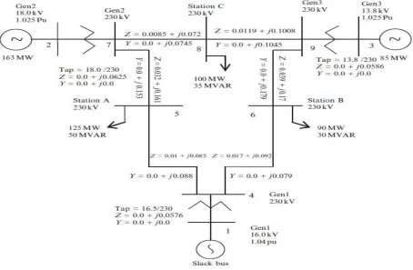
V.MATHMATICAL ANAYLSIS: WSCC TYPE 3-MACHINE, 9-BUS SYSTEM
Participation factor is a tool for identifying the state variables that have significant participation in a selected mode among many modes in a multi generator power system [5].
The standard IEEE 3 Machine 9 Bus system taken from literature[4]
Figure 4: WSCC Type 3-Machine, 9-Bus System
ISSN (Print) : 2320 – 3765 ISSN (Online): 2278 – 8875
I
nternational
J
ournal of
A
dvanced
R
esearch in
E
lectrical,
E
lectronics and
I
nstrumentation
E
ngineering
(An ISO 3297: 2007 Certified Organization) Vol. 5, Issue 10, October 2016
dimension and scaling associated with the state variables. As a solution of this problem, a matrix called the participation matrix (P) is suggested in which the right and left eigenvectors entries are combined, and it is used as a measure of the association between the state variables and the modes
Here
= [ 1, 2 … . ] =
⎣ ⎢ ⎢ ⎢ ⎡ 12
. . 3⎦
⎥ ⎥ ⎥ ⎤
=
⎣ ⎢ ⎢ ⎢
⎡∅1∅2 ∅∅ 12
. . ∅3 ∅ 3⎦
⎥ ⎥ ⎥ ⎤
kp
is the element on the row and column of the modal matrix,
is the entry of the right eigenvectorpk
p
,
is the element on the row and column of the modal matrix, and C is the entry of the left Eigen vector. The elementPkp
kp
pk
is termed the participation factor[12].From Participation factor it was found that at the generator 2 had a lowest damping ratio,so the controller (UPFC) placed in between at generator 2 to line 7.Now UPFC effects on PV bus (2) and PQ bus (7). That on multi machine it effects on D4, D5, D6, D7,B1, B2 matrixes and A12.Now linearization the static excitation of UPFC equation. The systematic matrix includes UPFC static excitation equation then order is increased by one .now order is (4m+1)*(4m+1). For 3 machine 9 bus system new order of system matrix is 13 × 13 the linearization of UPFC process seen in appendix.
From the UPFC power load flow equation(both Active and Reactive power equation) put i=2 j=7 and linearization done with respect
i
,
Vi
Load flow at bus 2 linearization done with respect Ɵ , include in D4 matrix. Load flow at bus 2 linearization done with respect Ɵ , include in D5 matrix Load flow at bus 7 linearization done with respect Ɵ , include in D6 matrix Load flow at bus 7 linearization done with respect Ɵ , include in D7 matrix
All these equation includes, and measurement the UPFC parameter now new Eigen value include UPFC
VI.RESULT AND DISCUSSION
In this paper discuss analysis of Multi machine system by linearization process which including two axis model of synchronous generator ,stator algebraic equation, generator equation and PQ equations and the analysis of UPFC on power system load flows. Stability had done by using state matrix representation form. By forcibly the system is under driven in to unstable, and then by using participation factor location of lowest damping factor is found. Then UPFC are to be fixed at machine then observe the stability increase from unstable to stable region.
EIGEN. VALUE WITH OUT UPFC EIGEN VALUE WITH UPFC -0.9699 +18.5135i
-0.9699 -18.5135i -1.0405 + 9.1857i -1.0405 - 9.1857i -1.5762 + 3.4923i -1.5762 - 3.4923i
1.4374 -1.6759 + 1.9202i
-1.6759 - 1.9202i -1.4293 + 0.1750i -1.4293 - 0.1750i
-1.0292
ISSN (Print) : 2320 – 3765 ISSN (Online): 2278 – 8875
I
nternational
J
ournal of
A
dvanced
R
esearch in
E
lectrical,
E
lectronics and
I
nstrumentation
E
ngineering
(An ISO 3297: 2007 Certified Organization) Vol. 5, Issue 10, October 2016
APPENDIX MACHINE DATA
Parameters Machine #1 Machine #2 Machine #3
(pu) H (s) D (pu)
(pu) (pu) (pu) (pu) (s)
(s)
0.089 23.64 0.2 0.269 0.0608 0.0969 0.0969 8.96 0.31
0.089 6.4 0.2 0.8958 0.1198 0.8645 0.8645 6.0 0.535
0.089 3.01
0.2 1.998 0.1813 1.2578 1.2578 5.89
0.6
Exciter Data
Parameters Machine #1 Machine #2 Machine #3
KA TA TE(S) KE(S)
20 0.2 0.314
1
20 0.2 0.314
1
20 0.2 0.314
1 UPFC PARAMETER:
DC LINK: =10; =0.0; =2 =131.5, =0.193 :52.76
REFERENCES
[1]P.Kundur, “Power System Stability and Control,”McGraw-Hill, New York,1994
[2] P. M.Anderson, A.A.Fouad,”Power System Control and Stability,” Iowa State University Press, AMES, IOWA, U.S.A 1977
[3] Gyugyi, L.; , "Unified power-flow control concept for flexible AC transmission systems," Generation, Transmission and Distribution, IEEE Proceedings C, vol.139, no.4, pp.323-331, Jul 1992
[4] Enhancing Stability of Multi-Machine IEEE 9 Bus Power System Network Using PSS BYDivyaPrakashVinay Kumar Tripathi International Journal of Advanced Research in Electrical, Electronics and Instrumentation Engineering Vol. 4, Issue 5, May 2015
[5]” Power System Stabilizer for Stability Improvement of Power System” by Bhumika, JitendraKasera International Journal of Engineering and Technical Research (IJETR) ISSN: 2321-0869, Volume-2, Issue-6, June 2014
[6] Hingorani, N.G.; , "FACTS-flexible AC transmission system," AC and DC Power Transmission, 1991., International Conference on , vol., no., pp.1-7, 17-20 Sep 1991
[7] Gyugyi, L.; Schauder, C.D.; Williams, S.L.; Rietman, T.R.; Torgerson, D.R.; Edris, A.; , "The unified power flow controller a new approach to power transmission control," Power Delivery, IEEE Transactions on , vol.10, no.2, pp.1085-1097, Apr 1995
[8] Padiyar, K.R.; Kulkarni, A.M.; , "Control design and simulation of unified power flow controller," Power Delivery, IEEE Transactions on , vol.13, no.4, pp.1348-1354, Oct 1998
[9] Tambey, N.; Kothari, M.L.; , "Damping of power system oscillations with unified power flow controller (UPFC)," Generation, Transmissionand Distribution, IEE Proceedings- , vol.150, no.2, pp. 129- 140, March 2003
[10]Linearisation of multi-machine power system: Modeling and control – A survey by N. Yadaiah N. VenkataRamana Electrical Power and Energy Systems in science direct ELSEVIER 29 (2007) 297–311
[11] MAKOMBE. T., and JENKINS, N.: 'Investigation of a unified power flow controller'. IEEE generation transmission distribution 1999 146(4) pp.400-40