METHOD OF LARGEST EXTENDED CIRCLE FOR THE CAPACITANCE OF ARBITRARILY SHAPED
CONDUCTING PLATES
C. H. Liang, H. B. Yuan, and K. B. Tan
Xidian University Xi’an 710071, China
Abstract—The most difficult step in the analysis of the capacitance of arbitrarily shaped conductingplates is the determination of the electric center, or the expansion point of the charge density. This paper presents the generalized Huygens’ principle, which indicates that the charge distribution on a conducting plate of convex shape has a tendency to be a circle before approachingthe fringe. Therefore, the center of the largest extended circle can be taken as the electric center. The agreement with numerical methods is demonstrated.
1. INTRODUCTION
With the quick development of microwave communication, the line between the technique of wave and the technique of circuit becomes more and more obscure in engineering. We can not only add some lumped elements to a distributed parameter filter, but also consider distributed parameters in a lumped element system. Therefore, the capacitance of conductingplates and the inductance of conducting wires of arbitrary shape attract many scholars’ attention.
Two problems arise from the determination of the closed form for the capacitance of the conductingplate. One is the charge distribution on the plate, and another is the optimal expansion center of the charge density, or what is called the electric center.
Reference [1] take a disc whose analytic results has been obtained as an example. Considering that the charge density on the edge of the disc is a singular distribution, namely
σ(r) = σ0 1−(r/r0)2
x
y z
o
0 r
Figure 1. Infinitely thin conductingdisc.
x
y
o
0
r ϕ
1 ) ( 0 S ϕ =
r
Figure 2. Symmetrical convex conductingplate.
We can obtain the accurate capacitance.
C0 = Q
V = 8ε0r0=
2r0
9π ·10
−9F (2)
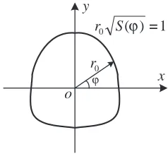
For a general symmetric conducting plate, the boundary curve equation can be introduced. It is
r0
S(ϕ) = 1 (3)
And then the charge density is expanded at the symmetric center, so we have
σ(r, ϕ) = σ0
1−r2S(ϕ) (4)
Finally, the closed form of the capacitanceC is
C = Q
V = 8ε0
π
2
0 dϕ S(ϕ)
π
2
0
dϕ
Applyingformula (5) to an elliptical disc, in which
S(ϕ) = cos
2ϕ a2 +
sin2ϕ
b2 (6)
and b > a is supposed. So the capacitance of an elliptical disc is
C= 4πε0a
K(k) ·
b a
F (7)
in which K(k) represents the complete elliptical functions of the first kind with modulusk, and
k= √
b2−a2
b (b > a) (8)
Formula (7) is also an accurate result by [2].
2. SELECTION OF THE ELECTRIC CENTER
The success of a closed form lies mainly in the fact that the assumed singular distribution of the charge density is in accordance with the practical distribution. However, the determination of the electric center remains to be a problem. Different electric center may lead to different results.
x y
o
0
r a
0
x
ϕ
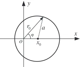
Figure 3. Disc with eccentric center.
Figure 3 shows a conducting plate expanded at an eccentric center. And the equation of which is
(x−x0)2+y2 =a2 (9) Another equation can be obtained by normalized polar coordinate. It is
in which ¯r0 =r0/aand ¯x0 =x0/aare normalized values. Note that ¯r0
andr0 are both on the fringe of the disc. So the function of the charge
density of the disc is
σ(r, ϕ) = σ0
1−(¯x0sinϕ)2−(r−x0¯ cosϕ)2
= σ0
1−(¯x0sinϕ)2
1− ¯r−¯x0cosϕ
1−(¯x0sinϕ)2 2
(11)
in which r is a variable andr ≤r0.
In this case, the original quarter symmetry of the disc has turned to be a half even symmetry, and the potentialV at the eccentric center
O is
V = 2σ0a 4πε0
π
0 dϕ
√(¯r0−x¯0 cosϕ) 1−(¯x0 sinϕ)2
0
du
√
1−u2 = πaσ0
4ε0
(12)
Note that (¯r0 − x¯0cosϕ) =
1−(¯x0sinϕ)2 has been taken into
account in the derivation process of the formula above. Besides, the total chargeQis
Q = 2a2σ0
π 0
dϕ
r¯0
0
¯
rdr¯
1−(¯x0sinϕ)2
1− (¯r−x¯0cosϕ)
1−(¯x0sinϕ)2 2
= 2a2σ0
π
0
1−(¯x0sinϕ)2dϕ+
π 0
¯
x0cosϕdϕ
1
0 du
√ 1−u2
(13)
= 4a2σ0E(¯x0)
in which E(¯x0) is the complete elliptical integral of the second kind
with modulus ¯x0.
Finally, the capacitance of the disc expanded at the eccentric center is
C = Q
V = 8ε0a
E(¯x0)
π/2
F (14)
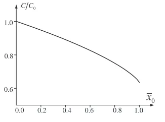
Figure 4 shows the functional relationship of the normalized capacitance ¯C = C/C0 with the modulus ¯x0, in which C0 = 8ε0a
is the capacitance obtained by expandingthe charge at the center of the disc.
The example forcefully demonstrates that the determination of the electric center is of great importance. It is proved that the capacitance is variational standingfor the charge test function. Proper electric center could lead to
0
C C
0
x 0
.
0 0.2 0.4 0.6 0.8 1.0 0
. 1
8 . 0
6 . 0
Figure 4. Relationship of capacitance ¯C=C/C0 with ¯x0.
For symmetric objects like the disc, the geometrical center coincides with the electric center. However, new methods for choosing electric center must be given for objects of arbitrary shape.
3. LARGEST EXTENDED CIRCLE METHOD
Huygens’ principle is of special importance in electromagnetism. There are two wonderful ideas. One is that every point at the wavefront has wavelets. Another is that every wavelet transmits spherical waves outwards. Huygens’ principle implies the most important idea, that is, waves have a tendency to be a sphere, cylinder or circle without the restriction of the boundary conditions.
In [3], Huygens’ principle is advanced further and generalized Huygens’ principle is introduced. It means that the charge distribution on a conductingplate tends to be concentric circles before reachingthe edge.
Whether be static field or dynamic field, wave or non-wave, this property can be termed as electromagnetic inertia, just as Newton’s mechanic inertia.
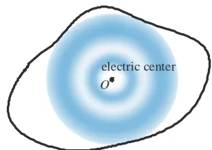
Therefore, we can put forward the selectingprinciple of the electric center of a convex edged conducting plate. The electric center of a convex edged conducting plate should be the center of its largest extended circle, as shown in Figure 5.
This method can satisfy the free state of the charge distribution, or beingconcentric circles, as much as possible.
4. EXAMPLES
O
electric center
Figure 5. Center of largest extended circle.
A
B
C
D
E
F
o
r
r
r
1
r r2
3 r
Figure 6. Arbitrary triangle plate.
r is the radius of the encircle. Let
x=BD=BF y=CD=CE z=AE =AF
(16)
∆ represents the area of the triangle, and the basic geometrical relations is shown in Table 1.
If the center of the encircle is taken as the expansion center, the triangle ∆ABC can be divided into three basic triangles, ∆OAB, ∆OBC and ∆OCA.
In which AB, BC and AC are the edges of the plate. The capacitance of ∆ABC is
C=
3
i=1 Qi
3
i=1
Vi (17)
in which Qi and Vi represent the charge and potential of the ith
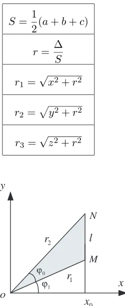
Table 1. Basic geometrical relations in a triangle.
S= 1
2(a+b+c)
r = ∆
S r1 =
√
x2+r2
r2 =
y2+r2
r3=√z2+r2
x o
y
l
M
N
2
r
1
r
1 ϕ 0 ϕ
0
x
Figure 7. Basic triangle M ON.
Under this condition the charge distribution function expanded at point O is
σ(r, ϕ) = σ0 1−xx
0 2 =
σ0
1−rcosx ϕ 0
2 (18)
and the potentialVi of the ∆OM N at the center is Vi =
1 4πε0
ϕ1+ϕ2
ϕ1
dϕ
r0
0
σ0dr
1−rcosx ϕ 0
2
= σ0x0 8ε0
1 2ln
1−sinϕ1
1 + sinϕ1 ·
1 + sin(ϕ1+ϕ0)
1−sin(ϕ1+ϕ0)
in which,
sinϕ1 = r2cosϕ0−r1
l
sin(ϕ1+ϕ0) = r2−r1cosϕ0
l
tanϕ1=
r2cosϕ0−r1 r2sinϕ0
tan(ϕ1+ϕ0) =
r2−r1cosϕ0 r1sinϕ0
(20)
On account of
cosϕ0 =
r21+r22−l2
2r1r2
(21)
1 2ln
1−sinϕ1
1 + sinϕ1 ·
1 + sin(ϕ1+ϕ0) 1−sin(ϕ1+ϕ0)
= ln
r1+r2+l r1+r2−l
(22)
that is
Vi = σ0x0
8ε0
ln
r1+r2+l r1+r2−l
(23)
Similarly, the chargeQi of the ∆M ON is
Qi =
ϕ1+ϕ0
ϕ1 dϕ r0 0 σr 1−
rcosϕ x0
2 dr
=σ0r1r2sinϕ0
(24)
in which
x0 = r1r2sinϕ0
l (25)
In the original triangle ABC, considering x0 equals the radius of the encircle and formula (17), the capacitance of the triangle ∆ABC is
C = 8ε0(a+b+c) lnr1+r2+a
r1+r2−a
+ lnr2+r3+b
r2+r3−b
+ lnr3+r1+c
r3+r1−c
(26)
Formula (26) represents the capacitance of the conductingplate with the center of the encircle of the triangle as the electric center. Table 2 shows the comparison of the capacitances of the triangles obtained by formula (26) and by the moment method [3–6]. It demonstrates that the relative error is less than 3%.
Note that there are more than one largest extended circle for some plates of arbitrary shape. In this case, a more symmetric center should be adopted. Take the parallelogram conducting plate ABCD
Table 2. Comparison of capacitances of different triangles by two methods.
Different triangles
Incircle electric center
a C/8 0
Moment
a C/8 0
Relative error
0 0
C C C C
A
C B
45 45
a a
a 2
0.41524 0.42797 -0.02975
A
B 45 60 C
75
a
2 2 33a
a
) 3 3 1 (
0.51670 0.53054 -0.02609
A
B C
45
15
120
a 2
a 3 3 2
a ) 3 3 1 (
0.30593 0.31500 -0.02877
=
-ε
ε
+
-Method
δ
o o
o
o o
o
o o
A
C
D
B
a a
5 . 1
O
Figure 8. Largest extended circle of parallelogram.
the one whose center is in accordance with the symmetric center O
should be adopted. Similarly we lead to
C0 = 0.62935·8ε0a δC=−1.950%
and the two values are in good agreement with each other.
5. CONCLUSION
The difficulty to determine the closed form of the capacitance of a conductingplate of arbitrary shaped lies mainly in the selection of the electric center, or the charge expansion point.
In this paper, generalized Huygens’ principle that the charge distribution has a tendency to be concentric circles as much as possible is introduced. Therefore, it is proper to take the center of the largest extended circle as the electric center. And it is fully proved by the practical examples.
REFERENCES
1. Liang, C. H., L. Li, and H. Q. Zhi, “Asymptotic closed form for the capacitance of an arbitrarily shaped conductingplate,” IEE Proc.-Microw. Antennas, Vol. 151, No. 3, 217–220, June 2004. 2. Stratton, J. A.,Electromagnetic Theory, McGraw-Hill, New York,
1941.
3. Harrington, R. F., Field Computation by Moment Methods, IEEE Press, New York, 1993.
4. Cheng, D. K. and C. H. Liang, “Thinning technique for moment method solutions,”Proc. IEEE, Vol. 71, No. 2, 265–266, 1983. 5. Bancroft, R., “A note on the moment method solution for the
capacitance of a conductingflat plate,” IEEE Trans. Antennas Propag., Vol. 45, No. 11, 1704, 1997.
6. Kuo, J. T. and K. Y. Su, “Analytical evaluation of the mom matrix elements for the capacitance of a charged plate,” IEEE Trans. Microw. Theory. Tech., Vol. 50, No. 5, 1435–1436, 2002.
7. Collin, R. E., Field Theory of Guided Waves, McGraw-Hill, New York, 1960.
8. Shumpert, T. H. and D. J. Galloway, “Capacitance bounds and equivalent radius,”IEEE Trans. Antennas Propag., Vol. 25, No. 2, 284–286, 1977.