Electronic Thesis and Dissertation Repository
4-20-2012 12:00 AM
Photocatalytic Reactors for Air Treatment: Energy Efficiencies and
Photocatalytic Reactors for Air Treatment: Energy Efficiencies and
Kinetic Modeling
Kinetic Modeling
Juan M. Garcia Hernandez The University of Western Ontario Supervisor
Hugo de Lasa
The University of Western Ontario
Graduate Program in Chemical and Biochemical Engineering
A thesis submitted in partial fulfillment of the requirements for the degree in Doctor of Philosophy
© Juan M. Garcia Hernandez 2012
Follow this and additional works at: https://ir.lib.uwo.ca/etd
Part of the Catalysis and Reaction Engineering Commons
Recommended Citation Recommended Citation
Garcia Hernandez, Juan M., "Photocatalytic Reactors for Air Treatment: Energy Efficiencies and Kinetic Modeling" (2012). Electronic Thesis and Dissertation Repository. 459.
https://ir.lib.uwo.ca/etd/459
This Dissertation/Thesis is brought to you for free and open access by Scholarship@Western. It has been accepted for inclusion in Electronic Thesis and Dissertation Repository by an authorized administrator of
(Spine title: Photocatalytic Reactors for Air Treatment)
(Thesis format: Monograph)
by
Juan Manuel Garcia Hernandez
Graduate Program in Chemical and Biochemical Engineering
A thesis submitted in partial fulfillment of the requirements for the degree of
Doctor of Philosophy
The School of Graduate and Postdoctoral Studies The University of Western Ontario
London, Ontario, Canada
ii
CERTIFICATE OF EXAMINATION
Supervisor
______________________________ Dr. Hugo de Lasa
Supervisory Committee
______________________________ Dr. Benito Serrano
______________________________
Examiners
______________________________ Dr. Ajay K. Ray
______________________________ Dr. Charles Xu
______________________________ Dr. Fariborz Taghipour
______________________________ Dr. Ron R. Martin
The thesis by
Juan Manuel Garcia Hernandez
entitled:
Photocatalytic Reactors for Air Treatment: Energy Efficiencies
and Kinetic Modeling
is accepted in partial fulfillment of the requirements for the degree of
Doctor of Philosophy
______________________ _______________________________
iii
Indoor air pollution is an increasing environmental concern. Heterogeneous
photocatalysis is a promising strategy for the elimination of air pollutants in enclosed environments. However, studies involving gas-phase heterogeneous photocatalysis are relatively few compared with the substantial literature on photocatalytic water
treatment.
It is necessary to pay special attention to the photocatalytic reactor design allowing for optimal use of irradiation. Therefore, in addition to the rate of photoconversion, an energy yield describing the light utilization efficiency and how this energy efficiency varies at different operating conditions should de defined. A parameter for this analysis is the quantum efficiency. This parameter can also help in reaction pathway
discrimination.
Definitions of quantum yields should be based on ratios involving photoconverted molecules over the rate of light intensity absorbed at a given wavelength. Although determining the rate of light intensity absorbed at a given wavelength is a relative easy task in homogeneous systems, it is a rather difficult assignment for heterogeneous reactions. In this case, light is not only absorbed but also scattered and reflected by the suspended semiconductor particles.
iv required by thermodynamics.
Keywords
v
support, encouragement, criticism and patience during the development of this project.
I would also like to thank Professor Benito Serrano for all his suggestions, comments and useful advice.
I am grateful to the CREC staff, members and colleagues. It has been a pleasure to share with you and learn from all of you.
My sincere appreciation goes to the administrative staff in the Department of Chemical and Biochemical Engineering, the University Machine Services, people at The
University of Western Ontario that helped me in the completion of my PhD program and those I forgot between the pages.
I offer my gratitude to The National Council of Science and Technology in Mexico (CONACyT-México) for the scholarship provided.
I am indebted to my close friends, old and new. They are by my side when going through happy and difficult moments equally, regardless distance and time.
vi
CERTIFICATE OF EXAMINATION ...ii
Abstract ... iii
Acknowledgments ...v
Table of Contents ...vi
List of Tables ...x
List of Figures ...xi
List of Appendices ...xv
Nomenclature ...xvi
Chapter 1 ...1
1 Introduction ...1
Chapter 2 ...4
2 Literature Review ...4
2.1 Introduction ...4
2.2 Heterogeneous Photocatalysis ...4
2.3 Photocatalysts ...5
2.3.1 TiO2 Photocatalysts ...6
2.4 Photocatalytic Reactors and Light Sources ...7
2.4.1 Honeycomb Monolith Reactors...7
2.4.2 Fluidized Bed Reactors...8
2.4.3 Annular Reactors ...10
2.4.4 Packed bed Reactors ...11
2.4.5 Fibre Optic Based Reactors ...12
2.4.6 Light sources ...13
2.5 Photo-CREC-Air Reactors ...15
vii
2.6 Energy Efficiencies in Photocatalytic Reactors ...20
2.6.1 Quantum Yields ...21
2.6.2 Photochemical Thermodynamic Efficiency Factor (PTEF) ...23
2.7 Photocatalytic Kinetics Models ...24
2.8 Conclusions ...26
Chapter 3 ...27
3 Scope of the Research ...27
3.1 General Objectives of the Research ...27
3.2 Specific Objectives of the Research ...28
3.2.1 Photocatalyst Preparation and Kinetic Studies ...28
3.2.2 Irradiation and Flow Field Studies ...28
3.2.3 Energy Efficiency Evaluation ...29
Chapter 4 ...30
4 Experimental Setup ...30
4.1 Introduction ...30
4.2 Photo-CREC-Air Reactor ...30
4.3 UV Sources ...34
4.4 Photocatalyst Support ...35
4.5 Photocatalyst Impregnation ...38
4.6 Irradiation Field Analysis ...38
4.7 Flow Field Analysis ...41
4.8 Conclusions ...43
Chapter 5 ...44
5 Experimental Methods ...44
5.1 Sample Analysis ...44
viii
Chapter 6 ...49
6 Results and Discussion I: Kinetic Modeling ...49
6.1 Introduction» ...49
6.2 Photocatalysis Kinetics Modeling ...49
6.3 Acetone Photocatalytic Degradation Modeling ...52
6.4 Acetaldehyde Photocatalytic Degradation Modeling ...55
6.5 Isopropanol Photocatalytic Degradation Modeling ...58
6.6 Conclusions ...64
Chapter 7 ...65
7 Results and Discussion II: Energy Efficiencies in Previous Versions of the Photo-CREC-Air Reactor ...65
7.1 Introduction ...65
7.2 Quantum Efficiency in Previous Photo-CREC-Air Reactor Versions ...65
7.3 Photochemical-Thermodynamic Efficiency Factor (PTEF) in Previous Photo-CREC-Air Reactor Versions ...69
7.4 Conclusions ...72
Chapter 8 ...73
8 Results and Discussion III: Energy Efficiency in the 55.1 L Version of the Photo-CREC-Air Reactor ...73
8.1 Introduction ...73
8.2 Energy Efficiency Factors ...74
8.3 Stoichiometric Equations and Photoreaction Rates ...77
8.3.1 Acetone Photocatalytic Degradation Stoichiometry ...78
8.3.2 Acetaldehyde Photocatalytic Degradation Stoichiometry ...78
8.3.3 Isopropanol Photocatalytic Degradation Stoichiometry ...79
8.4 Photocatalytic Modeling ...79
ix
8.5 Energy Efficiency Calculations ...90
8.6 Conclusions ...97
Chapter 9 ...98
9 Conclusions and Recommendations ...98
9.1 Main Conclusions ...99
9.2 Recommendations for Future Work ...99
References ...101
Appendices ...112
x
Table 1: Bandgap energy of various photocatalysts...6
Table 2: Properties and features of the artificial UV light sources ...15
Table 3: Quantum Parameter Definitions...22
Table 4: Kinetic and Data Modeling Parameters for acetone photocatalytic degradation with Degussa P25 photocatalyst...81
Table 5: Kinetic and Data Modeling Parameters for acetaldehyde photocatalytic
degradation with Degussa P25 photocatalyst ...85
Table 6: Kinetic and Data Modeling Parameters for isopropanol photocatalytic
degradation with Degussa P25 photocatalyst ...90
xi
Figure 1: Schematic of the Processes that take place when a semiconductor particle
receives band-gap illuminated ...5
Figure 2: Schematic diagram of the monolith reactor ...8
Figure 3: Schematic diagram of the fluidized-bed reactor ...9
Figure 4: Schematic diagram of the annular reactor ...10
Figure 5: Photocatalytic reactors used by Esterkin et al., (2002) ...12
Figure 6: Schematic diagram of the optical fiber photocatalytic ...13
Figure 7: Schematic diagram of the Former Photo-CREC-Air reactor ...17
Figure 8: Former Version of the Photo-CREC–air Venturi section ...18
Figure 9: Picture of Photo-CREC-Air Reactor showing its main components. The protecting enclosure holding the 8 near UV lamps is open for a better description of Photo-CREC-Air components ...31
Figure 10: Detailed drawing of the Photo-CREC-Air Reactor dimensions ...32
Figure 11a: Diagram of the Photo-CREC-Air Reactor, isometric view ...33
Figure 11b: Description of the Venturi divergent section in the Photo-CREC-Air Reactor ...33
Figure 12: Detail of the reaction section in the Photo-CREC-Air Reactor showing the near-UV lamps distributed circumferentially around the reaction section ...35
Figure 13: Cylindrical mesh used as catalyst support ...36
Figure 14: Stainless steel mesh cylinder coated with Degussa P25 ...37
xii
Figure 17: Schematics of the specially designed Periscopic Irradiation Receiver
showing the angle of acceptance ...40
Figure 18a: Schematic Diagrams of the Periscope Irradiation Receiver showing the irradiation acceptance angle placed at three positions: Periscope placed between the
glass tube and the near UV lamps measuring “Pe” ...41
Figure 18b: Schematic Diagrams of the Periscope Irradiation Receiver showing the irradiation acceptance angle placed at three positions: Periscope placed between the
impregnated mesh and the glass tube measuring “Pe1” ...41
Figure 19: Schematic Diagram and Description of air circulation in Photo-CREC-Air
Reactor ...42
Figure 20: Cross Flow sensor probe and support (TSI Inc.) used to measure the velocity inside the reaction section ...43
Figure 21: GC temperature program used for the experiments ...44
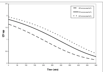
Figure 22: QYapp for acetone using experimental data reported by Ibrahim and de Lasa
(2004) with the catalyst Hombikat UV-100. Three initial concentrations in μmol/L: 40, 50 and 60 ...66
Figure 23: QYapp for acetone using experimental data reported by Ibrahim and de Lasa
(2004) with the catalyst Degussa P25. Three initial concentrations in μmol/L: 40, 50 and 60 ...67
Figure 24: QYapp for acetaldehyde using experimental data reported by Ibrahim and de
Lasa (2004) with the catalyst Hombikat UV-100. Three initial concentrations in μmol/L: 30, 40 and 50 ...67
Figure 25: QYapp for acetaldehyde using experimental data reported by Ibrahim and de
xiii
40, 50 and 60 ...70
Figure 27: PTEFapp for acetone using experimental data reported by Ibrahim and de
Lasa (2004) with the catalyst Degussa P25. Three initial concentrations in μmol/L: 40, 50 and 60 ...70
Figure 28: PTEFapp for acetaldehyde using experimental data reported by Ibrahim and
de Lasa (2004) with the catalyst Hombikat UV-100. Three initial concentrations in
μmol/L: 30, 40 and 50 ...71
Figure 29: PTEFapp for acetaldehyde using experimental data reported by Ibrahim and
de Lasa (2004) with the catalyst Degussa P25. Three initial concentrations in μmol/L:
30, 40 and 50 ...71
Figure 30: Changes of acetone concentrations with reaction time using the Degussa P25 as catalyst. Three initial concentrations in μmol/L were considered: 49(◊), 37(Δ) and
24.5(ο). (Continuous line represents model predictions using Equation 19) ...82
Figure 31: Changes of CO2 concentrations with reaction time during the photocatalytic
degradation of acetone using the Degussa P25 as catalyst. Three initial concentrations of acetone in μmol/L were considered: 49(◊), 37(Δ) and 24.5(ο). (Continuous line
represents model predictions) ...83
Figure 32: Changes of acetaldehyde concentrations with reaction time using Degussa P25 as catalyst. Three initial concentrations in μmol/L were considered: 320(◊), 240(Δ) and 160(ο). (Continuous line represents model predictions using Equation 22) ...85
Figure 33: Changes of CO2 during the photocatalytic degradation of acetaldehyde using
Degussa P25 as catalyst. Three initial concentrations of acetaldehyde in μmol/L were
considered: 320(◊), 240(Δ) and 160(ο). (Continuous line represents model predictions) ...86
xiv
Figure 36: PTEF for acetone using Degussa P25 as photocatalyst. Three initial
concentrations were considered in μmol/L: 49, 37 and 24.5 ...92
Figure 37: QY for acetaldehyde using Degussa P25 as photocatalyst. Three initial
concentrations in μmol/L: 320, 240 and 160 ...93
Figure 38: PTEF for acetaldehyde using Degussa P25 as photocatalyst. Three initial
concentrations in μmol/L: 320, 240 and 160 ...93
Figure 39: QY for isopropanol using Degussa P25 as photocatalyst. Three initial
concentrations in μmol/L: 200, 150 and 100 ...95
Figure 40: PTEF for isopropanol using Degussa P25 as photocatalyst. Three initial
concentrations in μmol/L: 200, 150 and 100 ...95
Figure C1: Spectral intensity of a new Pen-Ray lamp as measured by the Sola Scope
2000 Spectroradiometer (Ibrahim, 2001) ...117
Figure D1: Spectral intensity inside the reaction section of the Photo-CREC-Air reactor reporting the fraction of the total energy involved in the average photon energy
calculation ...120
Figure E1: Spectral intensity for a new 15 W black-light-bulb near-UV lamp as
measured with the spectrophotometer Stellarnet EPP2000 ...122
Figure E2: Typical lamp axial radiation flux as measured at the surface of the
photocatalyst support ...123
Figure E3: Spectral intensity profiles for three locations in the axial direction of the
xv
Appendix A: Mechanism of Formation of OH• Radicals in Photocatalytic Processes for
Air Treatment ...112
Appendix B: Reaction Enthalpy for the Formation of OH• Radicals in Photocataltyic
Reactors for Air Treatmentt...114
Appendix C: Calculation of the Average Photon Energy and the Fraction of Qirr with a
Wavelength Smaller than 388 nm (14.7 L Photo-CREC-Air Unit) ...116
Appendix D: Calculation of the Average Photon Energy and the Fraction of Qadswith a
Wavelength Smaller than 388 nm (55.1 L Photo-CREC-Air Unit) ...119
xvi
Airr irradiated mesh area holding the catalyst, m2
c speed of light in vacuum, m s-1
C concentration, μmol m-3
Ci concentration of i species, μmolm-3
Cj concentration of j species, μmolm-3
T DE ACETALDEHY
C , total concentration of acetaldehyde, μmol/L
T ACETONE
C , total concentration of acetone, μmol
T L ISOPROPANO
C , total concentration of isopropanol, μmol
CS0 dimensionless Langmuir parameter
av
E average energy of a photon, J
)
(λ
E energy of a photon at a given wavelength, J
h Planck’s constant J s photon-1
)
(λ
I intensity of light, W cm-2
DE ACETALDEHY
k reaction rate constant for acetaldehyde, μmol m-3 min-1
ACETONE
k reaction rate constant for acetone, μmole m-3 min-1
L ISOPROPANO
k reaction rate constant for iopropanol, μmole m-3 min-1
ki intrinsic kinetic constant for i species, μmol m-3 min-1 k1 reaction rate constant of the first reaction involved in the
xvii
kleak parameter accounting pollutant leak, m-3 min-1
K adsorption constant
KiA adsorption constant for i species, m3μmol-1
KjA adsorption constant for j species, m3μmol-1
DE ACETALDEHY A
K acetaldehyde adsorption constant, m3μmol-1
ACETONE A
K acetone adsorption constant, m3μmol-1
LE ISOPROPANO A
K isopropanol adsorption constant, m3μmol-1
DE ACETALDEHY
K′ dimensionless acetaldehyde adsorption constant
ACETONE
K′ dimensionless acetone adsorption constant
L ISOPROPANO
K′ dimensionless isopropanol adsorption constant
g DE ACETALDEHY
C , concentration of acetaldehyde in the gas phase, μmol m -3
g ACETONE
C , concentration of acetone in the gas phase, μmol m-3
g L ISOPROPANO
C , concentration of isopropanol in the gas phase, μmol m -3
T DE ACETALDEHY
N , total number of moles of acetaldehyde
T ACETONE
N , total number of moles of acetone
T L ISOPROPANO
N , total number of moles of isopropanol
g DE ACETALDEHY
N , number of moles of acetaldehyde in the gas phase
g ACETONE
xviii
s DE ACETALDEHY
N , number of moles of acetaldehyde adsorbed on the solid
s ACETONE
N , number of moles of acetone adsorbed on the solid
s L ISOPROPANO
N , number of moles of isopropanol adsorbed on the solid
Pe rate of photons emitted by the lamps
Pe1 rate of photons reaching the photocatalyst surface
Pt rate of photons not absorbed by the photocatalyst
DE ACETALDEHY
q amount of acetaldehyde adsorbed, μmol g-1
ACETONE
q amount of acetone adsorbed, μmol g-1
L ISOPROPANO
q amount of isopropanol adsorbed, μmol g-1
max , DE ACETALDEHY
q maximum amount of acetaldehyde adsorbed on solid, μmol g-1
max , ACETONE
q maximum amount of acetone adsorbed on the solid, μmol g-1
max , L ISOPROPANO
q maximum amount of isopropanol adsorbed on the solid, μmol g-1
used
Q rate of irradiated energy used to form OH• radicals, W
a
Q rate of irradiated energy absorbed in photocatalytic reactor, W
Qr rate of irradiated energy reaching the catalyst, W
QY quantum yield based on OH• radical consumption and rate of
photons absorbed by photocatalyst
QYapp apparent quantum yield based on OH• radical consumption and
xix
DE ACETALDEHY
r reaction rate of acetaldehyde, μmol m min
ACETONE
r reaction rate of acetone, μmol m-2 min-1
L ISOPROPANO
r reaction rate of isopropanol, μmol m-2 min-1
g DE ACETALDEHY
r , rate of acetaldehyde photocatalytic degradation as observed by concentration changes in the gas phase, μmol m-2 min-1
g ACETONE
r , rate of acetone photocatalytic degradation as observed by
concentration changes in the gas phase, μmol m-2 min-1
g L ISOPROPANO
r , rate of isopropanol photocatalytic degradation as observed by
concentration changes in the gas phase, μmol m-2 min-1
T OH
r •, total reaction rate of formation of OH• radical groups per unit
weight of irradiated catalyst, μmol gcatirr-1 s-1
j OH
r •, reaction rate of OH• radicals in reaction step j, μmol gcatirr-1 s-1
j i
r, reaction rate of component i in reaction step j, μmol gcatirr -1 s-1
V total system volume, m3
W weight of adsorbent material, g
irr
W total amount of irradiated catalyst, g
Acronyms
CREC Chemical Reactor Engineering Centre
PTEF Photochemical Thermodynamic Efficiency Factor
xx Subscripts
ads adsorbed
app apparent
av average
irr irradiated
max maximum
min minimum
Greek letters
γ fraction of the adsorbed energy contributed by photons with λ < 388 nm
ν stoichiometric coefficient for the consumption of OH• group
i
ν stoichiometric coefficient for the consumption of model pollutant
DE ACETALDEHY
ν stoichiometric coefficient of acetaldehyde
ACETONE
ν stoichiometric coefficient of acetone
L ISOPROPANO
ν stoichiometric coefficient of isopropanol
j OH•,
ν stoichiometric coefficient of OH• radical in reaction step j
j O H2 ,
ν stoichiometric coefficient of H2O in reaction step j
j h,
ν stoichiometric coefficient of component h in reaction step j
j i,
ν stoichiometric coefficient of component i in reaction step j
1 A
xxi
1 AA
θ 1/(kACETALDEHYDEKAACETALDEHYDE), min
2 AA
θ 1/kACETALDEHYDE, m3 min μmol-1
θ1 1/(kKAISOPROPANOL), min
θ2 1/k1, m3·min μmol-1
θ3 KA/(k1KAISOPROPANOL), m3·min μmol-1
θ4 1/(k2KAACETONE), min
θ5 KAISOPROPANOL/(k2KAACETONE), m3·min μmol-1
θ6 1/k2, m3·min μmol-1
•
OH
η fraction of photon energy to form OH• radicals
λ radiation wavelength, nm
max
λ upper bound of wavelength in the range of interest, nm
min
λ lower bound of wavelength in the range of interest, nm
ζACETALDEHYDE dimensionless solid phase acetaldehyde concentration
ζACETONE dimensionless solid phase acetone concentration
ζISOPROPANOL dimensionless solid phase isopropanol concentration
•
ΔHOH enthalpy of formation of an OH• group adsorbed on the
photocatalyst, J mol-1
) ( ,OH g f
H •
Δ o standard enthalpy of formation of OH• radical, J mol-1
) ( ,H2O g
f
Ho
Δ standard enthalpy of formation of water vapor, J mol-1
) ( ,O2 g
f
Ho
Chapter 1
Introduction
Air pollution is an increasing environmental concern. Particularly, indoor air pollution is an issue that in recent years has attracted significant attention due to the health hazards that it poses to people. We spend between 70 to 90 % of our lifetime indoors. (Finlayson-Pitts and Pitts, 2000; Aguado et al., 2004)Furthermore, indoor air is often more contaminated than outdoor air (Spengler and Chen, 2000).
The decontamination of indoor air has been addressed through different strategies: increased ventilation, pollution control at the emission source and air cleaning (Ao et al., 2005). However, some of these strategies show critical drawbacks. The
implementation of increased ventilation may transport more pollutants from the outdoors. Pollution control at the emission course is many times impractical in large urban environments, where numerous sources of air pollutants are present. Therefore, air cleaning is thought to be the most practical alternative to remedy indoor air pollution. In this respect, advanced oxidation technologies and more specifically heterogeneous catalysis represents one of the best options for efficient removal of a wide range of pollutants.
Heterogeneous photocatalysis has received considerable attention given its potential applications to remove organic air contaminants contained in aircrafts and spacecrafts, office buildings and factories. Despite the fact that studies involving gas-phase
heterogeneous photocatalysis are relatively few compared with the substantial literature on photocatalytic water treatment (Kaneko and Okura, 2002; de Lasa et al., 2005; Paz, 2009), the number of contribution in this area is considerably growing nowadays.
initiation step. This step is followed by the electron-hole h+ utilization for oxidation and eventually the e- electron use for species reduction. All this leads to the potential
formation of hydroxyl radicals, super oxides anions and hydrogen peroxide, all three produced from atmospheric oxygen (Cerdá et al., 1977). There is however, the possibility of electron-hole recombination. This is actually, one of the main factors potentially limiting energy efficiency in photocatalytic processes.
Regarding the application of photocatalysis in air treatment, most research has been done to envisage the production of active catalysts, catalyst improvement and optimal operating conditions. However, it is of special importance to study the design of photocatalytic reactors from the point of view of optimal use of irradiation. The light utilization efficiency and the manner in which this irradiation utilization is influenced by the reactor operation conditions must be described. A key tool for this analysis is the quantum efficiency. This parameter is a reactor-dependent parameter. The quantum yield can also help in reaction pathway discrimination. Different definitions of quantum efficiency have been proposed leading to different approaches in
assessing the photocatalytic reactor energy performance (Serpone and Emeline, 2002; Ibrahim and de Lasa, 2003). Ibrahim (2001) and de Lasa et al. (2005) have provided detailed summaries of the possible quantum yield definitions.
Many of the definitions for quantum yields reported in the technical literature are based on the rate of radiation intensity reaching the catalyst (incident photon flux) and are of uncertain value (Ibrahim, 2001; Hoffmann et al., 1995; Tahiri et al., 1996; Kish, 2010). The quantum yield should be based on ratios involving photoconverted
molecules over the rate of radiation intensity absorbed at a given wavelength (photon flux). While determining the rate of radiation intensity absorbed at a given
wavelength is a relatively easy task in homogeneous systems, it is a rather difficult assignment for heterogeneous reactions. In this case, radiation is not only absorbed but also scattered and reflected by the suspended semiconductor particles.
The Photo-CREC-Air Reactor used in this PhD dissertation has been designed with TiO2 supported by a mesh. This configuration represents a step forward in
photocatalysis studies by the CREC-UWO team (Chemical Reactor Engineering Center at Western University). This special design offers optimal mesh irradiation and most favorable fluid-mesh contact. Furthermore, this unit highlights certain features for measurement of the irradiation at different points inside the reaction section. This allows accounting for the various irradiation components such as scattered, absorbed and reflected irradiation involved in a photocatalytic process.
The main section of the Photo-CREC-Air Unit is the reaction section. This includes a stainless steel mesh cylinder supporting a commercial TiO2 based photocatalyst. This
mesh cylinder is enclosed by a UV transparent quartz cylinder surrounded by 8 UV radiation lamps. The fluid is directed through the metallic mesh supporting the catalyst. There is a bullet nose at the bottom of the reaction section. This promotes a cross flow with a uniform distribution over the substrate that increases the contact between the fluid and the photocatalyst. The unit operates in a batch mode with a set amount of model pollutant injected into a set amount of volume air. Once the model pollutant is injected, concentration changes of model pollutant over time are carefully monitored.
Chapter 2
Literature Review
2.1 Introduction
Photocatalysis is the segment of catalysis, which covers the range of the reactions proceeding under the action of light. Among them, we can distinguish phenomena such as catalysis of photochemical reactions, photo-activation of catalysts, and
photochemical activation of catalytic processes. This term is defined by the IUPAC as follows “Photocatalysis is the catalytic reaction involving light absorption by a catalyst or substrate.” A more detailed definition may be the following
“Photocatalysis is a change in the rate of chemical reactions or their generating under the action of light in the presence of the substances (photocatalysts) that absorb light quanta and are involved in the chemical transformations of the reaction participants, repeatedly coming with them into intermediate interactions and regenerating their chemical composition after each cycle of such interactions” (Parmon, 1997).
2.2 Heterogeneous
Photocatalysis
During the last decades much attention has been paid to the reactions that take place on the irradiated surface of semiconductor metal oxides and sulfides. These
compounds are semiconductors, i.e. they have a moderate energy band-gap (1-3 eV) between their valence and conduction bands. Under irradiation by photons of greater than band-gap energies, the valence band electrons can be excited to the conduction band, creating highly reactive electron-hole pairs. After migration to the solid surface, these may undergo electron-transfer processes with adsorbates of suitable redox potentials (Figure 1). In this way, these semiconductor compounds act as
Figure 1: Schematic of the Processes that take place when a semiconductor particle receives band-gap illuminated
Studies involving gas-phase heterogeneous photocatalysis are relatively few in number compared with the substantial literature on photocatalytic water treatment (Ollis et al., 1991; Serpone and Pelizzetti, 1989). There is however nowadays a growing interest in photocatalysis for air treatment given the potential application for contaminant control and removal from air atmospheres as found in aircraft and spacecraft, office buildings and factories. At moderate conditions (room temperature, one atmosphere pressure and with molecular oxygen as the only oxidant), the
mentioned semiconductors have proven to be effective photocatalysts for the thermodynamically favoured transformations of many organics to CO2 and H2O
2.3 Photocatalysts
Solids that can promote reactions in the presence of light and are not consumed in the overall reaction are referred to as “photocatalysts”. These are invariably
semiconductors. A good photocatalyst should be (i) photoreactive, (ii) able to utilize visible and/ or near UV radiation, (iii) biologically and chemically inert, (iv)
photostable (i.e. not prone to photocorrosion), (v) inexpensive and (vi) non-toxic. In order for a semiconductor to be photochemically active as a sensitizer for the above reaction the redox potential of the photogenerated valence band hole must be sufficiently positive to generate OH• radicals, which can subsequently oxidize the organic pollutant. The redox potential of the photogenerated conductance band electron must be sufficiently negative to be able to reduce adsorbed O2 to superoxides
The photoexcitation of semiconductor particles generates electron-hole pairs due to the adsorption of 390 nm or UV radiation of low wavelength (for TiO2). If the
exciting energy employed comes from solar radiation, the process is called solar photocatalysis. Si, TiO2, ZnO, WO3, CdS, ZnS, SrTiO3, SnO2, WSe2, Fe2O3, etc. can
be used as photocatalysts. Table 1 (Thiruvenkatachari et al., 2008) gives band energies and band gap positions of these catalysts.
Table 1: Bandgap energy of various photocatalysts (Thiruvenkatachari et al., 2008)
Photocatalyst Bandgap energy (eV) Photocatalyst Bandgap energy (eV)
Si 1.17 ZnO 3.436
TiO2 (rutile) 3.1 TiO2 (anatase) 3.2
WO3 2.7 CdS 2.4
ZnS 3.7 SrTiO3 3.4
SnO2 3.5 WSe2 1.2
Fe2O3 2.2 α-Fe2O3 3.1
PbS 0.286 PbSe 0.165
Cu2O 2.172 ZrO2 3.87
2.3.1 TiO
2photocatalysts
Among many semiconductor photocatalysts, there is a general consensus among researchers that TiO2 is more superior because of its high activity, large stability to
light illumination, low price, and nontoxicity (Trillas et al., 1992). It has been shown that under similar study conditions, TiO2 had greater photocatalytic efficiency than α
-Fe2O3, ZrO2, CdS, WO3 and SnO2. Although ZnO had a higher activity (although the
surface area is less) than TiO2, the later was photochemically more stable in aqueous
media. Wu (2004) also observed higher photocatalytic activity for TiO2 compared to
ZnO and SnO2. The two principal polymorphs of TiO2 are anatase and rutile which
are associated with bandgap energies of 3.2 and 3.1 eV, respectively.
The photocatalytic performance of TiO2 depends not only on its bulk energy band
structure, but also, to a large extent, on surface properties. The larger the surface area, the higher the photocatalytic activity.
2.4 Photocatalytic
Reactors and Light Sources
The volatile organic compounds (VOC) removal by photocatalytic processes is a surface reaction process consisting of two important steps: i) the VOCs have to transfer to the reaction surface first; ii) following this, the VOCs are decomposed by the photocatalyst. Thus, the most important performance parameters of a
photocatalytic oxidation (PCO) reactor are the VOC convective mass transfer rate, the reaction rate and the reaction surface area (Henderson, 2011).
Ideally, the structure of a PCO reactor should have; a) a high specific surface area per unit volume, b) a support with small-through channels allowing high air velocity and high mass transfer and c) a the Ultra Violet (UV) radiation source irradiating directly on the reaction surface. Unless using sunlight, due to electricity charges and bulb replacement, the light source will tend to be the most costly component of any photocatalytic reactor. Thus; it is essential to utilize the produced photons very effectively, ensuring that emitted photons contact the photocatalyst and initiate oxidation. In addition, a reactor surfaces have to receive irradiation from the light source, so that no flow paths through the reactor exist where the catalyst remains without irradiation.
Moreover, various photocatalytic reactors have been categorized according to the location of the UV lamps with respect to the photoreaction area. These different configurations lead to different irradiated areas, pollutant mass transfer and photocatalytic reaction efficiency (Zhao and Yang, 2003; Mo et al., 2009).
2.4.1 Honeycomb
Monolith
Reactors
Honeycomb monolith reactors provide nearly negligible pressure drop and are widely used in automobile exhaust emission control and for NOxreduction in power-plant
A honeycomb monolith reactor contains certain number of channels; each single channel typically has an internal dimension of the order of 1 mm; the cross-sectional shapes of channels are square or circular and the catalyst is coated onto the walls of channels in a very thin wash coat (Hayes et al., 1992). The advantages of monolith configuration are its low pressure drop and its high surface-area-to-volume ratio. Studies on the mathematical modeling of air flow, photon flux field and mass transfer in photocatalytic monolith reactors had been carried out to attain energy-efficient photocatalytic reactor designs (Hossain et al., 1999; Hossain and Raupp, 1999; Raupp et al., 2001; Votruba et al., 1975).
Suzuki et al. (1991) reported the use of the photocatalytic monolith for the oxidative destruction of odours. Sauer and Ollis (1994) worked on the photocatalytic oxidation of acetone in the air by using near-UV illuminated TiO2 coated on the surface of a
ceramic honeycomb monolith. An example of the monolith reactor is the one used by Raupp et al. (2001), showed in Figure 2.
Figure 2: Schematic diagram of the monolith reactor used by Raupp et al., 2001
2.4.2 Fluidized
Bed
Reactors
The design of fluidized bed reactors (FBPR) makes them able of treating fairly high gas feed rates, in which the gas flows directly through the catalyst bed. Among the advantages offered by FBPRs are the efficient contact between the catalyst and the pollutants, the low mass transfer resistances, the low pressure drop, and the high TiO2
The fluidized bed photocatalytic reactor was explored for studies of ammonia oxidation by Cant and Cole (1992). Another example fluidized-bed reactor used by Dibble and Raupp (1992) is reported in Figure 3: TiO2 was supported on silica gel;
the cross-sectional area at the top of reactor was larger than that of lower portion, this feature and a glass frit in the overhead effluent tube helped to reduce the momentum of catalyst particle and prevent the catalyst particles from flowing with the gas. More recently, some new features have been added to the design of fluidized-bed reactors.
Lim et al. (2000) combined the features of an annular and a fluidized-bed reactor to design a modified fluidized-bed reactor, where the catalyst formed an annular bed with UV radiation in the center; a quartz filter was used as a distributor to provide a uniform fluidization of the catalyst, at the same time a square mirror box surrounded the reactor to minimize the loss of light irradiation and improve the utilization of reflected and deflected light.
Nam et al. (2002) used fluidized-bed reactors with light source at the center of catalyst bed which was applied to the entire volume of the reactor and some nozzles as air distributors were installed at the bottom of the reactor to get the uniform air distribution in the catalyst bed.
2.4.3 Annular
Reactors
The annular reactors are generally composed of two concentric cylinders that form an annular region with a certain gap. The catalyst is coated on the interior wall of the outer cylinder. The light source is located at the center and the thickness of the catalyst film coated on the surface of reactor is thin enough to let all the catalyst be irradiated by the UV-source.
However when light source is located outside the reactor the catalyst is coated on the surface of two centric cylinders. In general, the cross section of annular reactor is small so that high gas flow velocity can be obtained ensuring that products desorbing from surface can be removed quickly (Larson et al., 1995).
Figure 4shows one type of the annular reactor. Annular reactors with different structures have been used by several research groups: Larson et al. (1995) used a thin-film TiO2 annular reactor to study PCO of 2-propanol at ambient temperature. Lichtin
et al. (1996) used the concentric annular tubes flow reactor with a thin film of P25 TiO2 catalyst on the inner surface to measure the degradation rate of the components
of 14 binary mixtures. Lim et al. (2000) studied the photocatalytic decomposition of NO by TiO2 particles in a reactor formed by two quartz glass tubes. Mohseni and
Taghipour (2004)presented an analysis, based on computational fluid dynamics, of the flow characteristics and its impact on the overall destruction of gas phase contaminants in a photocatalytic annular reactor. The influence of fins on
formaldehyde removal in annular photocatalytic reactors was studied theoretically, numerically and experimentally by Mo et al. (2008).
2.4.4
Packed bed Reactors
In this type of reactors the fluid stream to be treated flows through the packed bed, comes into contact with the irradiated particles holding the TiO2. Some of the
drawbacks that this configuration may suffer are a low surface area to reactor volume ratio and low use of irradiation and this considering both light absorption and
scattering (Al-Ekabi et al., 1989; Raupp et al., 1997).
Different types of fixed bed reactors have been proposed: flat or curved walls, corrugated walls, monoliths, packed beds and reticulated configurations. Important contributions aimed at modeling this type of reactors have been made by Raupp and coworkers. These authors reported a two-flux radiation model for an annular packed bed photocatalytic reactor (Raupp et al., 1997) which is an extension of the two-flux model for parallel-plate reactors proposed by Maruyama and Nishimoto (1992).
Hossain and Raupp (1998, 1999) described the radiation field in a monolith
photocatalytic reactor using a theory based on radiation exchange between surfaces in channels. Changrani and Raupp (1999) proposed a reticulated foam photocatalytic reactor and solved the model with Monte Carlo simulation; these authors also used a deterministic two-dimensional (2-D) heterogeneous model to simulate this reactor (Changrani and Raupp, 2000).
Figure 5: Photocatalytic reactors used by Esterkin et al., 2002
2.4.5 Fibre
Optic
Based
Reactors
In a fiber optic photocatalytic reactor, instead of using a single UV radiation lamp, a bundle of optical fibers are utilized as the media for delivering UV within the photocatalytic reactor.
Marinangeli and Ollis (1977, 1980, and 1982) were the first in proposing and
theoretically evaluating the use of optical fibers as both a light distributing guide and an immobilizing support for photocatalysts. These authors concluded that optical fiber photocatalytic reactor might not be practicable owing to the heat build-up on the optical fiber and its extremely thin diameter. However, these problems have been overcome by the developments of IR filter, cooling system and large-sized optical fiber.
The employment of optical fibers for the photocatalytic decomposition of organic pollutants was studied by several research groups. Optical fiber photocatalytic reactors can be suitably applied to deliver higher quantum yields owing to its relatively uniform distribution of light radiation within the photocatalytic reactors. Hofstadler et al., (1994) obtained quantum yields for the decomposition of 4-chlorophenol in a TiO2-coated optical fiber photocatalytic reactor similar to those
obtained in a suspended TiO2 slurry reactor (Peill and Hoffmann, 1995), and was
In addition, Peill and Hoffmann (1995), and Kribus et al. (2000) mentioned the application of optical fiber for remote UV radiation delivery without significant light depreciation, which makes it possible to treat pollutants present in places difficult to access. The operation of UV radiation source is usually considered to be the most expensive component for a photocatalytic oxidation system.
Figure 6: Schematic diagram of the optical fiber photocatalytic reactor used by Wang et al., 2003
2.4.6 Light
sources
The radiation source, ultraviolet radiation and specifically near-ultraviolet radiation, is a very important component of the photocatalytic process. The light source plays a critical role (as the energy provider) on the photocatalytic degradation of the
pollutants: the photocatalyst activity depends strongly on the light-irradiation (energy per unit area) or the photon flux on the surface of the catalyst.
Ultraviolet radiation refers to electromagnetic radiation in the 10-400 nm wavelength range. Radiation in the 10 to 200 nm is considered as Vacuum UV since it is absorbed by air, UVA covers from 315 to 400 nm, UVB from 280 to 315 nm and UVC from 200 to 280 nm.
The band gap of TiO2 anatase is 3.2 eV and the irradiation portion that can participate
with the wavelength of near 300-370 nm. This type of lamp is used to provide the energy to induce the process of the photo-sensation. While on the other hand the bio-hazardous UV-254 nm is avoided to be employed.
Artificial UV lamps can power photocatalytic processes and are made of different metals including mercury, sodium, zinc/cadmium and rare gases (neon, argon). The mercury emission lines are usually in the desired range of energy for driving the photochemical reactions. Artificial UV lamps (Table 2) can be grouped in three categories (Bolton et al., 1995): low pressure mercury lamp, medium pressure mercury lamp and high pressure mercury lamp categories.
The heterogeneous photocatalysis can also be driven by solar light since the TiO2
activation spectrum overlaps with the solar spectrum (Nimlos et al.,1993).
Approximately 4%-5% of the sunlight reaching the surface of the Earth is in the 300-400 nm near-ultraviolet range and this portion of the solar spectrum can be used to drive photocatalytic reactions (Bolton et al.,1995; Matthews, 1993; Wilkins and Blake, 1994).
Some disadvantages of solar energy, however, are its intermittency and variability with both factors being geographically dependant (Wilkins and Blake, 1994). Bolton et al., (1995) have mentioned that solar energy cannot be used effectively for
homogeneous photochemical processes since typical reagents such as H2O2 and O3 do
not significantly absorb radiation above 300 nm and none of the radiation received at the surface of the earth is below 300 nm.
Therefore, the application of solar light is clearly favored in photocatalytic
Table 2: Properties and features of the artificial UV radiation sources reported by Bolton et al., (1995)
Low Pressure Mercury Lamp
Medium Pressure Mercury lamp
Advanced Medium Pressure Mercury
Lamp
Life Time (h) >5000 >2000 >3000
Output Range
80% in a narrow range around
254nm
Broad but not much below 250
nm
Strong below 250 nm
Energy Density Low (~1 W/cm) Moderate (~125
W/cm) High (~250 W/cm)
Electrical to
Photon Energy High (~30%)
Moderate (~15% for 200-300 nm)
High (~30% for 200-300 nm)
The types of light sources used in the research include Xe arc lamp (Nimlos et al., 1996) with 300-800 nm radiation, Hg-arc lamp (Sauer and Ollis, 1994; Hennezel et al., 1998; Chen and Ray, 1999) and Black-light lamp (Nimlos et al., 1996; Dibble and Raupp, 1992; Cao, 1999; Lim et al., 2000; Peral et al., 1997).
The impact of UV-radiation wavelength on the photocatalytic oxidation stoichiometry has been studied under different experimental conditions (Jacoby, 1993). Benoit-Marquie et al., (2000) found that Xe-excimer lamp (emitting at 308 nm), whose incident photonic emission was higher than a medium pressure Hg-arc light (22.1-32.6 mw/cm2), increased the conversion rate significantly. Yamazaki (1999)
examined the effect of light intensity under the reactant gas stream of 250 ppmv ethylene, 2.1 × 10⁵ ppmv O2, and 2.2 × 10³ ppmv H2O at the inlet molar flow rate of
6.6 × 10⁶ g.s/mol; the results showed that the reaction rate was first-order with light intensity. The research of Obee (1996) indicated that the internal shading in the porous structure affected the adsorption rate of the photons so as to influence the conversion rate.
2.5 Photo-CREC-Air
Reactors
minimum pressure drop, firm attachment of the catalyst to the support, good
transmission and distribution of the UV radiation and good contact between the mesh and the fluid (Ibrahim and de Lasa, 2002). Some of the particular issues of this Photo-CREC-air reactor unit were the limited power provided by the external, near UV lamps placed in parabolic reflectors. A glass mesh region basket supported the TiO2.
This basket was irradiated with near UV and contacted with an air stream.
2.5.1 Characteristics
of
the Photo-CREC-Air Reactor
The main body of this first version of the Photo-CREC-Air reactor consisted of a closed-loop system with 14.7 litres of capacity and was made of zinc-plated pipes connected with aluminized-steel 90 elbows and a stainless steel Venturi section. There were eight Pen-Ray 1-watt lamps symmetrically placed around the reaction section; the radiation penetrated through windows cut out of acrylic sheets in a divergent section of the Venturi. The Photo-CREC–air batch reactor unit with auxiliary components is described in Figure 7 (Ibrahim, 2001).
Figure 7: Schematic diagram of the Former Photo-CREC-Air reactor (Ibrahim and de Lasa, 2004)
Air exiting the blower entered the Venturi divergent section, flowed through the Venturi throat and contacted the TiO2-impregnated mesh (Figure 8(b)). Eight Pen-Ray
Mercury UV-lamps, with a power output of 1213 μ W cm−2 at 20mA (AC) and a principal radiation wavelength of 365 nm, mounted outside of the Venturi divergent section (Figure 8(a)) and housed inside parabolic reflectors irradiated the TiO2
OUTLET
Dout
(a)
Catalyst Basket and Support
(b)
Figure 8: Former Version of the Photo-CREC–air Venturi section: (a) Venturi and basket dimensions. (b) Mesh irradiation by externally mounted near-UV
lamps and Venturi divergent section isometric view
2.5.2 Antecedents
in
the
use of Previous
Photo-CREC-Air Reactor Versions
A first and previous version of the Photo-CREC-Air was designed and assembled as a prototype device for air cleaning applications by CREC researchers in 1996. Since then and given the important studies that follow up, this led to further modifications to improve Photo-CREC-Air performance and applicability. The work done by Ibrahim (1998) pointed out the need of changing design details related to UV energy
transmission and utilization.
It is important to mention the high performance of this former version of the Photo-CREC-Air unit was confirmed on the basis of the rates of model pollutants obtained (Ibrahim and de Lasa. 2002). The associated high energy efficiencies were reported as apparent quantum efficiencies larger than 100% (Ibrahim and de Lasa, 2003; Garcia-Hernandez et al., 2010). These high efficiencies provided a view of the high potential of the photocatalytic process for air purification.
However, the Photo-CREC-Air reactor design still required new modifications and investigation in order to exploit the aforementioned advantages, mainly in terms of reactor fluid flow and catalyst preparation. Ibrahim (2001) reported a series of recommendations that can be summarized as follows:
• On-line auto sampling is highly recommended to reduce inaccuracies in sample collection and data measurements.
• Improvement of the windows by replacing the sealant material in order to resist higher temperatures.
• Developing experiments with mixture of model pollutants and
concentrations at the sub-ppm level that better resemble the actual conditions in industrial and commercial environments.
• Analyzing the supporting mesh from the point of view of pre-treatment effects and their influence over the photocatalytic activity.
• Evaluating the influence of operational aspects to enhance the photocatalytic activity and take advantage of the reported high quantum efficiencies.
sidewalls was replaced by a perforated plate. So that, the mass flow and time distributions were uniformized.
Romero-Vargas Castrillon (2005) proposed the following recommendations based on the results of the CFD simulations:
• Performing similar analysis for radiation models in the modified reactor configuration.
• Extending the application of the modified design to water treatment by using the same type of simulations.
• Studying the performance of the Photo-CREC-Air reactor under continuous operation conditions, although this requires further modifications in the design.
It is worth mentioning that all the valuable information and knowledge obtained with the design of the previous versions of the Photo-CREC-Air reactor as well as the experimental and theoretical results reported were the foundations for the unit design of this PhD dissertation.
The new Photo-CREC-Air reactor, as in the present study, has shown outstanding performance through the implementation of the most advanced radiation measurement techniques and photocatalysis applications. The details of the current Photo-CREC-Air reactor are described in further sections of this thesis.
2.6 Energy
Efficiencies
in
Photocatalytic Reactors
One of the most significant obstacles in the application of photocatalytic processes is the energy consumption. Operating costs associated with the production of photons frequently limit the possible application of photoreacting processes. Therefore it is important to know how efficiently the radiative energy is used in the reactor, or how this energy varies while operating under different conditions.
Consequently, in photocatalytic processes, in addition to the effort directed at
A key indicator for this analysis is the reactor quantum efficiency. Different definitions have been proposed for the radiative energy efficiency of photocatalytic reactors. This led to different ways of assessing their energy performance (Cerdá et al., 1977; Serpone and Emeline, 2002; Ibrahim and de Lasa, 2003).
2.6.1 Quantum
Yields
The experimental determination of the activity as a part of the characterization of photocatalysts in heterogeneous systems is certainly a challenge (Emeline et al., 2006).
A few parameters have been suggested for the characterization of photocatalytic activities in heterogeneous systems; one is the “quantum yield”, which has been defined in different manners by several authors. Ibrahim (2001) and de Lasa et al., (2005) presented detailed summaries of the diverse definitions of quantum efficiency parameters as well as their concise description. Those definitions are reported in Table 3 along with a couple of new definitions.
One should note that many of the quantum yield definitions are based on a ratio that involves the number of photoconverted molecules over the number of photons entering the photocatalytic reactor.
Table 3: Quantum Parameter Definitions
Parameters Definition and References
Primary Quantum
Yield (Primary
QY) absorbed photons of number process primary a from degraded molecules pollutant of number
Cassano et al., (1995); Davydov et al., (1999)
Overall Quantum
Yield (Overall
QY) absorbed photons of number process secondary and primary a from degraded molecules pollutant of number
Cassano et al., (1995)
Quantum Yield
(Apparent QY) number of photons absorbed
degraded molecules
pollutant of
number
Peil and Hoffmann (1995); Valladares and Bolton (1993); Yamazaki-Nishida et al., (1994)
Apparent Quantum Yield or Global Quantum
Yield (QE)
reactor the entering photons of number process primary a from degraded molecules pollutant of number
Fox and Dulay (1993); Nimlos et al., (1993); Sczechowski et al., (1995); Zhang et al., (1994)
Minimum Apparent Quantum Yield
(
QYapp,min)
nm 388 yst with photocatal the reaching photons of number degraded molecules pollutant of number ≤ λ Minimum Apparent Quantum Yield
(
*)
min , app QY nm 388 yst with photocatal the reaching photons of number consumed OH of number ≤ • λduring the photocatalytic process instead of the number of pollutant molecules photodegraded.
While in principle assessing the rate of OH• groups consumed and the rate of absorbed photons is the proper basis for an adequate quantum efficiency definition, this is a simple calculation. This requires accounting for; i) light scattering and photon absorption rates via macroscopic irradiation balances, i) net rate consumption of OH• groups.
2.6.2 Photochemical
Thermodynamic
Efficiency
Factor (
PTEF
)
The efficiency of the photocatalytic reactor can also be defined using thermodynamic principles as the ratio of irradiation energy absorbed and irradiation energy used for the formation of OH• radicals which then interact with adsorbed species. More specifically the Photochemical Thermodynamic Efficiency Factor (PTEF) proposed originally by Serrano and de Lasa (1997) for photoconversion of pollutants in water can be used as a parameter to establish energy efficiency utilization,
a used
Q Q
PTEF =η = (1)
The irradiation energy used for desired formation of OH• can also be represented by the term rOH•ΔHOH•Wirr, then the PTEF becomes
a
irr OH OH
Q
W H r PTEF
• •Δ
− =
= ν1
ν
η (2)
with rOH• being the rate of formation of OH• radical groups per unit weight of
irradiated catalyst, ν and ν1 are the stoichiometric coefficients for the consumption of
OH• group and for the model pollutant respectively, ΔHOH• the enthalpy of formation
of an OH• group and Wirr the total amount of irradiated catalyst. The PTEF can also
be defined as a function of Airr (the area of irradiated catalyst) if the rate of formation
a
irr OH OH
Q
A H r
PTEF = = − ν1 oΔ o
ν
η (3)
It can also be noticed that a quantum yield based on the fraction of photons absorbed by the photocatalyst leading to the formation of OH• radicals, can be defined as a function of PTEF as follows,
•
=
OH
PTEF QY
η (4)
where ηOH• is the fraction of photon energy used in forming an OH
• radical, given by
av OH
OH E
H • •
Δ =
η (5)
And ΔHOH• is the enthalpy of formation of an OH
• group (J mol-1) and av
E is the average energy of a photon (J).
2.7 Photocatalytic Kinetics Models
The mechanism of TiO2 photocatalytic processes in air treatment has not been
sufficiently studied at the laboratory scale. It is important to state that the dissociation of pollutants approaching the surface of photocatalyst by the simple adsorption is unlikely. The most popular kinetic models proposed in photocatalysis are one site or competitive adsorption Langmuir-Hinshelwood type, with model pollutants and intermediates eventually competing for a single site.
The existence of layers of water formed from air humidity covering the TiO2 surface
Usually the concentration of water vapor is below 20,000 ppmv indoors and the concentrations of pollutants in air are even smaller (Peral et al., 1997; Daisey et al., 2003; Garcia-Hernandez et al., 2010). The competition among the air pollutants seems to be negligible due to these low concentrations. However, it is quite possible that the surface of the photocatalyst, such as TiO2, exposed to air is covered by water
molecules. Therefore, interactions between TiO2 covered by water and the pollutants
must be considered when laboratory studies are performed.
The mechanistic aspects of photocatalytic reactions on TiO2 are complex. However,
one of the most common radical species observed in hydrocarbon combustion and photocatalytic reactions is the hydroxyl radical (OH•). The OH• radicals are strong oxidizing agents and known to be important chain carriers, so they are expected to act as main promoters in some reactions such as photocatalytic degradation.
The formation of OH• has been supposed to occur by different pathways; however these possibilities are still on discussion (Salvador, 2007).
• Direct electron transfer from photo-excited TiO2 to adsorbed OH− ions
and water molecules.
• Location of a hole at a surface oxygen anion and protonation of the resulting radical-anion.
• Reduction reactions of O2 as it have been assumed in liquid water with
no presence of TiO2.
• Reactions taking place on TiO2 exposed to humid air once some water
molecules are adsorbed on the surface of the catalyst.
The mechanism of formation of radicals in photocatalytic processes for air treatment with TiO2 as catalyst could be the same as those proposed for TiO2 in liquid water
(Pichat, 2010; Garcia-Hernandez et al., 2010). The formation of OH• radicals at the surface of UV-irradiated TiO2 in liquid water has been under study for a long time
(Bickley and Stone, 1973; Serpone and Khairutdinov, 1996; Serrano et al, 2009). This mechanism implies that OH• radicals can be formed by reaction of holes with
H2O/OH− and surface O2−, and three-electron reduction of O2 via the intermediate
The participation of some detected radicals and chemical species different from OH• in photocatalytic degradation of hydrocarbons has been suggested and inferred from reported results (Ibrahim and de Lasa, 2004; Kim and Choi, 2007; Sopyan, 2007; Garcia-Hernandez et al., 2010). The nature of H2O2 as an oxidizing and reducing
agent makes think it is involved in the photocatalytic mechanism. However, the participation of H2O2 in any case leads to the formation of OH• radicals. Formation of
molecular oxygen and its posterior reduction in TiO2 photocatalysis remains debated.
Some experiments have shown that O2 atoms can play a role in photocatalytic
oxidations; however, this role seems minor. In contrast, an OH• radical formed on TiO2 can easily replace a H2O molecule in the adsorbed layer and react with the
pollutants. Therefore the leading role of OH• radicals in photocatalytic processes
either in air or water treatment is well supported.
The calculations and analysis performed throughout this thesis dissertation are based on the assumption of the OH• radicals as the main participant species in the
photocatalytic processes analyzed. The approach implemented to define the formation of these radicals as well as the calculation of the energy required for this formation reactions play a fundamental role in further section of this work. A detailed
explanation of the mechanism of formation of these OH• radicals is showed in Appendix A. Appendix B describes the calculation of the reaction enthalpy for the formation of the OH• radicals.
2.8 Conclusions
The use of photocatalytic processes in the decontamination of both aqueous and gaseous systems is a technology of great prospects given it can lead to complete mineralization of many types of organic pollutants.
Chapter 3
Scope of the Research
This PhD dissertation is aimed to consider the influence of the parameters involved in the photocatalytic degradation of airborne pollutants. In doing so, a group of model pollutants was selected and their degradation in the bench-scale photocatalytic reactor Photo-CREC-Air was studied. The contribution of this thesis lies on the area of photocatalytic reactor design and its implications to reactor performance. The key of this work is the determination of energy efficiencies performed thanks to the
concurrent evaluation of macroscopic energy balance in a Photo-CREC reactor.
In this respect, the main achievements of this PhD research can be summarized as follows: a) synthesis of appropriate photocatalysts that showing adequate adhesion over the support (good coating), b) performance evaluation of the reactor by carrying out the degradation of the model pollutants and c) determination of efficiency for the entire photocatalytic process. These three major parts of the research had as principal target to reach an in-depth understanding of the relation among photocatalyst
characteristics, fluid dynamics and irradiation in the photocatalytic reactor.
3.1 General Objectives of the Research
This work was planned with significant experimental and theoretical general
objectives. Consistent with this, the general objectives for the experimental section of the PhD dissertation includes:
• To attain an efficient reactor design in terms of irradiation and energy usage as well as photocatalyst preparation and loading.
• To study the influence of different chemical species present and chemical species changes during the photocatalytic process either as intermediates or as byproducts.
• To demonstrate high reactor performance via degradation of model pollutants.
• To study the flow and radiation fields for the reactor used during the photocatalytic degradation of model pollutants in air.
• To develop kinetic model able to describe the observed photocatalytic process as well as being suitable to scale-up this type of photocatalytic reactors.
3.2 Specific
Objectives of the Research
This work was also envisioned to accomplish significant specific objectives.
3.2.1 Photocatalyst
Preparation and Kinetic Studies
Experimentation carried out to determine the conversion and efficiency reached during model airborne pollutant degradation in the Photo-CREC-Air Reactor. As a result the experimental program included the following:
a) Design and implementation of the Photo-CREC-Air Reactor with unique features using recent research in previous Photo-CREC-Air reactor designs.
b) Synthesis and characterization of the photocatalyst and determination of the optimum process to coat the support according to a proposed method.
c) Photocatalytic degradation of airborne pollutants using model compounds (acetone, acetaldehyde, isopropanol) dissolved in room air to simulate industrial or residential conditions.
d) Identification and quantification of reaction products, intermediates and byproducts using gas chromatography (GC).
e) Determination of reaction mechanisms and kinetic models that best fit the experimental results. A rigorous estimation of kinetic parameters in the proposed kinetics models with the use of the MATLAB© software.
3.2.2 Irradiation
and
Flow Field Studies
The reactor configuration (design) has been established considering
a) Determination of the amount of radiation absorbed by the photocatalyst-support medium by performing experimental macroscopic balances. Specific equipment and specially designed devices should be used to undertake these tasks.
b) Assessment of the effect of the reactor configuration in the photocatalytic degradation process based on the UV radiation field inside the reactor.
c) Experimental evaluation of the flow field in the Photo-CREC-Air reactor and its implications to the performance of the reactor.
d) Analysis of the flow field for the reactor while working on airborne pollutant photocatalytic degradation.
3.2.3 Energy
Efficiency
Evaluation
Energy efficiency established considering the following issues:
a) Determination of the light utilization by calculating the quantum yields (QY) as a measurement of the efficiency reached by the Photo-CREC-Air reactor.