Volume 2006, Article ID 10968, Pages1–15 DOI 10.1155/ASP/2006/10968
A Complete Image Compression Scheme Based on Overlapped
Block Transform with Post-Processing
C. Kwan,1B. Li,2R. Xu,1X. Li,1T. Tran,3and T. Nguyen4
1Intelligent Automation, Inc. (IAI), 15400 Calhoun Drive, Suite 400, Rockville, MD 20855, USA
2Department of Computer Science and Engineering, Ira. A. Fulton School of Engineering, Arizona State University, P. O. Box 878809, Tempe, AZ 85287-8809, USA
3Department of Electrical and Computer Engineering, The Whiting School of Engineering, The Johns Hopkins University, Baltimore, MD 21218, USA
4Department of Electrical and Computer Engineering, Jacobs School of Engineering, University of California, San Diego, La Jolla, CA 92093-0407, USA
Received 29 April 2005; Revised 19 December 2005; Accepted 21 January 2006
Recommended for Publication by Dimitrios Tzovaras
A complete system was built for high-performance image compression based on overlapped block transform. Extensive simulations and comparative studies were carried out for still image compression including benchmark images (Lena and Barbara), synthetic aperture radar (SAR) images, and color images. We have achieved consistently better results than three commercial products in the market (a Summus wavelet codec, a baseline JPEG codec, and a JPEG-2000 codec) for most images that we used in this study. Included in the system are two post-processing techniques based on morphological and median filters for enhancing the perceptual quality of the reconstructed images. The proposed system also supports the enhancement of a small region of interest within an image, which is of interest in various applications such as target recognition and medical diagnosis.
Copyright © 2006 Hindawi Publishing Corporation. All rights reserved.
1. INTRODUCTION
The importance of image compression may be illustrated by the following examples. For TV-quality color image that is 512×512 with 24-bit color, it takes 6 million bits to rep-resent the image. For 14×17 inch radiograph scanned at 70 micrometer with 12-bit gray scale, it takes about 1200 million bits. If one uses a telephone line with 28,800 baud rate to transmit 1 frame of TV image without compression, it will take 4 minutes, and it will take 11.5 hours to trans-mit a frame of radiograph. Commonly used image compres-sion approaches such as JPEG use discrete-cosine-transform (DCT)-based transform which introduces annoying block artifacts, especially at high compression ratio, making such approaches undesirable for applications such as target recog-nition and medical diagnosis.
The main objective in this research is to achieve high compression ratios for still images, such as SAR, and color images, without suffering from the annoying blocking tifacts from a JPEG-like coder (DCT-based) or ringing ar-tifacts from wavelet-based codecs (JPEG-2000, e.g.). We aim at building a complete codec that can provide similar
perceptual quality as other algorithms but with a higher com-pression ratio. Additionally, we also want to provide the flex-ibility in image transmission with embedded bit streams and the region-of-interest enhancement that is often of interest in many applications.
quality by eliminating some ringing artifacts at very high compression ratio. Reference [1] summarized the application of OBTWC to SAR image compression. However, in [1], we did not give details of our algorithm, the post-processing al-gorithms, the tool for region-of-interest selection, and com-pression results of other images.
The rest of the paper is organized as follows. InSection 2, we review the background and theory of OBTWC.Section 3
summarizes our results. The still image compression results include benchmark images (Lena and Barbara), SAR im-ages, and color images. Since degradation in high compres-sion ratio images is unavoidable, two post-processing tech-niques were developed in this research to enhance the per-ceptual performance of reconstructed images. A novel tech-nique to enhance a small region of an image was also de-veloped here which could be useful for target recognition. Extensive comparative studies have been carried out with a wavelet coder from commercial market, a baseline JPEG coder (DCT-based), and a JPEG-2000 coder (wavelet-based). Our coder performs consistently better in almost all the im-ages that we used in this study. A computational complexity analysis is also carried out in this section. Finally,Section 4
concludes the paper with some suggestions for future re-search.
2. THEORETICAL BACKGROUND ON THE OBTWC
ALGORITHM
2.1. Background
Popular image compression schemes such as JPEG [2] use DCT as the core technology. DCT suffers from the blocking artifacts in high compression ratio, and hence it is not suit-able for high compression ratio applications. The develop-ment of the lapped orthogonal transform [3–5] and its gen-eralized version GenLOT [6,7] helps to solve the annoying blocking artifact problem to a certain extent by borrowing pixels from the adjacent blocks to produce the transform co-efficients of the current block. However, global information has not been taken to its full advantage in most cases, the quantization and the entropy coding of the transform coeffi -cients are still done independently from block to block.
Subband coding has been used in JPEG-2000 thanks to the development of the discrete wavelet transform [8, 9]. Wavelet representations with implicit overlapping and var-iable-length basis functions produce smoother and more perceptually pleasant reconstructed images. Moreover, wa-velet’s multiresolution characteristics have created an intu-itive foundation on which simple, yet sophisticated, methods of encoding the transform coefficients are developed.
Instead of aiming for exceptional decorrelation between subbands, current state-of-the-art wavelet coders [10–12] look for other filter properties that still maintain perceptual quality at low bit rates, and then exploit the correlation across the subbands by an elegant combination of scalar quantizers and bit-plane entropy coders. Global information is taken into account at every stage. Nevertheless, in frequency do-main, the conventional wavelet transform simply provides
an octave-band representation of signals. The conventional dyadic wavelet transform performs a nonuniform M-band partition of the frequency spectrum. This may lead to low energy compaction, especially when applying to medium-to high-frequency signals, or signals with well-localized fre-quency components. In such cases,M-channel uniform filter banks may be better alternatives.
From a filter bank viewpoint, the dyadic wavelet trans-form is simply an octave-band representation for signals; the discrete dyadic wavelet transform can be obtained by iterat-ing on the lowpass output of a PR (perfect reconstruction) two-channel filter bank with enough regularity [13–15]. For a true wavelet decomposition, one iterates on the lowpass output only, whereas for a wavelet-packet decomposition, one may iterate on any output.
Progressive image transmission scheme is perfect for the recent explosion of the World Wide Web. This coding ap-proach first introduced by [10] relies on the fundamen-tal idea that more important information (defined here as what decreases a certain distortion measure the most) should be transmitted first. Assume that the distortion measure is mean-squared error (MSE), the transform is paraunitary, and transform coefficientsci j are transmitted one by one,
it can be proven that the mean-squared error decreases by [ci j]/N, where N is the total number of pixels. Therefore,
larger coefficients should be transmitted first [16]. If one bit is transmitted at a time, this approach can be generalized to ranking the coefficients by bit planes and the most significant bits are transmitted first [10–12]. The most sophisticated wavelet-based progressive transmission schemes [11,12] re-sult in an embedded bit stream (i.e., it can be truncated at any point by the decoder to yield the best corresponding re-constructed image).
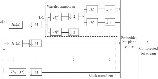
Although the wavelet tree provides an elegant hierarchi-cal data structure which facilitates quantization and entropy coding of the coefficients, the efficiency of the coder heav-ily depends on the transform’s ability in generating “enough” zero trees. For nonsmooth images (such as SAR image) that contain a lot of texture and edges, wavelet-based zero tree algorithms are not efficient. As will be seen shortly, our pro-posed OBTWC shown inFigure 1is a lot better in terms of achieving higher compression ratio while retaining the same perceptual image quality.
2.2. Theory of OBTWC
The theory of lattice structures and design methods for the two-channel filter banks are well established [13,17]. It is shown in [13] that linear-phase and paraunitary proper-ties cannot be simultaneously imposed on two-channel fil-ter banks, unless for the special case of Haar wavelets. How-ever, when more channels are allowed in the systems, both of the above properties can coexist [13]. For instance, the DCT (discrete cosine transform) and LOT (lapped orthogo-nal transform) are two examples where both the aorthogo-nalysis and synthesis filtersHk(z) andFk(z) are linear-phase FIR filters
x[n]
. . .
H0(z)
H1(z)
HM−1(z) . . . DC M M M . . . Wavelet transform
Hw1 0
H1w1 2
2
. . .
Hw1 0
Hw1 1 2 2 . . . Block transform Embedded bit-plane coder Compressed bit stream
Figure1: Proposed OBTWC.
paraunitary filter bank (OBTWC) is discussed. It is assumed that the number of channelsMis even and the filter lengthL is a multiple ofM, that is,L=NM.
It is shown in [6] thatM/2 filters (in analysis or synthesis) have symmetric impulse responses and the otherM/2 filters have antisymmetric impulse responses. Under the assump-tions on N,M, and on the filter symmetry, the polyphase transfer matrix Hp(z) of a linear-phase paraunitary filter
bank of degree N−1 can be decomposed as a product of orthogonal factors and delays [6], that is,
Hp(z)=SQTN−1Λ(z)TN−2Λ· · ·Λ(z)T0Q, (1)
where Q= I 0 0 J
, Λ(z)=
I 0
0 z−1I
,
S=√1
2
S0 0
0 S1 I J
I −J
.
(2)
HereI andJare the identity and reversed matrices, respec-tively.S0andS1can be anyM/2×M/2 orthogonal matrices
andTiareM×Morthogonal matrices
Ti=
I I
I −I
Ui 0
0 Vi
I I
I −I
=WΦiW, (3)
where Ui and Vi are arbitrary orthogonal matrices. The
factorization [17] covers all linear-phase paraunitary filter banks with an even number of channels. In other words, given any collection of filtersHk(z) that comprise such a filter
bank, one can obtain the corresponding matricesS,Q, and Tk(z). The synthesis procedure is given in [6]. The building
blocks in [17] can be rearranged into a modular form where both the DCT and LOT are special cases [6],
Hp(z)=KN−1(z)KN−2(z)· · ·K1(z)K0,
where Ki(z)=ΦiWΛ(z)W.
(4)
The class of OBTWCs, defined in this way, allows us to view the DCT and LOT as special cases, respectively, forN=1 and
N=2. The degrees of freedom reside in the matricesUiand
Vi which are only restricted to be realM/2×M/2
orthog-onal matrices. Similar to the lattice factorization in (1), the factorization in (4) is a general factorization that covers all linear-phase paraunitary filter banks withMeven and length
L=MN.
Based on our analysis, there still exists correlation be-tween DC coefficients. To decorrelate the DC band even more, several levels of wavelet decomposition can be used depending on the input image size. Besides the obvious in-crease in the coding efficiency of DC coefficients thanks to deeper coefficient trees, wavelets provide variably longer bases for the signal’s DC component, leading to smoother reconstructed images, that is, blocking artifacts are further reduced. Regularity objective can be added in the transform design process to produceM-band wavelets, and a wavelet-like iteration can be carried out using uniform-band trans-forms as well.
The complete proposed coder diagram is depicted in
Figure 1. It is a hybrid combination of block transform and wavelet transform. The waveform transform is used for the DC band and overlapped block transforms are used for other bands. The advantage is the enhanced capability of capturing and separating the localized signal components in the fre-quency domain.
2.3. Determination of block transform coefficients
The filter coefficients inHi(z) ofFigure 1require very careful
design. We use the following well-known guidelines for filter coefficients to produce a good perceptual image codec.
(i) The filter coefficients should be smooth and symmetric (or antisymmetric). Smoothness controls the noise in a region with constant background. Symmetry allows the use of symmetric extension to process the image’s borders.
blocks when the image is compressed. This blocking artifact is typical in JPEC because the DCT coefficients are not smooth at the ends.
(iii)The bandpass and highpass filters should have no DC leakage. Higher-frequency bands will be quantized severely. It is desirable for the lowpass band to contain all of the DC information. Otherwise, if the bandpass and highpass responses toω=0 are not zero, we see the checkerboard artifact.
(iv)The coefficients should be chosen to maximize coding gain. The coding gain is an approximate measure of energy compaction. A higher gain means higher en-ergy compaction.
(v)Their lengths should be reasonably short to avoid exces-sive ringing and reasonably long to avoid blocking. (vi) In the frequency range |ω| ≤ π/M,the bandpass and
highpass responses should be small. This minimizes the quantization effect on bandpass and highpass filters.
To satisfy the above properties, we used an optimization tech-nique. The cost function is a weighted linear combination of coding gain, DC leakage, attenuation around mirror fre-quencies, and stopband attenuation. It is defined as
Coverall=k1Ccoding gain+k2CDC+k3Cmirror
+k4Canalysis stopband+k5Csynthesis stopband
(5)
withkithe weighting factors.
The coding gain cost function is defined as
Ccoding gain=10 log σ 2
x M−1
k=0 σxi2fi2
1/M, (6)
whereσ2
xis the variance of the input signal,σxi2is the variance
of theith subband, andfi2is the norm of theith synthesis
filter.
The DC leakage cost function measures the amount of DC energy that leaks out to the bandpass and highpass sub-bands. The main idea is to concentrate all signal energy at DC into the DC coefficients. This proves to be advantageous in both signal decorrelation and in the prevention of discon-tinuities in the reconstructed signals. Low DC leakage can prevent the annoying checkerboard artifact that usually oc-curs when high-frequency bands are severely quantized. The DC cost function is defined as
CDC=
M−1
i=1
L−1
n=0
hi(n). (7)
The mirror frequency cost function is a generalization of CDC. Frequency attenuation at mirror frequencies is
impor-tant in the further reduction of blocking artifacts. The corre-sponding cost function is
Cmirror=
M−1
i=0 Hi
ejωm2, ω
m=
2πm
M , 1≤m≤
M 2.
(8)
Stopband attenuation criterion measures the sum of all of the filters’ energy outside the designated passbands. Mathemati-cally,
Canalysis stopband=
M−1
i=0 ω∈Ωstopband
Wia
ejωHi
ejω2dω,
Csynthesis stopband=
M−1
i=0 ω∈Ωstopband
Ws
i
ejωF
i
ejω2dω.
(9)
In the analysis bank, the stopband attenuation cost helps in improving the signal decorrelation and decreasing the amount of aliasing. In meaningful images, we know a pri-ori that most of the energy is concentrated in low-frequency region. Hence, high stopband attenuation in this part of the frequency spectrum becomes extremely desirable. In the syn-thesis bank, the reverse is true. Synsyn-thesis filters covering low-frequency bands need to have high stopband attenuation near and/or atω=πto enhance their smoothness. The bi-ased weighting can be enforced using two simple linear func-tionsWia(ejω) andWis(ejω).
The optimization of cost function in (5) is performed by using a nonlinear optimization routine calledSimplexin MATLAB. The results are the optimized filter coefficients.
2.4. Comparison summary between OBTWC, DCT, and wavelet
Consumers and manufacturers are pushing for higher and higher number of pixels in digital cameras, camcorders, and high-definition TVs. All these advancements call for strin-gent demands for faster and nicer compression codecs. It will be ideal for a codec to have fast compression and, at the same time, achieves very satisfactory perceptual quality and signal-to-noise ratio. The proposed OBTWC has exactly these qual-ities.
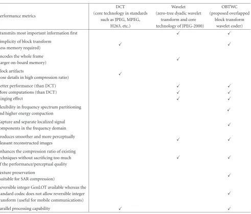
Table 1 summarizes the comparison between three co-decs. It can be seen that the proposed codec has more ad-vantages than DCT and wavelet. It is the balanced quality between computational speed and performance that makes the proposed OBTWC stands out among the other codecs.
2.5. Implementation of a complete coder
The proposed method was implemented by replacing the transform of an H.263+ codec by the GenLOT transform (using only the I-frame mode for still image compression), with appropriate coefficient reordering. The entropy coding and other parts of the codec are kept the same.
3. STILL IMAGE COMPRESSION
Table1: Comparison of different codecs.
Performance metrics
DCT Wavelet OBTWC
(core technology in standards (zero-tree dyadic wavelet (proposed overlapped such as JPEG, MPEG, transform and core block transform
H263, etc.) technology of JPEG-2000) wavelet coder)
Transmits most important information first
Simplicity of block transform
(less memory required)
Encodes the whole frame
(larger on-board memory)
Block artifacts
(lose details in high compression ratio)
Better performance (than DCT)
More computations (than DCT)
Ringing effect
Flexibility in frequency spectrum partitioning
and higher energy compaction
Capture and separate localized signal
components in the frequency domain
Produces smoother and more perceptually
pleasant reconstructed images
Enhances the compression ratio of existing
techniques without sacrificing too much of the performance/perceptual quality
Texture preservation
(suitable for SAR compression)
Reversible integer GenLOT available whereas the
standard codec does not allow reversible integer transform (useful for mobile communications)
Parallel processing capability
In terms of military applications, one can directly apply our still image compression algorithm for image storage and archiving.
3.1. Benchmark images compression
In this section, we summarize the application of several progression transmission codecs, including SPIHT (wavelet-based method), JPEG, JPEG-2000, and our OBTWC. Bench-mark images (Lena and Barbara) were used in this compara-tive study.
The objective performance criterion we used is called peak signal-to-noise ratio (PSNR) which is defined as
PSNR=10 log 255
2
(1/M)Mn=1on−rn
2, (10)
whereonis thenth pixel in the original image andrnis the
nth pixel in the reconstructed image. This is a popular ob-jective method to measure distortion in image compression
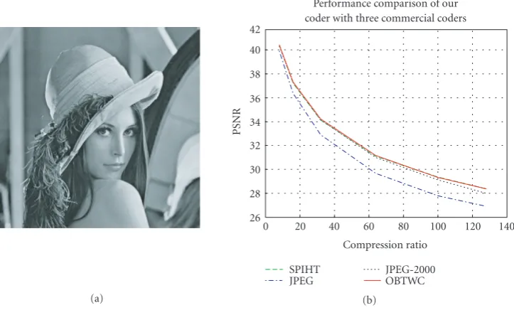
Table2: Coding results of various progressive coders for Lena.
Lena Progressive transmission coders Comp. ratio SPIHT (9-7WL) JPEG JPEG-2000 OBTWC
1 : 8 40.41 39.91 40.32 40.43
1 : 16 37.21 36.38 37.27 37.32
1 : 32 34.11 32.90 34.14 34.23
1 : 64 31.10 29.67 31.00 31.16
1 : 100 29.35 27.80 29.12 29.31
1 : 128 28.38 26.91 28.00 28.35
applications. The higher the PSNR is, the better the compres-sion and decomprescompres-sion performance is.
(a)
26 28 30 32 34 36 38 40 42
PSNR
0 20 40 60 80 100 120 140
Compression ratio SPIHT
JPEG
JPEG-2000 OBTWC Performance comparison of our coder with three commercial coders
(b)
Figure2: PSNRs of various codecs at different compression ratios for Lena.
Table3: Coding results of various progressive coders for Barbara.
Barbara Progressive transmission coders Comp. ratio SPIHT (9-7WL) JPEG JPEG 2000 OBTWC
1 : 8 36.41 36.31 37.17 38.08
1 : 16 31.40 31.11 32.29 33.47
1 : 32 27.58 27.28 28.39 29.53
1 : 64 24.86 24.58 25.42 26.37
1 : 100 23.76 23.42 24.06 24.95
1 : 128 23.35 22.68 23.37 24.01
Similarly,Table 3andFigure 3summarize the PSNRs for Barbara. Again, our proposed codec performed consistently better than all other codecs.
3.2. SAR image compression
We have compressed four types of SAR images: two types from the Air Force, one type from the Army, and one type from NASA. Our algorithm outperforms both wavelet and JPEG coders. The wavelet coder was developed by Summus, Inc. We purchased one copy. It was claimed by Summus that its coder is better than JPEG and other wavelet-based coders. The baseline JPEG coder is a shareware from the Internet. The web address ishttp://www.geocities.com/SiliconValley/ 7726/.
3.2.1. Air Force cluttered SAR image
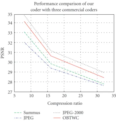
The SAR image (size: 512×480, gray scale: 8 bits/pixel) was supplied by Air Force Wright Patterson Laboratory (Marvin Soraya). We applied four algorithms to it: our OBTWC algo-rithm, Summus wavelet coder, JPEG-2000, and JPEG. Three
compression ratios were tried. The perceptual differences be-tween the various coders are hard to discern by human eyes. However, the objective performance index (PSNR) tells a big difference. The PSNR is summarized inTable 4. We also plot-ted PSNRs versus compression ratios. As shown inFigure 4, although our coder has comparable performance as the com-mercial products, in terms of computational complexity, our algorithm allows parallel processing and hence is much more efficient than other codecs.
3.2.2. Army’s SAR image
The SAR image (size: 764×764, gray scale: 8 bits/pixel) was supplied by Army Research Laboratory in Fort Monmouth. Again, four algorithms were applied and the performance is summarized inTable 5. The PSNRs were also plotted against the compression ratios (Figure 5). FromTable 5, one can see that our codec is slightly inferior to JPEG-2000 but much better than the other two. But from practical implementation perspective, our codec is much simpler and hence will offer significant advantage for large images such as high-definition TV images.
3.2.3. NASA’s SAR image
(a)
22 24 26 28 30 32 34 36 38 40
PSNR
0 20 40 60 80 100 120 140
Compression ratio SPIHT
JPEG
JPEG-2000 OBTWC Performance comparison of our coder with three commercial coders
(b)
Figure3: PSNRs of various codecs at different compression ratios for Barbra.
27 28 29 30 31 32 33 34 35
PSNR
5 10 15 20 25 30 35
Compression ratio Summus
JPEG
JPEG-2000 OBTWC Performance comparison of our coder with three commercial coders
Figure4: PSNR of four compression methods.
The image (size: 945×833, color depth: 8 bits/pixel) shown in Figure 6 was a recently released image from the SIR-C/X-SAR Project. We applied OBTWC, Summus, JPEG-2000, and JPEG codecs to it. The results are summarized in
Table 6. The PSNRs versus compression ratios are plotted be-sidesTable 6. Except the 32 : 1 compression ratio case, our OBTWC outperforms the other codecs in the other two cat-egories. Even in the 32 : 1 case, the OBTWC is only 0.01 dB less than the wavelet coder is. The plots inFigure 7show the PSNRs of the three codecs. The OBTWC and Summus have similar performance in this case.
Table4: Performance comparison of our codec with 3 commercial codecs for the Air Force SAR image.
Algorithm\
compression ratio OBTWC Summus JPEG JPEG-2000
8 34.14 33.06 32.02 34.77
16 30.64 29.83 29.40 31.16
32 28.42 27.78 27.61 28.95
Table5: Performance comparison of our codec with three com-mercial codecs for an Army SAR image.
Algorithm\
compression ratio OBTWC Summus JPEG JPEG-2000
8 38.07 36.73 36.32 39.41
16 35.05 33.90 33.57 36.02
32 32.52 31.84 31.21 33.02
3.3. Color image compression
31 32 33 34 35 36 37 38 39 40
PSNR
5 10 15 20 25 30 35
Compression ratio Summus
JPEG
JPEG-2000 OBTWC Performance comparison of our coder with three commercial coders
Figure5: PSNRs of four codecs.
Figure6: Raw image from NASA.
3.4. Image enhancement of reconstructed images
The ringing effects in reconstructed images with high com-pression ratios are caused by the long filter lengths in OBTWC. Although the ringing effect here is less significant than wavelet coders are, it is still an annoying artifact that af-fects the visual perception of a reconstructed image. Here we propose two approaches to minimize the ringing artifacts. It is worth to mention that image enhancement is performed at the receiving end, and hence this post-processing will not affect the transmission speed.
3.4.1. Post-processing using nonlinear morphological filters
The key idea underlying the deringing algorithm is to avoid filtering the entire image blindly, but instead to identify the regions contaminated by ringing and apply the nonlinear smoothing filter only to these regions. As such, the algorithm is a signal-dependent (spatially varying) technique which re-quires the extraction of certain parameters from the input
Table6: Compression performance of 4 codecs to NASA SAR im-age.
Algorithm\
compression ratio OBTWC Summus JPEG JPEG-2000
8 27.44 27.25 26.07 27.87
16 24.58 24.51 23.22 24.44
32 22.40 22.41 21.71 22.17
21 22 23 24 25 26 27 28
PSNR
5 10 15 20 25 30 35
Compression ratio Summus
JPEG
JPEG-2000 OBTWC Performance comparison of our coder with three commercial coders
Figure7: PSNRs of four codecs.
image. The choice of a morphological smoothing operator was due to its fit to the purpose and also its very low compu-tational complexity.
Edge detection
Since the ringing artifact is known to be associated with step edges, the algorithm starts with an edge detection process on the input image. In case of compressed images, the edge de-tection process is even further complicated because of the blur (associated with compression) which typically causes false negatives (undetected edges) and also the ringing arti-fact ripples which typically cause false positives (false edges). Consequently, we designed a 3-phase edge detection algo-rithm in which the following hold.
(1) The first phase is a baseline edge detection algorithm employing Sobel edge detection operator (5×5). The associated threshold for this baseline algorithm is ex-tracted from the input image by paying attention to the ringing around the step edges so that to the binary edge map, only a very little amount of noise due to ringing ripples penetrates.
Table7: Summary of comparative studies for color images.
Images\
PSNR
JPEG 32 : 1
Summus JPEG-2000
OBTWC 32 : 1
JPEG
Summus 64 : 1
JPEG-2000
OBTWC JPEG 100 : 1
Summus 100 : 1
JPEG-2000
OBTWC 100 : 1
32 : 1 64 : 1 64 : 1
32 : 1 64 : 1 100 : 1
2s1 31.56 32.44 31.96 32.18 28.78 29.67 28.77 29.52 26.64 28.18 27.15 28.20
T62 28.45 29.07 28.70 30.05 25.37 26.37 25.72 27.15 23.45 24.97 24.24 25.61
Zil131 28.33 29.15 28.56 30.03 25.36 26.27 25.47 26.99 23.44 24.87 23.94 25.42
Btr60 30.48 29.07 31.75 32.63 27.93 26.37 28.70 29.79 26.22 24.97 26.87 28.32
26 27 28 29 30 31 32 33
PSNR
30 40 50 60 70 80 90 100
Compression ratio Summus
JPEG
JPEG-2000 OBTWC Performance comparison of our coder with three commercial coders
(a) 2s1
23 24 25 26 27 28 29 30 31
PSNR
30 40 50 60 70 80 90 100
Compression ratio Summus
JPEG
JPEG-2000 OBTWC Performance comparison of our coder with three commercial coders
(b) T62
23 24 25 26 27 28 29 30 31
PSNR
30 40 50 60 70 80 90 100
Compression ratio Summus
JPEG
JPEG-2000 OBTWC Performance comparison of our coder with three commercial coders
(c) Btr60
24 25 26 27 28 29 30 31 32 33
PSNR
30 40 50 60 70 80 90 100
Compression ratio Summus
JPEG
JPEG-2000 OBTWC Performance comparison of our coder with three commercial coders
(d) Zil131 Figure8: PSNRs of three codecs for the four color images.
in the binary edge map. To clean this noise, we use a morphological filter consisting of some pruning and hit-or-miss operations.
(3) The cleaned edge map typically has significant discon-tinuities along many of its edge traces. In this case
Edge mask
The second major step is the generation of the so-called “edge mask.” This phase is carried out essentially by a binary clos-ing operation (3×3) on the output of the edge detection phase. The edge mask serves the very important purpose of protecting many genuine image features and high-frequency details such as edges with narrow pulse-like profiles and tex-ture from being destroyed by the consequent morphological smoothing operation.
Filtering mask
The third major phase is the generation of the so-called “fil-tering mask.” This phase is carried out by a dilation opera-tion (3×3) on the output of the edge detection phase (to isotropically mark the regions surrounding the edges where we know that only these regions are subject to being con-taminated with ringing) and then an exclusive-OR operation between the dilation result and the edge mask (output of the second phase) which will remove the regions covered by the edge mask from the filtering mask so that the regions covered by the edge mask will not be filtered. This sequence of oper-ations generates the so-called raw filtering mask. One major feature of the algorithm is that it is employing human visual system (HVS) properties to further process the raw filtering mask and eliminate from it those regions which because of their content and also the masking properties of HVS will not reveal the ringing noise confined to their boundaries. For example, textured regions which could not be identified be-cause of blur in the edge detection step, and therefore not protected by the edge mask, will typically be detected during this phase and consequently removed from the raw filtering mask. The above-mentioned upper local variance limit at-tributable to ringing ripples is a signal-dependent quantity as well as its dependence on the compression level and we han-dle it in the appropriate way and extract it from the image in a spatially adaptive way. Once the HVS-based modification is performed on the raw filtering mask, we have the so-called final filtering mask or shortly the filtering mask.
Morphological smoothing
The fourth major phase of the algorithm is the morpho-logical smoothing of the image regions lying under the ex-posed regions of the filtering mask. For this purpose, we use a simple averaged gray-level morphological opening and clos-ing filter (3×3). The opening filter in a sense extracts the lower bounding envelope of the ringing ripples, and in a dual manner the closing filter in a sense extracts the upper bound-ing envelope of the rbound-ingbound-ing ripples, and in their arithmetical average the ringing ripples are to a very great extent elimi-nated. All of these processings are performed through integer arithmetic and local min/max operations on gray-level data. Needless to say, the binary morphological operations of the previous steps are performed by logical shift, and AND/OR operations on binary data.
Final image generation
The final phase is the generation of the filter deringing out-put. For this purpose, we do the following. We keep the re-gions of the input image covered by the filtering mask in-tact. However, the regions of the input image exposed by the filtering mask (i.e., those regions which are filtered in the fourth phase) are copied from the output of the morpholog-ical smoothing filter and pasted on to the input image. This generates the output of the deringing filter.
We applied the deringing filter to Lena.Figure 9shows the results for a compression ratio 100 : 1. It can be seen that the image after post-processing is much better in terms of perceptual performance than the reconstructed image in the middle.
3.4.2. Post-processing using median filter
This approach consists of two steps. First, an edge detec-tion algorithm (Canny’s algorithm) is used to determine the significant edges in a reconstructed image. Second, a median filter (3×3) is then applied to eliminate the ringing. A me-dian filter is a nonlinear filter that chooses the meme-dian of 9 elements in a 3×3 window. The idea is to eliminate high-amplitude noise without blurring the edges.Figure 10shows the results. The perceptual performance did improve after post-processing. The perceptual performance improvement of median filtering is comparable to morphological filter de-scribed inSection 3.4.1 It appears that the median filter is simpler than the previous approach.
3.5. New region-of-interest (ROI) enhancement capability
In progressive image transmission, the most important in-formation is transmitted first. The importance of pixels in a picture is reflected by the magnitude of its transformed co-efficients. Therefore, the key idea here is that if we want to highlight a region in an image, we need to scale up the co-efficients in that particular region. We achieve this goal by using Visual Basic. An interface of the software is shown in
Figure 11. First, an image is loaded onto the screen. Second, a mouse is used to draw a box that one wants to highlight. The coordinates of the box are passed to the image algorithm so that the appropriate blocks will be highlighted. Third, a weight factor is selected from the screen. The weighting fac-tor scales all the coefficients in the region of interest.
Figure 12shows the performance of image compression with ROI enhancement. The tip of the gun barrel of a tank is highlighted. It can be seen that the image with ROI enhance-ment is better than the one without this option.
3.6. Computational complexity analysis
(a) 100 : 1 by OBTWC (b) 100 : 1 after post-processing Figure9: Effects of morphological deringing filter on Lena.
(a) 100 : 1 (b) 100 : 1 after post-processing Figure10: Post-processing using median filter.
schemes.Table 8 summarizes the number of computations by using software for a givenN×Nimage. It is worth men-tioning that if no parallel implementation for both DCT and GenLOT is done, then it can be seen that DCT is the most efficient one, followed by wavelet and GenLOT. Figure 13
shows the number of computations versus image sizeN. All three grow exponentially if no parallel implementation is used.
However, if one implements the DCT and GenLOT in a parallel manner by taking advantage of the block trans-formation characteristics, one can see that the DCT and GenLOT can be very efficient. As can be seen fromTable 9
andFigure 14, DCT and GenLOT algorithms stay almost flat while the wavelet transform still grows exponentially.
3.7. Summary of the results
From all the experiments presented above, it is found that the proposed method can compress images with better or about the same PSNR as the two competing approaches. In
all these examples, the visual quality of the compressed image from the proposed method is often better than the competing approaches. For those cases where the proposed method has slightly lower PSNR than the wavelet coder, there is little dif-ference in visual quality. Also, the proposed post-processing techniques are found to be effective in removing the ringing artifacts at extreme compression ratio. In particular, the sys-tem supports selective enhancement of an ROI.
4. CONCLUSIONS AND FURTHER RESEARCH
Figure11: Interface of the region-of-interest program.
ROI that needs to be emphasized
(a) Original image
(b) 100 : 1 compression with enhanced tip of gun barrel
(c) 100 : 1 compression without ROI enhancement
Figure12: Comparison of images with and without ROI enhancement.
control the compression ratio at certain critical regions of the images so that target recognition performance can be preserved. Extensive comparative studies with a commercial product (Summus—a wavelet-based codec), a JPEG base-line codec, and a JPEG-2000 codec showed that the proposed method achieved better performance in most cases.
While there exists extensive work on the reduction of blocking artifacts in a DCT-based scheme, such as the projection-onto-convex-sets (POCSs) approaches and others [5,18–25], they are mostly post-processing techniques that work on a blocky image. Theoretically, since the information is already lost, these post-processing techniques cannot really reconstruct the original image but only improve the visual
Table8: Software implementation: computational complexity of DCT, GenLOT, and wavelet for a givenN×Nimage.
Method\complexity Multiplications Additions
8∗8 DCT 3.25N2 7.25N2
8∗40 GenLOT 40N2 78N2
9/7 4-L wavelet 11.9N2 18.6N2
0 0.5 1 1.5 2 2.5 3 3.5 4 4.5
×107
N
u
mber
of
m
ultiplications
100 200 300 400 500 600 700 800 900 1000 1100
N
8×8 DCT 8×40 GenLOT 9/7 4−Lwavelet
Multiplications
(a)
0 1 2 3 4 5 6 7 8 9
×107
N
u
mber
of
additions
100 200 300 400 500 600 700 800 900 1000 1100
N
8×8 DCT 8×40 GenLOT 9/7 4−Lwavelet
Additions
(b)
Figure13: Software implementation. (All three grow exponentially with wavelet the least efficient.)
0 2 4 6 8 10 12 14
×104
N
u
mber
of
m
ultiplications
100 200 300 400 500 600 700 800 900 1000 1100
N
8×8 DCT 8×40 GenLOT 9/7 4−Lwavelet×100
Multiplications
(a)
0 2 4 6 8 10 12 14
×104
N
u
mber
of
additions
100 200 300 400 500 600 700 800 900 1000 1100
N
8×8 DCT 8×40 GenLOT 9/7 4−Lwavelet×100
Additions
(b)
Figure14: Parallel hardware implementation. (DCT and GenLOT stay almost flat; wavelet grows exponentially.)
issue. Nevertheless, it would be an interesting future task to compare such an overlapped transform approach with one leading deblocking algorithm to examine the performance of both approaches.
ACKNOWLEDGMENTS
This research was supported by the Ballistic Missile Defense Organization (BMDO) under Contract no. F33615-99-C-1474 and managed by the Air Force. The encouragement
Table9: Parallel hardware implementation: computational com-plexity of DCT, GenLOT, and wavelet.
Method\complexity Multiplications Additions
8∗8 DCT 3.25×64 7.25×64
8∗40 GenLOT 40×64 78×64
9/7 4-L wavelet 11.9N2 18.6N2
REFERENCES
[1] C. Kwan, B. Li, R. Xu, et al., “SAR image compression using wavelets,” inWavelet Applications VIII, vol. 4391 ofProceedings of SPIE, pp. 349–357, 2001.
[2] W. B. Pennebaker and J. L. Mitchell,JPEG: Still Image Com-pression Standard, Van Nostrand Reinhold, New York, NY, USA, 1993.
[3] H. S. Malvar,Signal Processing with Lapped Transforms, Artech House, Norwood, Mass, USA, 1992.
[4] H. S. Malvar, “Biorthogonal and nonuniform lapped trans-forms for transform coding with reduced blocking and ring-ing artifacts,”IEEE Transactions on Signal Processing, vol. 46, pp. 1043–1053, 1998.
[5] H. C. Reeves and J. S. Lim, “Reduction of blocking effects in image coding,”Optical Engineering, vol. 23, no. 1, pp. 34–37, 1984.
[6] R. L. de Queiroz, T. Nguyen, and K. R. Rao, “GenLOT: gener-alized linear-phase lapped orthogonal transform,”IEEE Trans-actions on Signal Processing, vol. 44, no. 3, pp. 497–507, 1996. [7] T. Tran and T. Nguyen, “OnM-channel linear phase FIR filter
banks and application in image compression,”IEEE Transac-tions on Signal Processing, vol. 45, no. 9, pp. 2175–2187, 1997. [8] Z. Xiong, K. Ramchandran, and M. T. Orchard,
“Space-frequency quantization for wavelet image coding,”IEEE Trans-actions on Image Processing, vol. 6, no. 5, pp. 677–693, 1997. [9] J. P. Princen, A. W. Johnson, and A. B. Bradley,
“Sub-band/transform coding using filter bank designs based on time domain aliasing cancellation,” inProceedings of the IEEE Inter-national Conference on Acoustics, Speech and Signal Processing (ICASSP ’87), pp. 2161–2164, Dallas, Tex, USA, April 1987. [10] J. M. Shapiro, “Embedded image coding using zerotrees of
wavelet coefficients,”IEEE Transactions on Signal Processing, vol. 41, no. 12, pp. 3445–3462, 1993.
[11] A. Said and W. A. Pearlman, “A new fast and efficient image codec on set partitioning in hierarchical trees,”IEEE Transac-tions on Circuits and Systems for Video Technology, vol. 6, pp. 243–250, 1996.
[12] “Compression with reversible embedded wavelets,” RICOH Company Ltd. submission to ISO/IEC JTC1/SC29/WG1 for the JTC1.29.12 work item, 1995. Can be obtained on the World Wide Web,http://www.crc.ricoh.com/CREW. [13] P. P. Vaidyanathan, Multirate Systems and Filter Banks,
Prentice-Hall, Englewood Cliffs, NJ, USA, 1993.
[14] G. Strang and T. Nguyen,Wavelets and Filter Banks, Wellesley-Cambridge Press, Wellesley, Mass, USA, 1996.
[15] M. Vetterli and J. Kovaˇcevi´c,Wavelets and Subband Coding, Prentice-Hall, Englewood Cliffs, NJ, USA, 1995.
[16] R. A. DeVore, B. Jawerth, and B. J. Lucier, “Image compres-sion through wavelet transform coding,”IEEE Transactions on Information Theory, vol. 38, no. 2, part II, pp. 719–746, 1992. [17] I. Daubechies,Ten Lectures on Wavelets, CBMS Conference
Se-ries, SIAM, Philadelphia, Pa, USA, 1992.
[18] N. F. Law and W. C. Siu, “Successive structural analysis using wavelet transform for blocking artifacts suppression,”Signal Processing, vol. 81, no. 7, pp. 1373–1387, 2001.
[19] A. Zakhor, “Iterative procedures for reduction of blocking ef-fects in transform image coding,”IEEE Transactions on Circuits and Systems for Video Technology, vol. 2, no. 1, pp. 91–95, 1992. [20] Y. Yang, N. P. Galatsanos, and A. K. Katsaggelos, “Regular-ized reconstruction to reduce blocking artifacts of block dis-crete cosine transform compressed images,”IEEE Transactions on Circuits and Systems for Video Technology, vol. 3, no. 6, pp. 421–432, 1993.
[21] Y. Yang and N. P. Galatsanos, “Projection-based spatially adap-tive reconstruction of block-transform compressed images,” IEEE Transactions on Image Processing, vol. 4, no. 7, pp. 896– 908, 1995.
[22] S. D. Kim, J. Yi, H. M. Kim, and J. B. Ra, “A deblocking filter with two separate mode in block-based video coding,” IEEE Transactions on Circuits and Systems for Video Technol-ogy, vol. 9, no. 2, pp. 156–160, 1999.
[23] H. W. Park and Y. L. Lee, “A post-processing method for re-ducing quantization effects in low bit-rate moving picture coding,”IEEE Transactions on Circuits and Systems for Video Technology, vol. 9, no. 2, pp. 161–171, 1999.
[24] A. W.-C. Liew and H. Yan, “Blocking artifacts suppression in blockcoded images using overcomplete wavelet representa-tion,”IEEE Transactions on Circuits and Systems for Video Tech-nology, vol. 14, no. 4, pp. 450–461, 2004.
[25] C. Weerasinghe, A. W.-C. Liew, and H. Yan, “Artifact reduc-tion in compressed images based on region homogeneity con-straints using the projections onto convex sets algorithm,” IEEE Transactions on Circuits and Systems for Video Technol-ogy, vol. 12, no. 10, pp. 891–897, 2002.
C. Kwan received his B.S. degree in elec-tronics with honors from the Chinese Uni-versity of Hong Kong in 1988 and his M.S. and Ph.D. degrees in electrical engineer-ing from the University of Texas at Arlengineer-ing- Arling-ton in 1989 and 1993, respectively. From April 1991 to February 1994, he worked in the Beam Instrumentation Department of the Superconducting Super Collider Labo-ratory (SSC) in Dallas, Tex, where he was
heavily involved in the modeling, simulation, and design of mod-ern digital controllers and signal processing algorithms for the beam control and synchronization system. He received an Inven-tion Award for his work at SSC. Between March 1994 and June 1995, he joined the Automation and Robotics Research Institute in Fort Worth, where he applied neural networks and fuzzy logic to the control of power systems, robots, and motors. Since July 1995, he has been with Intelligent Automation, Inc. in Rockville, Md. He has served as the Principal Investigator/Program Manager for more than 65 different projects, with total funding exceeding 20 million dollars. Currently, he is the Vice President, leading research and de-velopment efforts in signal/image processing and controls. He has published more than 40 papers in archival journals and has had 100 additional refereed conference papers.
B. Lireceived a Ph.D. degree in electrical en-gineering from the University of Maryland, College Park, in 2000. He is currently an As-sistant Professor of computer science and engineering in the Arizona State University. He was previously a Senior Researcher with Sharp Laboratories of America (SLA), Ca-mas, Wash, working on multimedia analy-sis for consumer applications. He was the Technical Lead in developing Sharp’s
R. Xureceived the B.S. degree from Jiangsu University in 1982, and the M.S. degree in 1988 from Xi’an Jiaotong University, China, both in electrical engineering. From 1982 to 1985 and from 1988 to 1993, he was teaching at Jiangsu University as an Assistant Professor. From 1993 to 1994, he was a Visiting Scholar at Lehrstuhl f¨ur All-gemeine und Theoretische Elektrotechnik, Universit¨at Erlangen-N¨urnberg, Germany. Since 1994, he has been with Intelligent Au-tomation, Inc. (IAI), USA, where he is currently a Principal Engi-neer. His research interests include array signal processing, image processing, fault diagnostics, network security, and control theory and applications. Over the last 11 years with IAI, he has worked on many different research projects in the above areas funded by various US government agencies such as DoD and NASA. He has also published over 20 journal and conference papers in the related areas.
X. Lireceived his B.S. and M.S. degrees in electrical engineering from Xi’an Jiaotong University, China, in 1992 and 1995, re-spectively. He obtained his Ph.D. degree in electrical engineering from the University of Cincinnati, Ohio, in 2004. From 1995 to 1999, he was an Assistant Professor at Xi’an Jiaotong University. He worked as a Visit-ing Researcher at Siemens Corporate Re-search (SCR), Princeton, NJ, in 2002, and
Mitsubishi Electronic Research Labs (MERL), Cambridge, Mass, in 2003. Since 2004, he has been with Intelligent Automation, Inc. as a Research Engineer. His research interests include image/video pro-cessing and analysis, optical/electronic imaging, medical imaging, computer vision, machine learning, pattern recognition, artificial intelligence, real-time system, and data visualization. He is a Mem-ber of the IEEE, SPIE, and Sigma Xi.
T. Tranreceived the B.S. and M.S. degrees from the Massachusetts Institute of Tech-nology, Cambridge, in 1993 and 1994, re-spectively, and the Ph.D. degree from the University of Wisconsin, Madison, in 1998, all in electrical engineering. In July of 1998, he joined the Department of Electrical and Computer Engineering, The Johns Hopkins University, Baltimore, Md, where he cur-rently holds the rank of Associate Professor.
His research interests are in the field of digital signal processing, particularly in multirate systems, filter banks, transforms, wavelets, and their applications in signal analysis, compression, processing, and communications. He was the Codirector (with Professor J. L. Prince) of the 33rd Annual Conference on Information Sciences and Systems (CISS’99), Baltimore, Md, in March 1999. He received the NSF CAREER Award in 2001. In the summer of 2002, he was an ASEE/ONR Summer Faculty Research Fellow at the Naval Air War-fare Center Weapons Division (NAWCWD) at China Lake, Calif. He currently serves as an Associate Editor of the IEEE Transactions on Signal Processing as well as IEEE Transactions on Image Pro-cessing. He is also a Member of the Signal Processing Theory and Methods (SPTM) Technical Committee of the IEEE Signal Process-ing Society.
T. Nguyen received the B.S, M.S, and Ph.D. degrees in electrical engineering from the California Institute of Technology, Pasadena, in 1985, 1986, and 1989, respec-tively. He was with MIT Lincoln Labora-tory from June 1989 to July 1994, as a mem-ber of the technical staff. During the aca-demic year 1993–1994, he was a Visiting Lecturer at MIT and an Adjunct Professor at Northeastern University. From August 1994