Imperfection Insensitive Thin Shells
Thesis by
Xin Ning
In Partial Fulfillment of the Requirements for the Degree of
Doctor of Philosophy
California Institute of Technology Pasadena, California
2015
Acknowledgements
Studies of imperfection-sensitivity of thin-shell structures were pioneered by many researchers in GALCIT, including Theodore von K´arm´an and Hsue-Shen Tsien, who went back to China in the 1950s and became the father of the Chinese space program. The work presented in this thesis was built upon the shoulders of these giants. It has been a great honor for me to pursue a PhD in Aeronautics at Caltech.
First and foremost, I would like to express my deepest gratitude to my advisor, Professor Sergio Pellegrino, who gave me the opportunity to study in GALCIT and led me into the fascinating world of thin-shell structures. The work presented in this thesis would not have been possible without his vision, guidance, support, and encouragement. I am especially impressed by his sharp mind for simplifying a complex problem and solving it in an intuitive, elegant, and very effective way. I am particularly grateful for the huge efforts he spent on teaching us how to make excellent presentations. I have learned so much from him in the past six years, and I am sure I will forever benefit from his guidance during my PhD studies.
I am grateful for the valuable comments and suggestions from the members of my thesis committee: Professors Jim Beck, Dennis Kochmann, and Guruswami Ravichandran. I also thank Professors Ekkehard Ramm, Martin M. Mikulas, John Hutchinson, Jean-Fran¸cois Jullien, Petros Koumoutsakos, Chris Calladine, Paolo Ermanni, Kwang-Chun Park, Tony Waas, Paul Weaver, Katia Bertoldi, and Ryan Elliot for help and advice during the course of this study. In addition, I would like to extend my gratitude to Ted Nye and Tim Shinbara for inspiring my first research project. I thank Professor Jos´e Andrade and Ryan Hurley for their help with the high-speed camera.
I would like to thank my current and former colleagues at the Space Structures Laboratory for their con-structive and helpful suggestions, comments, and discussions. My gratitude goes to Manan Arya, Melanie Delapierre, Kristina Hogstrom, Maria Sakovsky, John Steeves, Yuchen Wei, Lee Wilson, Dr. Stephen Bon-giorno, Dr. Federico Bosi, Dr. Kathryn Jackson, Dr. Nicolas Lee, Dr. Ignacio Maqueda Jim´enez, Dr. Keith Patterson, and Markus Schatz. I also need to particularly thank Dr. Xiaowei Deng, Dr. Francisco L´opez Jim´enez, Dr. Kawai Kwok, and Dr. Chinthaka Mallikarachchi for their help and mentorship during my first few years at Caltech.
I would like to express my appreciation to the Resnick Sustainability Institute at Caltech for providing me with a graduate fellowship. The financial support for my first research project from the Northrop Grumman Aerospace Systems is also gratefully acknowledged.
I am grateful to all my friends and classmates at Caltech who have made my life much easier. They are always there to help me with any difficulties and we have shared many memorable moments together.
Abstract
The buckling of axially compressed cylindrical shells and externally pressurized spherical shells is extremely sensitive to even very small geometric imperfections. In practice this issue is addressed by either using overly conservative knockdown factors, while keeping perfect axial or spherical symmetry, or adding closely and equally spaced stiffeners on shell surface. The influence of imperfection-sensitivity is mitigated, but the shells designed from these approaches are either too heavy or very expensive and are still sensitive to imperfections. Despite their drawbacks, these approaches have been used for more than half a century.
This thesis proposes a novel method to design imperfection-insensitive cylindrical shells subject to axial compression. Instead of following the classical paths, focused on axially symmetric or high-order rotationally symmetric cross-sections, the method in this thesis adopts optimal symmetry-breaking wavy cross-sections (wavy shells). The avoidance of imperfection sensitivity is achieved by searching with an evolutionary algorithm for smooth cross-sectional shapes that maximize the minimum among the buckling loads of ge-ometrically perfect and imperfect wavy shells. It is found that the shells designed through this approach can achieve higher critical stresses and knockdown factors than any previously known monocoque cylindri-cal shells. It is also found that these shells have superior mass efficiency to almost all previously reported stiffened shells.
Contents
Acknowledgements iii
Abstract v
1 Introduction 1
1.1 Overview . . . 1
1.1.1 Axially Compressed Cylindrical Shells . . . 2
1.1.2 Externally Pressurized Spherical Shells. . . 3
1.2 Objective and Scope . . . 4
1.3 Layout of Dissertation . . . 4
2 Background and Literature Review 6 2.1 Reviews of Axially Compressed Cylindrical Shells . . . 6
2.1.1 Theories and Design Methods . . . 6
2.1.1.1 Effects of Imperfections on Cylindrical Shells . . . 6
2.1.1.2 Design of Cylindrical Shells Against Buckling. . . 8
2.1.1.3 Manufacturing Imperfection Signature Method . . . 9
2.1.1.4 Alternative Approaches: Aster Shell, Pseudo-Cylindrical Shell, and Ramm’s Method . . . 10
2.1.1.5 Efficiency Chart . . . 12
2.1.2 Experimental Methods. . . 13
2.1.2.1 Manufacture of Cylindrical Shells for Research . . . 13
2.1.2.2 Methods of Measuring Imperfections. . . 14
2.1.2.3 Measurement of Shell Deformation and Recording of Buckling Behavior . . . 15
2.1.3 Computational Methods . . . 16
2.1.3.1 Overview on Methods for Buckling Analysis of Corrugated/Stiffened Cylin-drical Shells . . . 16
2.1.3.2 Stiffness Matrix Method. . . 18
2.1.3.4 Comparison between Stiffness Matrix Method and Bloch Wave Method . . . 23
2.2 Reviews of Externally Pressurized Spherical Shells . . . 24
2.2.1 Analytical and Numerical Studies. . . 24
2.2.2 Experimental Studies . . . 25
3 Design of Imperfection-Insensitive Cylindrical Shells 27 3.1 Methodology . . . 27
3.1.1 Parametrization of Cross-Section . . . 27
3.1.2 Formulation of Optimization Problem . . . 29
3.1.3 Numerical Implementation . . . 31
3.2 Wavy Shell Designs. . . 33
3.2.1 Dimensions and Material Properties . . . 33
3.2.2 Reference Cylindrical Shell . . . 35
3.2.3 Mirror-Symmetric Shells . . . 36
3.2.4 4-Fold Symmetric Shells . . . 37
3.3 Comparison and Analysis of Wavy Shell Designs . . . 39
3.3.1 Comparison . . . 39
3.3.2 Analysis of Shell Cross-Sections. . . 40
3.3.3 Effects of Imperfection Amplitude . . . 41
3.4 Comparison to Alternative Shell Designs . . . 42
3.4.1 Sinusoidally Corrugated Shells . . . 42
3.4.2 Aster Shell . . . 46
3.5 Mass Efficiency . . . 47
3.6 Effects of Shell Length . . . 48
3.6.1 Parametric Studies on Shell Lengths . . . 48
3.6.2 Optimization of Composite Shell with Length-to-Diameter Ratio of Two . . . 49
3.7 Discussion . . . 51
4 Validation Experiments: Imperfection-Insensitive Cylindrical Shells 53 4.1 Manufacture. . . 53
4.1.1 Fabrication . . . 53
4.1.2 Potting . . . 56
4.2 Imperfection Measurement. . . 57
4.2.1 Method of Imperfection Measurement . . . 58
4.2.2 Distributions of Thickness and Mid-Plane Imperfections . . . 60
4.2.3 Components of Imperfections . . . 63
4.3.1 Adjusted Material Properties . . . 63
4.3.2 Finite Element Models. . . 64
4.3.3 Buckling Loads Based on Uniform Thickness and Critical-Mode Imperfections. . . 65
4.3.4 Buckling Loads Based on Measured Non-Uniform Thickness and Imperfection. . . 66
4.3.5 Estimation of Material Strength and Structural Failure Analysis . . . 67
4.3.5.1 Material Strength . . . 67
4.3.5.2 Failure Analysis . . . 68
4.4 Experiments. . . 71
4.4.1 Test Setup . . . 71
4.4.2 Experimental Behavior of Wavy Shells . . . 71
4.4.3 Experimental Behavior of Circular Cylindrical Shells . . . 76
4.5 Summary . . . 77
5 Buckling Analysis of Corrugated/Stiffened Shells Using Modified Bloch Wave Method 78 5.1 Methodology . . . 78
5.1.1 Bloch Wave Method for Rotationally Periodic Structures under Axial Compression . . 78
5.1.2 Buckling and Natural Frequency Analysis . . . 80
5.2 Numerical Implementation. . . 81
5.2.1 Finite Element Implementation . . . 81
5.2.2 Algorithm for Finding Critical Buckling Load . . . 83
5.2.2.1 Step 1: Find the Buckling Load forn= 0 mode . . . 83
5.2.2.2 Step 2: Find the Possible Critical Modepi . . . 84
5.2.2.3 Step 3: Find the Buckling Load forpi . . . 85
5.2.2.4 Step 4: Check ifpi is the Critical Mode . . . 85
5.3 Numerical Examples . . . 86
5.3.1 Corrugated Composite Cylindrical Shells . . . 86
5.3.1.1 Shell Geometry and Material . . . 86
5.3.1.2 Buckling Loads and Modes . . . 87
5.3.1.3 Computational Time . . . 89
5.3.2 Large-Scale Orthogonally Stiffened Aluminum Cylindrical Shell . . . 89
5.3.2.1 Shell Geometry and Material . . . 89
5.3.2.2 Buckling Loads, Modes, and Computational Time . . . 89
5.4 Summary . . . 95
6 Imperfection-Insensitive Pseudo-Spherical Shells 97 6.1 Icosahedron and Geodesic Shells . . . 97
6.1.2 Simulation . . . 99
6.1.3 Results . . . 99
6.2 Triambic Icosahedron . . . 100
6.3 Optimization . . . 101
6.3.1 Optimization 1: Positions of Pyramid Apexes . . . 102
6.3.1.1 Design Variables . . . 102
6.3.1.2 Results . . . 103
6.3.2 Optimization 2: Positions and Heights of Pyramid Apexes. . . 103
6.3.3 Optimization 3: Constrained Positions and Heights of Pyramid Apexes . . . 104
6.4 Summary . . . 106
7 Conclusion 107 Bibliography 110 A Bloch Method for Stiffened/Corrugated Cylindrical Shells 119 A.1 Bloch Relations and Coupling Matrix of a 2-Dimensional Infinite Periodic Structure . . . 119
A.2 Bloch Relations and Coupling Matrix of a Rotationally Periodic Structure . . . 120
B Matlab Functions for Optimization Program 124 C Python Interface for Optimization Program 128 C.1 Main Functions for Generating Geometry in Rhino 3D . . . 128
C.2 Main Functions for Setting Abaqus Models . . . 129
List of Figures
1.1 (a) Water storage tank (image credit: CST Industry). (b) Boeing 787 composite fuselage. (c)
Space Shuttle Atlantis (image credit: NASA/KSC). . . 1
1.2 (a) Spherical storage tanks (image credit: BBB Tank Services). (b) Triton submarines
(im-age credit: Sandra Edwards/South Florida Dive Journal). (c) MIT Kresge Auditorium (from
Wikipedia). Its concrete roof is one-eighth of a complete sphere. . . 2
1.3 (a) Saturn V. (image credit: Ron Crain). (b) A corrugated graphite-epoxy ring-stiffened
cylin-drical shell (Davis, 1982). . . 3
2.1 Sketch of equilibrium paths for axially compressed, geometrically perfect cylindrical shells (solid
line, from Von K´arm´an and Tsien (1941)) and imperfect cylindrical shells (dash line, from
Donnell and Wan (1950)). . . 7
2.2 Sketch of influence of imperfection amplitude (ratio of imperfection amplitude to shell thickness)
on buckling loadPcr of imperfect shells, based on Koiter (1963). . . 7 2.3 Three types of post-buckling equilibrium paths for perfect and imperfect structures, from Brush
and Almroth (1975) and Koiter (1945). . . 8
2.4 Experimentally measured values of knockdown factor and empirically defined lower bound
curve, as a function of the radius to thickness ratio (Jones, 2006). . . 9
2.5 Predicted buckling loads for axially stiff shells under combined axial compression and torsion
(Hilburger et al., 2006). Pcr and Tcr are the axial and torsional buckling loads of imperfect shells; Pcl andTcl are the corresponding bifurcation buckling loads of perfect shells; σ is the standard deviation of the imperfection. . . 10
2.6 Cross-sections of dominant eigenmode of circular shell (solid and dashed arcs) and Aster shell
(solid line) withR/t= 490. . . 11
2.7 A buckled pattern approximated by flat polyhedral elements (from Yoshimura (1951)). . . 11
2.8 Performance chart for stiffened cylindrical shells described in Section 2.1.1.5 (data provided by
2.9 (a) Rotationally periodic 2D truss structure with 6 repeating portions, ψ= 2π/6 is the angle subtended by the repeating portion. (Williams, 1986b) (b) Rotationally periodic corrugated
shell subject to axial compression. The top edge “B” is clamped to a rigid plate. The boundary
conditions on all nodes along edges “A” or “B” are identical. . . 19
2.10 (a) Schematic of a 2D infinitely periodic porous structure subject to compression iny-direction. (b) A buckling mode and its corresponding buckling loadλc. . . . 20
2.11 Schematic of a buckled unit cell of a 2D infinitely periodic porous structure. A, B, C, and D are four points on the corners of the unit cell. Region “a” includes edges AD, AB, and point A; region “b” includes edges CD, BC, and points B, C, and D. . . 22
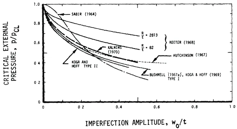
2.12 Imperfection-sensitivity of complete spherical shells (from Kaplan (1974)).. . . 25
3.1 Definition of wavy shell geometry showing also several control points. . . 28
3.2 Cross sections with (a) mirror-symmetry and (b) 4-fold symmetry. rq,i denotes the radial position of theithcontrol point in theqthquadrant. . . . . 29
3.3 (a) Wavy shell with perfect geometry,C0(r1,1, r1,2, ...); (b) imperfection shape based on critical buckling mode,µΦ, withµ= 10tfor clarity; (c) imperfect wavy shell,C+=C0(r1,1, r1,2, ...)+µΦ. 30 3.4 Schematic of equilibrium diagrams for geometrically perfect and imperfect shells, showing def-inition of limit loads. In the example shown the load-displacement curves for the perfect shell and the imperfect shell with negative imperfection turn back at the first limit load. . . 32
3.5 Critical buckling mode of reference (circular) cylindrical shell. . . 35
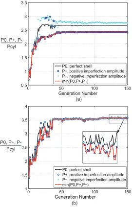
3.6 Evolution of buckling loads for mirror-symmetric wavy shells with (a)N = 11 and (b)N = 16. The loads are normalized by the buckling load of the perfect, reference cylindrical shell. . . 36
3.7 Cross-sections of mirror-symmetric wavy shells with (a)N = 11 and (b)N= 16. . . 37
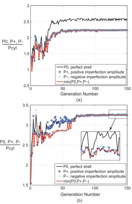
3.8 Evolution of buckling loads for 4-fold symmetric wavy shells with (a)N = 11 and (b)N = 16. For the case N = 16 P± is slightly lower than P0 after the 72nd generation. The loads are normalized by the buckling load of the perfect, reference cylindrical shell. . . 38
3.9 Cross-sections of 4-fold symmetric wavy shells with (a)N= 11 and (b)N = 16. . . 39
3.10 Components of mirror-symmetric wavy shells.. . . 40
3.11 Components of 4-fold symmetric wavy shells. . . 41
3.12 Buckling loads of geometrically perfect sinusoidally corrugated shells with corrugations of three different amplitudes. . . 43
3.13 Comparison of (a) knockdown factor and (b) critical stress of sinusoidally-corrugated shells and wavy shell designs obtained in Sections 3.2.3-3.2.4. . . 44
3.16 Revised version of Fig. 2.8 showing additional data points corresponding to mirror-symmetric
wavy shell design withN = 16, sinusoidally corrugated shells, and Aster shell. . . 48
3.17 Critical buckling modes of shells withL/Dof (a) 1.1, (b) 1.2, and (c) 2. . . 49
3.18 Evolution of buckling loads for mirror-symmetric shells withN = 16 andL/D= 2. The loads are normalized by the buckling load of the perfect, reference circular cylindrical shell with L/D= 2. . . 50
3.19 (a) Cross-section of optimal design. (b) Critical buckling mode of optimal design. . . 50
4.1 Mandrel made on a wire-cut machine. . . 54
4.2 Laminate and films that facilitate release of cured shell. . . 54
4.3 Lay-up. . . 55
4.4 The laminate is laid up on the mandrel. This figure shows that the laminate is kept on the mandrel surface by the tape. . . 55
4.5 Cured composite (a) wavy shell and (b) circular shell. . . 55
4.6 Glass and plastic cup for potting. . . 56
4.7 Fixture with mandrel, composite shell, flat glass, and plastic cup for potting. The epoxy has been poured in the plastic cup. . . 57
4.8 (a) Wavy shell and (b) circular shell with potted ends. . . 57
4.9 Coded and non-coded targets. . . 58
4.10 Camera setup for (a) defining a global coordinate system (step 1) and (b) measuring positions of non-coded targes (step 2). . . 59
4.11 Schematic of finding the best-fit position of measured shells. epis the normal distance between thepthmeasured point and the corresponding point on the perfect shell. . . . . 60
4.12 (a), (b), and (c) are thickness distributions of wavy shells 1, 2, and 3, respectively. . . 61
4.13 (a), (b), and (c) are mid-plane imperfection ratio (imperfection divided by nominal thickness) distributions of wavy shells 1, 2, and 3, respectively. . . 62
4.14 (a), (b), and (c) are the Fourier components of the mid-plane imperfections of wavy shells 1, 2, and 3, respectively.. . . 63
4.15 Abaqus models for (a) uniform axial load and (b) uniform end-shortening.. . . 65
4.16 Load versus end shortening curves for perfect shell and imperfect wavy shell 3. . . 67
4.17 Flow chart of the failure analysis on the critical region. . . 69
4.18 The ratio between the stress and the corresponding strength for each layer of laminate of wavy shell 1. Layer 1 is on the outer surface of the shell. . . 70
4.19 Experimental setup for compression tests. . . 71
4.20 Load-time curve for wavy shells. . . 72
4.22 Out-plane deformations of wavy shell 2 when the axial load was (a) 3.985 kN, (b) 9.536 kN,
and (c) 11.626 kN . . . 74
4.23 Three consecutive images recorded by the high speed camera when the shell was (a) before
collapse, (b) during collapse, and (c) after collapse. The initial failure region is in the rectangle
in (b). . . 74
4.24 Comparison of the critical regions between experiments (top) and simulations (bottom) for
wavy (a) shell 1, (b) shell 2, and (c) shell 3. The simulations show the axial compressive strain
fields. . . 75
4.25 Typical buckling shape for circular shells. . . 76
5.1 (a) Cross-section of corrugated cylindrical shell. (b) Schematic of a complete corrugation. ϕand
z are the circumferential and axial directions, respectively. The four edges of the corrugation are denoted as edges 1 to 4. . . 79
5.2 Schematic of two identical meshes coupled by the *MPC function in Abaqus. [S] and [C] are the sine and cosine terms in Eq. 5.12, respectively. Only the real part of the Bloch relation is
shown in this figure. . . 82
5.3 Flow chart of the algorithm of finding the critical buckling mode and load. . . 83
5.4 Schematic of possible post-buckling branches. B0is the bifurcation point corresponding to the
branch ofn= 0. . . 84
5.5 Critical end-shortening obtained from the modified Bloch wave method, nonlinear, and linear
full FEA models. . . 88
5.6 Critical buckling loads obtained from the modified Bloch wave method, nonlinear, and linear
full FEA models. . . 88
5.7 Buckling modes of the shell withN = 13 corrugations obtained from (a) modified Bloch wave method, (b) nonlinear full FEA model, and (c) linear full FEA model. . . 90
5.8 Buckling modes of the shell withN = 31 corrugations obtained from (a) modified Bloch wave method, (b) nonlinear full FEA model, and (c) linear full FEA model. . . 91
5.9 Buckling modes of the shell withN = 40 corrugations obtained from (a) modified Bloch wave method, (b) nonlinear full FEA model, and (c) linear full FEA model. . . 92
5.10 Computation time for the modified Bloch wave method, linear, and nonlinear full FEA models. 93
5.11 Schematic of stiffeners (from Hilburger et al. (2012b)). . . 93
5.12 Schematic of a unit cell used in the modified Bloch wave method. . . 94
5.13 Buckling modes of the stiffened shell obtained from (a) modified Bloch wave method, (b)
nonlinear full FEA model, and (c) linear full FEA model. . . 96
6.2 A second order geodesic sphere. Note that only half of the shell is shown in the figure for clarity.
(Image from www.instructables.com). . . 98
6.3 Schematic of subdividing a face of icosahedron into faces of a geodesic sphere. (a) A face of
icosahedron. (b) Second order subdivision. (c) Third order subdivision. . . 99
6.4 (a) Top view of a triambic icosahedron (from Wikipedia). (b) The solid lines correspond to the
folding pattern of an icosahedron, and the dash lines are projections of the edges of pyramids
on the faces of icosahedron. . . 100
6.5 Buckling pressures of triambic pyramids with various heights of pyramids.. . . 101
6.6 Buckling modes of (a) triambic icosahedron withH=−H0, (b) icosahedron, and (c) triambic
icosahedron withH = 1.75H0. Red regions represent outward deformation. . . 102
6.7 Parametrization of shell geometry. This figure is the 2D pattern of the bases of pyramids, and
only 8 triangular bases are shown here. . . 102
6.8 Evolution of (a) buckling pressures and (b) design variables during optimization 1. . . 103
6.9 Evolution of (a) buckling pressures and (b) design variables during optimization 2. Note that
the height is normalized byH0.. . . 104
6.10 Parametrization of shell geometry. This figure is the 2D pattern of the bases of pyramids, and
only 8 triangular bases are shown here. . . 105
6.11 Evolution of (a) buckling pressures and (b) design variables during optimization. Note that the
List of Tables
3.1 Buckling loads and computational time obtained from Abaqus models with various element sizes. 33
3.2 Dimensions of wavy shell designs . . . 34
3.3 Radial deviations,ri−R, (in mm) of control points of mirror-symmetric shells.. . . 37
3.4 Radial deviations of control points,ri−R, (in mm) of 4-fold symmetric shells. . . 39
3.5 Length of center line, knockdown factor, and critical stress for 180µm thick carbon-fiber com-posite shells with reference radius of 35 mm. . . 39
3.6 Peak wave number and bandwidth of wavy cylinder designs. . . 41
3.7 Sensitivity of knockdown factors to imperfection amplitude. . . 42
3.8 Knockdown factors and critical stresses for circular shell, Aster shell, and wavy shell, all made of nickel. . . 46
3.9 Buckling loads and knockdown factors of composite wavy shells with various lengths. . . 49
4.1 Measured thickness and imperfections of circular and wavy shells. µis the ratio between the imperfection amplitude and nominal shell thickness 180µm. . . 60
4.2 Summary of computed buckling loads for the wavy shells to be tested. µ is the imperfection amplitude divided by the nominal shell thickness,tnom= 180 µm. . . 66
4.3 Buckling loads based on measured thickness and mid-plane imperfection distributions. . . 66
4.4 Predicted and measured failure loads and knockdown factors for wavy shells. The buckling load of the perfect wavy shell was computed based on the uniform thickness of 166µm, which is the measured average thickness.. . . 72
4.5 Measured thickness and imperfections of circular shells. . . 76
4.6 Measured buckling loads and knockdown factors of circular shells.. . . 76
5.1 Dimensions of wavy shell designs . . . 86
5.2 Dimensions of stiffeners. The unit is in inches. . . 93
5.3 Buckling loads and computational time of stiffened shell. . . 94
Chapter 1
Introduction
1.1
Overview
Cylindrical shells have been widely used over decades in many engineering fields such as civil, oil, marine, and aerospace industries, etc. For example, storage tanks, as shown in Fig.1.1(a), are the most commonly seen cylindrical shells, and cylindrical pipelines are key structural components in oil and natural gas industry. Due to the lightness and high load-carrying capability of cylindrical shells, they have been extensively used as aerospace structures such as airplane fuselages and rocket shells, as shown in Fig.1.1(b) and (c).
(a)
(b)
(c)
Figure 1.1: (a) Water storage tank (image credit: CST Industry). (b) Boeing 787 composite fuselage. (c) Space Shuttle Atlantis (image credit: NASA/KSC).
Spherical shells also have very wide structural applications in engineering. For example, spherical shells can be used as storage tanks, as seen in Fig. 1.2 (a); the spherical submarine in Fig. 1.2 (b) is a typical example of spherical shells under hydrostatic pressure. A portion of a complete spherical shell, i.e., spherical cap, is also often used. The most common applications of spherical caps are concrete roofs such as the roof of the Kresge Auditorium in Fig.1.2(c).
(a) (b) (c)
Figure 1.2: (a) Spherical storage tanks (image credit: BBB Tank Services). (b) Triton submarines (image credit: Sandra Edwards/South Florida Dive Journal). (c) MIT Kresge Auditorium (from Wikipedia). Its concrete roof is one-eighth of a complete sphere.
is an important and sometimes critical consideration in designing thin cylindrical and spherical shells. Among the destabilizing loading conditions, axial compression for cylindrical shells and external pressure for spherical shells are the most destructive ones because their buckling is extremely sensitive to geometric imperfections. Typical examples of axially compressed cylindrical shells and externally pressurized spherical shells are rocket shells under self-weight and submarine pressure hulls under hydrostatic pressure, respec-tively. A small geometric imperfection can drastically reduce the buckling loads of those shells, significantly impairing their mass efficiency in carrying loads. This extreme imperfection-sensitivity has been one of the major obstacles in designing axially compressed cylindrical shells and externally pressurized spherical shells.
1.1.1
Axially Compressed Cylindrical Shells
Motivated by the development of aerospace industry, axially compressed cylindrical shells have been exten-sively studied since the space age. Large discrepancies between theoretically predicted and experimentally measured buckling loads for axially loaded cylindrical shells were first observed in the 1930s. It was found that thin cylindrical shells under axial compression may buckle at loads as low as only 20% of the theo-retically predicted buckling loads (Brush and Almroth,1975). It was subsequently established in the 1940s that this disagreement between theories and experiments is due to the extreme imperfection-sensitivity of buckling of cylindrical shells under axial compression.
Closely stiffened cylindrical shells, shells reinforced by stringers, corrugations, and rings, as shown in Fig.1.3, are used to mitigate the severe imperfection-sensitivity. It has been found that the knockdown factors of closely stiffened shells could be between 0.7 and 0.95, indicating a much lower imperfection-sensitivity than unstiffened monocoque cylindrical shells (Card and Jones,1966). This architecture is currently established as the premiere efficient aerospace structure (Singer et al.,2002b). However, stiffened shells are still sensitive to imperfections, although the sensitivity is not as extreme as monocoque cylindrical shells. It should also be noted that the stiffened cylindrical shells are very expensive due to their complex manufacturing processes.
(a)
(b)
Figure 1.3: (a) Saturn V. (image credit: Ron Crain). (b) A corrugated graphite-epoxy ring-stiffened cylin-drical shell (Davis,1982).
1.1.2
Externally Pressurized Spherical Shells
The buckling behavior of spherical shells under external pressure has been extensively investigated since the 1960s. Both theoretical and experimental studies have confirmed the severe imperfection-sensitivity of externally pressurized spherical shells. The analytical predictions obtained byHutchinson(1967) andKoga and Hoff(1969) showed that an imperfection with amplitude of half shell thickness could drastically reduce the buckling pressure by 50% to 60%. The experiments performed by Krenzke (1962) showed that the measured buckling pressure could reach only 50% to 70% of the predicted values of perfect spherical shells. Empirical knockdown factors are used in practice to design spherical shells under external pressure; see referencesNASA-SP-8032(1969) for spherical caps andKrenzke and Kiernan(1963) for complete spherical shells. Similar to the knockdown-factor method of cylindrical shells, using the empirical knockdown factors of spherical shells leads to overly conservative and heavy shells which are still very sensitive to imperfections (Nemeth and Starnes,1998).
directions. The analytical and numerical studies byOry et al.¨ (2002) showed that stiffened spherical shells under hydrostatic pressure could still be rather sensitive to imperfections. Therefore, considerable theoretical and experimental studies are required in order to find the efficient stiffening configurations.
1.2
Objective and Scope
The two main methods of designing axially compressed cylindrical shells and externally pressurized spherical shells have drawbacks. First, the knockdown-factor method essentially provides conservative safety factors without changing the behavior of shell buckling. Second, although stiffening cylindrical shells by equally spaced stringers, rings, and corrugations can mitigate the imperfection-sensitivity, stiffened cylindrical shells are still sensitive to imperfections and are very expensive. In addition, the effects of stiffening spherical shells are not clear.
The objective of this dissertation is to propose novel methods of designing imperfection-insensitive axially compressed cylindrical shells and externally pressurized spherical shells that have high load-carrying capa-bility. Conventional cylindrical and spherical shells have axial symmetry, high-order rotational symmetry, or spherical symmetry. The methods proposed in this dissertation use structural optimization to search for optimal symmetry-breaking shapes that maximize the critical buckling loads and at the same time reduce imperfection-sensitivity. The behavior of the novel symmetry-breaking shells designed through the proposed methods is fundamentally different from the highly symmetric shells obtained from the knockdown-factor method and stiffening method.
This dissertation is mainly focused on axially compressed cylindrical shells. The method of designing imperfection-insensitive axially compressed cylindrical shells was first developed and then used to produce several composite and metal shells. Experimental studies were preformed on a design of composite shell in order to validate the method. A fast computational method for buckling analysis of axially loaded stiff-ened/corrugated cylindrical shells was developed, and could be potentially used to reduce the computational costs of optimization. The idea of breaking symmetry was then applied in designing imperfection-insensitive metal spherical shells under external pressure. All the shells presented in this dissertation were assumed to be linearly elastic.
1.3
Layout of Dissertation
externally pressurized spherical shells.
Chapter3first describes a method for obtaining imperfection-insensitive axially loaded cylindrical shells. Several symmetry-breaking shells (wavy shells) designed through the method are then presented. The results are then analyzed and compared to other alternative shells, including sinusoidally corrugated shells and Aster shell. The mass efficiency of wavy shells is then calculated and compared to currently existing stiffened shells. Chapter 4 presents experimental studies of the best composite wavy shell obtained in Chapter 3. The chapter begins with a method of making composite wavy shells. A novel method of measuring full-field geometric imperfections is then presented. Based on measured imperfections, the experimental behavior of the wavy shells is predicted. The last part of the chapter shows the measured experimental behavior of the wavy shells.
Chapter5presents a highly efficient computational tool for predicting the onset of buckling of corrugated or stiffened cylindrical shells under axial compression. The computational tool is a modification of the traditional Bloch wave method for two or three dimensional infinite structures. The chapter first explains how the Bloch wave method is modified for corrugated and stiffened cylindrical shells. The numerical implementation of the modified method, including the finite element implementation and algorithm, is then described. Several numerical examples are then analyzed to validate the modified Bloch wave method. The results and computational time of the modified Bloch wave method are then compared to linear and nonlinear finite element analyses based on full detailed finite element models.
Chapter 2
Background and Literature Review
This chapter consists of two parts: literature reviews of axially compressed cylindrical shells and exter-nally pressurized spherical shells. There is a huge body of literature on the buckling of linear-elastic thin cylindrical and spherical shells. This chapter is focused on the essential background to the present study. The interested reader is referred to the extensive reviews compiled byBrush and Almroth(1975),Elishakoff
(2012),Hutchinson and Koiter(1970),Jones(2006),Singer et al.(2002a),Singer et al.(2002b), andBushnell
(1985).
2.1
Reviews of Axially Compressed Cylindrical Shells
2.1.1
Theories and Design Methods
2.1.1.1 Effects of Imperfections on Cylindrical Shells
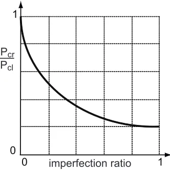
The first major contribution to the present understanding of the effects of initial imperfections on the buckling of circular cylindrical shells was made by Von K´arm´an and Tsien (1941), who analyzed the postbuckling equilibrium of axially compressed cylindrical shells. Donnell and Wan (1950) analyzed initially imperfect cylindrical shells and obtained equilibrium paths as sketched by the dash line in Fig.2.1, whereP andPcl are the compressive load and the classical bifurcation buckling load, respectively. Figure2.1shows a sharply dropping second equilibrium path and thus indicates that an initially imperfect shell buckles at the limit point B instead of reaching the bifurcation point A.Koiter (1963) analyzed the influence of axisymmetric imperfections coinciding with the axisymmetric buckling mode of a perfect cylindrical shell. His results, summarized in Fig. 2.2, show that imperfections with even a small amplitude can dramatically reduce the buckling load.
A
B
O Pcl
Pcr
axial shortening P
Figure 2.1: Sketch of equilibrium paths for axially compressed, geometrically perfect cylindrical shells (solid line, fromVon K´arm´an and Tsien(1941)) and imperfect cylindrical shells (dash line, fromDonnell and Wan
(1950)).
0
0 1
Pcr
Pcl
imperfection ratio
1
buckling mode associated with the first bifurcation point:
λ0≡ P Pcl
= 1 +a1δ+a2δ2+..., (2.1)
where a1, a2, ...are constants and δ is a measure of the lateral displacement amplitude. This solution is shown by means of solid lines in Fig.2.3. In case Ia1̸= 0 and for small values ofδthe secondary equilibrium path is approximated by a straight line. For the other two cases a1 = 0, resulting in quadratic secondary equilibrium paths: a2<0 for case II and a2>0 for case III.
The corresponding equilibrium paths for imperfect structures are shown by dash lines in the figure. λ± are ratios between the buckling loads of imperfect structures with positive/negative imperfections and the perfect structure. Cases I and II represent structures that aresensitive to imperfections, because the buckling loads of the imperfect structures (λ− for case I andλ± for case II) are lower than 1. In case I different signs of imperfections lead to different types of imperfection-sensitivity.
1 1
1 λ0
λ+ λ−
δ δ δ
Figure 2.3: Three types of post-buckling equilibrium paths for perfect and imperfect structures, fromBrush and Almroth(1975) andKoiter(1945).
2.1.1.2 Design of Cylindrical Shells Against Buckling
The current approach for the design of axially compressed monocoque cylindrical shells against buckling accounts for buckling load reductions due to imperfections through the knockdown-factor method. The actual buckling load of a cylindrical shell is estimated from:
Pcr=γPcl (2.2)
whereγ is the knockdown factor andPcl is given by (Brush and Almroth,1975):
Pcl=
2πEt2
√
3(1−ν2), (2.3)
whereE,ν, andtare the Young’s modulus, Poisson’s ratio, and shell thickness, respectively.
dataset of experimentally derived knockdown factors and hence can be used to predict the buckling load using Eq.2.2.
Designs obtained from the knockdown factor method are required to achieve a theoretical buckling load Pclhigh enough that the reduced buckling loadPcrobtained from Eq.2.2satisfies the design requirements. Fundamentally, the knockdown-factor design method accepts highly imperfection-sensitive shell designs, but limits the maximum load that can be applied to keep them safe.
R/t 1.0
0.6
0.2
0 0.8
0.4
0 400 600 800
γ
16 1
t R − γ = 1−0.901(1−e )
Figure 2.4: Experimentally measured values of knockdown factor and empirically defined lower bound curve, as a function of the radius to thickness ratio (Jones,2006).
An alternative structural form to the imperfection-sensitive monocoque cylinder is the stiffened cylin-drical shell. Although it is difficult to make a general comparison, as there are many different potential configurations for the stiffeners, as an example it can be noted that experiments on 12 longitudinally stiff-ened cylindrical shells with internal or external, integral or Z-stiffeners provided knockdown factors in the range 0.7 to 0.95, indicating a much lower imperfection-sensitivity than monocoque cylindrical shells (Card and Jones,1966).
2.1.1.3 Manufacturing Imperfection Signature Method
The empirically derived lower bound on the knockdown factor in Fig. 2.4 was derived from many tests conducted over a long period of time and recently it has been argued that the manufacturing, loading, and boundary conditions for this large set of shells are not sufficiently well-known to provide a rational basis for modern design. Also, most data points correspond to metallic shells, whereas fiber-reinforced composite shells are not well represented (Jones,2006;Nemeth and Starnes,1998). Hence, it has been argued by several authors that the knockdown-factor approach tends to provide overly conservative designs because it allows for the worst possible imperfections, which is not a reasonable assumption for modern, precision-made shells. An emerging alternative design approach is based on the “signature” of the manufacturing imperfection, which is a statistical representation of geometric imperfections based on measurements (Rotter et al.,1992;
is then applied in the analysis to accurately predict the actual buckling load. Hilburger et al.(2006) obtained the buckling loads of six graphite-epoxy cylindrical shells subject to combined axial compression and torsion by using five imperfection shapes, including the actual measured imperfections of test specimens, mean imperfection shape, mean imperfection shape plus or minus one standard deviation, and the critical-buckling-mode imperfection shape. The predicted and measured buckling loads of a composite shell with an axially-stiff laminate [±45/02]sare summarized in Fig.2.5, where it should be noted that the measured amplitude of imperfection was in the range +1.27t to−1.54t.
1.25
1.00
0.75
0.50
0.25
0
-1.5 -1.0 -0.5 0 0.5 1.0 1.5 Pcl
Pcr
Tcr/ Tcl Perfect Mean −σ
Mean +σ Actual measured imperfections
Measured buckling
Eigen-mode imperfection
SP-8007
Figure 2.5: Predicted buckling loads for axially stiff shells under combined axial compression and torsion (Hilburger et al.,2006). Pcr andTcr are the axial and torsional buckling loads of imperfect shells; Pcl and Tcl are the corresponding bifurcation buckling loads of perfect shells; σ is the standard deviation of the imperfection.
Figure2.5shows that the buckling loads predicted using an imperfection based on the critical eigenmode, or using the SP-8007 data (Peterson et al., 1965) are both much lower than the measured buckling load, indicating that using these two approaches can lead to rather conservative designs. Note that the buckling load predicted with the imperfection-signature approach closely matches the measurements.
2.1.1.4 Alternative Approaches: Aster Shell, Pseudo-Cylindrical Shell, and Ramm’s Method
Figure 2.6: Cross-sections of dominant eigenmode of circular shell (solid and dashed arcs) and Aster shell (solid line) withR/t= 490.
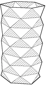
FollowingYoshimura(1951),Knapp(1974,1977) proposed another intuitive shell design, pseudo-cylindrical shell, which approximates the buckled pattern under axial compressing by using flat polyhedral elements, as shown in Fig.2.7. This concept is based on the assumption that, if a cylindrical shell is fabricated following the pattern in Fig.2.7, it is more stable than the imperfection-sensitive circular geometry. However, Knapp did not study the imperfection-sensitivity of pseudo-cylindrical shells. Simulations carried by the author of this thesis show that the pseudo-cylindrical shell has a high knockdown factor of 0.9 and its buckling load is 30% lower than the perfect circular shell with the same radius, length, and material.
Figure 2.7: A buckled pattern approximated by flat polyhedral elements (from Yoshimura(1951)).
A general shape optimization method for thin shell structures was proposed byReitinger et al.(1994) and
Reitinger and Ramm(1995). Instead of considering only the buckling loads of perfect candidate structures, as in conventional structural optimization, these authors considered both perfect and imperfect structures in the evaluation of the objective function. This fundamental difference avoids convergence towards highly imperfection-sensitive designs.
Finally, the minimum amongP0 andPcr is chosen as the value of the objective function.
Applications of this method to the design of concrete shell roofs, stiffened panels, and free-form shells were presented byReitinger and Ramm (1995);Ramm and Wall (2004).
2.1.1.5 Efficiency Chart
Quantitative comparisons of different structural designs require the use of suitable metrics. In the present case, the buckling performance of monocoque, stiffened, or any other kinds of cylindrical shells can be compared by considering the weight and load indices (Peterson,1967;Agarwal and Sobel,1977;Nemeth and Mikulas,2009), which are defined as follows:
Weight index : W AR
Load index : Nx R
(2.4)
HereW,A, andRare the total weight of the shell, the surface area, and radius of the cylinder, respectively, and
Nx= Pcr
2πR (2.5)
denotes the (axial) critical buckling stress resultant. The surface area of the shell isA= 2πRL, whereLis the length of the cylinder. Note that the weight and load indices are dimensional, this is the form commonly used by shell designers.
For circular monocoque cylindrical shells, the relation between weight and load indices can be found as follows. Begin by substitutingW =ρAtinto the weight index expression, which gives
W AR =
ρt
R (2.6)
Then, solve Eq.2.3fortto obtain:
t=
√
Pcl √
3(1−ν2)
2πE (2.7)
Then, substitute Eq.2.7into Eq.2.6and replacePcr/γ forPcl, from Eq.2.2, to obtain:
W AR=
ρ R
√
Pcr √
3(1−ν2)
2γπE (2.8)
Further substitution of 2πRNx forPcr , from Eq.2.5, and simplification gives:
W AR=ρ
√√
3(1−ν2) γE
Nx
Figure 2.8 shows a plot ofW/AR vs. Nx/R. The inclined straight line in the figure represents perfect (γ= 1) monocoque aluminum shells; the horizontal line corresponds to lightly-loaded shells which are subject to a minimum thickness constraint. The data points included in the plot represent (a) shells with integral-orthogonal stiffeners under axial compression (Katz, 1965), (b) z- and integrally-longitudinally stiffened shells under axial compression (Card,1964a), (c) a corrugated graphite-epoxy ring-stiffened cylinder under bending (Davis,1982), (d) ring-stiffened corrugated cylinders under axial compression (Peterson,1967), and (e) z-stiffened shells subject to bending (Card, 1964b). Note that for structures subjected to bending the critical axial stress resultant used in the calculation of the load index was the peak axial stress resultant due to the critical bending moment, obtained from simple bending theory.
Shells closer to the right-bottom corner of the chart are the most efficient, as they can carry larger loads using less material. The chart shows that most stiffened cylindrical shells have higher efficiency than even perfect monocoque circular cylindrical shells. However, it should be noted that the reduced imperfection-sensitivity of stiffened cylindrical shells is countered by their complex manufacturing process. Machining from thicker stock and special forgings are the main manufacturing methods for metallic shells (Singer et al.,
2002b). In 1986 the cost of a 320 mm diameter steel shell stiffened in one direction was on the order of $3,500, and of $15,000 for a similar, orthogonally stiffened shell (Scott et al.,1987;Singer et al.,2002b).
Stiffened (a) Stiffened (b) Stiffened (c) Stiffened (d) Stiffened (e) Monocoque
10-3
W AR
lb in3
10-4
10-5
100 101 102 103
Nx
R lb in2
Figure 2.8: Performance chart for stiffened cylindrical shells described in Section 2.1.1.5(data provided by Dr. M.M. Mikulas) and including plot of Eq.2.9for perfect (γ= 1) monocoque cylinders.
2.1.2
Experimental Methods
2.1.2.1 Manufacture of Cylindrical Shells for Research
Electroforming was one of the main methods of making monocoque metal cylindrical shells for research in the 1960s; see for examples Almroth et al. (1964); Arbocz and Babcock Jr (1968); Babcock (1962);
conductive paint in electrolyte baths. The shells were removed from mandrels by melting the wax after plating. Extreme care was required to avoid damaging or warping the shells because the wax significantly expanded when it was heated to the melting point (Babcock,1962). Electroformed shells usually have large imperfections due to the initial stresses generated in the plating processes (Singer et al.,2002b). In the 1980s and 90s, Jullien and his co-workers (Jullien and Araar,1991;Araar,1990) significantly improved the quality of electroformed shells by plating cooper or nickel on accurately machined duraluminum mandrels which were then chemically dissolved for separation of shells. Despite those improvements, it has been warned by Singer et al. (2002b) that electroforming remains a very difficult method that requires high skill and experience to produce consistently good specimens.
Machining from thicker stock and special forgings is usually used to make monocoque metal cylindrical shells when high accuracy is required and it is also the primary method to make high-quality integrally stiffened cylindrical shells (Singer et al., 2002b). For non-integrally stiffened cylindrical shells, stiffeners are welded or riveted to unstiffened cylindrical shells or flat plates which are then rolled onto a cylindrical mandrel; see for exampleDowling and Harding(1982) andCard and Jones(1966). The fabrication processes of stiffened shells are very expensive. In 1986 the cost of a 320 mm diameter steel shell stiffened in one direction was on the order of $3,500, and of $15,000 for a similar, orthogonally stiffened shell (Scott et al.,
1987;Singer et al.,2002b).
Composite materials have been increasingly used in aerospace structures because of their high stiffness, high strength, and low density. The fabrication procedure of composite cylindrical shells for research usually consists of a laminate lay-up process and an autoclave curing process. Graphite-epoxy shells made by
Hilburger et al. (2006) are typical examples of small-scale monocoque composite cylindrical shells, which were laid up on a cylindrical mandrel, vacuum bagged and cured in an autoclave. Large composite shells can also be assembled from cylindrical panels which are warped from initially flat panels. For example, the 3-meter-diameter graphite-epoxy corrugated cylindrical shell in Johnson (1978) was assembled from three segments which were laid up and cured on a flat corrugated mold and then wrapped to the cylindrical shape. This approach is feasible for fabricating composite shells with flexible thin walls and a relatively large radius (Johnson,1978).
2.1.2.2 Methods of Measuring Imperfections
The three-dimensional survey is currently the main method of measuring shell imperfections. A typical 3D survey instrument consists of a scanning rig and a data recording system (Verduyn and Elishakoff, 1982;
Shell imperfections are calculated by comparing the scanned shell surface to an imaginary perfect cylinder. The position of the perfect cylinder is determined by finding the best-fit cylinder to the measured data (Singer et al.,2002b). The method of least squares is usually used to minimize the sum of the squares of the normal distances from the measured points to the imaginary perfect cylinder by varying the rigid-body translations and rotations of the perfect cylinder (Arbocz and Babcock Jr,1968;Cartalas et al., 1990;Hilburger et al.,
2006). The solution of the minimization problem is the position of the best-fit perfect cylinder. The radial deviations of the measured surface with respect to the best-fit perfect imaginary cylinder are computed as imperfections.
Measured imperfections can be represented by Fourier series in order to analyze and compare the compo-nents of different imperfections. A commonly used form of Fourier series for decomposing initial imperfections is the half-wave cosine Fourier expansion (Arbocz and Babcock Jr,1968;Singer et al.,2002b):
ω(x, θ) =tnom M ∑ k=0 M ∑ l=0 cos(kπx
L )[Aklcos(lθ) +Bklsin(lθ)] (2.10)
where L and tnom are the shell length and nominal thickness, respectively. x and θ denote the axial and circumferential coordinates. k and l are the wave numbers of axial half-cosine waves and circumferential full-waves, respectively. The Fourier coefficients are given byCartalas et al.(1990):
A00= 1 2πLtnom
∫ L
0
∫ 2π
0
ω(x, θ)dx dθ
Ak0= 1 πLtnom
∫ L
0
∫ 2π
0
ω(x, θ)cos(kπx
L )dx dθ, k >0
A0l= 1 πLtnom
∫ L
0
∫ 2π
0
ω(x, θ)cos(lθ)dx dθ, l >0
Akl = 2 πLtnom
∫ L
0
∫ 2π
0
ω(x, θ)cos(kπx
L )cos(lθ)dx dθ, k >0, l >0
Bk0= 0, k≥0
B0l= 1 πLtnom
∫ L
0
∫ 2π
0
ω(x, θ)sin(lθ)dx dθ, l >0
Bkl = 2 πLtnom
∫ L
0
∫ 2π
0
ω(x, θ)cos(kπx
L )sin(lθ)dx dθ, k >0, l >0
(2.11)
The amplitude of a component of an imperfection can be computed by:
ξk,l= √
A2 kl+B
2
kl (2.12)
2.1.2.3 Measurement of Shell Deformation and Recording of Buckling Behavior
and Otomo (1973); Araar(1990); Limam et al.(1991). The loads in those experiments were incrementally increased and stopped at each value of interest so as to scan the shell surface. Strain gages were usually used to measure shell strains. Recently, three-dimensional digital image correlation (DIC) systems have been utilized to measure shell deformations in buckling experiments of both small-scale (Wu et al., 2013) and large-scale shells (Hilburger et al.,2012a). The DIC is a non-contact technique that can measure shell deformations and strains without interrupting the testings. They can also provide full-field high-resolution measurements at a much higher speed than three-dimensional survey systems.
High-speed photography is required in order to record the behavior of shells during buckling because buckling is a very short dynamic procedure. So far most of the high-speed photography recordings for shell buckling experiments used film speeds of 1500 to 8000 frames per second (Singer et al.,2002b). Although modern high-speed cameras can operate at a very high film speed, the corresponding total recording time is very short. For example, the Phantom V310 high-speed camera (Vision Research, 2014) can only record for approximately 2 seconds at the film speed of 6000 frames per second with a resolution of 0.5 megapixels. Thus the timing for triggering high-speed cameras is very challenging and requires extreme care to capture the onset of buckling. However, if the shells can buckle at virtually the same load, the high-speed camera can be synchronized with the initiation of buckling (Singer et al.,2002b).
2.1.3
Computational Methods
2.1.3.1 Overview on Methods for Buckling Analysis of Corrugated/Stiffened Cylindrical Shells
Although current commercial finite element codes allow us to analyze the buckling behavior of corrugated and stiffened cylindrical shells, detailed simulations are computationally intensive. Typically, the overall dimensions of a cylindrical shell are much larger than the space between stiffeners or the wavelength and amplitude of corrugations. For example, a corrugated shell designed by Johnson (1978) had a diameter of 3 m, with a corrugation wavelength and amplitude of only 11.4 and 1.1 cm, respectively. Therefore, it would be necessary to use very small shell elements to accurately mesh the shell geometry and hence to obtain accurate results, leading to lengthy computations. This high computational effort has been the major constraint on the use of finite element analysis in the optimization of corrugated/stiffened shells (Bisagni and Vescovini,2009).
A variety of methods have been introduced to reduce the computational effort required for the buckling analysis of corrugated and stiffened shells. A common approach is to replace their actual shell cross-section with a smooth shell surface that has equivalent stiffness properties. The smeared-out method is a simple method to compute the equivalent properties, and it has been used in the buckling analysis of both corrugated and stiffened shells since the 1960’s (Block et al., 1965; Amazigo and Hutchinson, 1967; Simitses, 1971;
anisotropic shell (Calladine,1989).
Motivated by recent studies on corrugated morphing wings, various homogenization methods have been developed to obtain more rigorous equivalent stiffness properties than those provided by the smeared-out method, see Refs.Yokozeki et al.(2006);Thill et al.(2010);Briassoulis(1989);Liew et al.(2007);Xia et al.
(2012);Ye et al.(2014). In the homogenization methods strains and curvatures are applied independently on a single corrugation (unit cell) and, exploiting the periodicity of corrugated shells, the corresponding reaction forces and moments at the boundaries of the unit cell are computed either analytically or numerically. The equivalent stiffness properties are then calculated through the load-displacement relations.
Both the smeared-out and homogenization methods are effective in reducing significantly the computa-tional effort required by a finite element analysis because a much coarser mesh can be utilized, due to the simple geometry of the equivalent shells. However, these two methods are valid only when the buckling of the shell is global, i.e., only if the wavelength of the buckling mode is much larger than the wavelength of the corrugations or the space between stiffeners (Calladine,1989;Bisagni and Vescovini,2009). These methods cannot be used to capture local skin or stiffener buckling or to calculate stresses in the shell (Lamberti et al.,
2003).
An alternative approach to the buckling and vibration analysis of corrugated and stiffened shells was developed in the 1980s by Williams and co-workers. These authors developed a stiffness matrix method that treated a shell as an assemblage of flat plates connected along their common longitudinal edges (Wittrick and Williams, 1974; Anderson et al., 1983; Williams and Anderson, 1983; Williams et al., 1990). In this method, the stiffness matrix for each plate is computed from the flat plate theory, and the buckling loads and modes are obtained by solving an eigenproblem. The program VIPASA was developed based on the stiffness matrix method, and it was found that VIPASA was much more efficient than general-purpose finite element programs (Singer et al.,2002b;Williams et al.,1990). VIPASA can analyze both flat and cylindrical corrugated and stiffened shells.
A unique feature of the stiffness matrix method is that, based on the periodicity of corrugated or stiff-ened shells, the buckling mode of a repeating portion can be expressed as a product of a complex-valued exponential term times the buckling mode of any repeating portion (Williams,1986a,b). This relation makes it possible to condense the full stiffness matrix of the whole shell into a smaller matrix related to only a single repeating portion. However, this method can only analyze corrugated/stiffened shells consisting of flat plates. Shells with curved walls, e.g., sinusoidally corrugated shells, must be approximated by a series of flat panels. In addition, it should be noted that the buckling modes are assumed to vary sinusoidally along the corrugations/stiffeners in this method. Therefore, this method could provide inaccurate results if the shells are short and/or clamped in the longitudinal direction.
Triantafyllidis and Schraad,1998). Their method has been one of the major tools for the buckling analysis of cellular structures such as honeycombs (Lpez Jimnez and Triantafyllidis, 2013), porous solids (Bertoldi et al.,2008), and foams (Gong et al.,2005). The Bloch wave method is based on the fact that the buckling modes of an infinitely periodic structure follow the form of the Bloch wave propagation, which is the product of a complex-valued plane wave exponential term times a function with the periodicity of one repetitive unit cell (Kittel and McEuen, 1976). The buckling loads and corresponding eigenmodes can be computed by performing eigenvalue analyses on a single unit cell whose boundaries are coupled by the Bloch relations rather on the whole structure, resulting in a significant reduction of computational effort.
2.1.3.2 Stiffness Matrix Method
A buckling problem can be expressed as an eigenvalue problem:
Kc(λc) ˜Uc= 0 (2.13)
where Kc is the tangent stiffness matrix of the complete structure, ˜Uc is its eigenvector, which is also the buckling mode of the structure, andλc is the buckling load corresponding to the buckling mode ˜Uc.
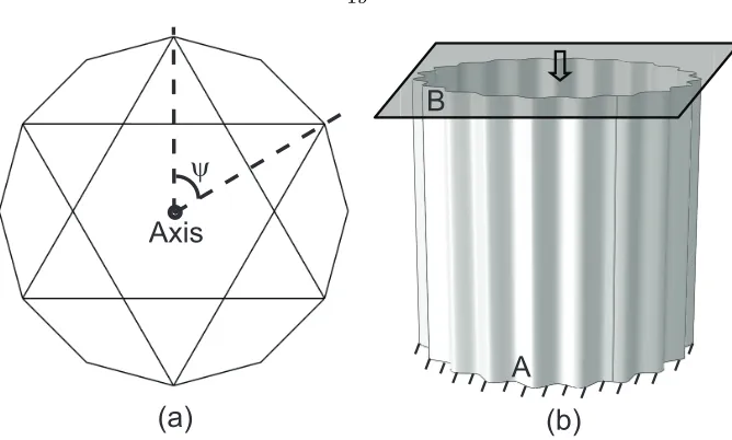
For a rotationally periodic structure, such as the ones shown in Fig. 2.9, with N repeating portions, ˜Uc can be partitioned intoN subsets:
˜
Uc= [ ˜U1,U˜2,U˜3, ...,U˜N]T (2.14)
where ˜Uq is the eigenvector of theqthportion of the structure. The stiffness matrix of a rotational periodic structure has the following form (Williams,1986a):
Kc =
K1 K2 K3 . . . KN
KN K1 K2 . . . KN−1
KN−1 KN K1 . . . KN−2 ..
. ... ... ... ... K2 K3 K4 . . . K1
(2.15)
whereKq is the stiffness matrix corresponding to theqthportion of the structure. Let the number of degrees of freedom of each repeating portion beJ, then Kq is aJ×J matrix.
Hence, Eq.2.13can be written as a set ofmequations:
ΣNq=1KqU˜m+q−1= 0, m= 1,2,3, ...N (2.16)
where
˜
Axis
ψ
(a)
(b)
A
B
Figure 2.9: (a) Rotationally periodic 2D truss structure with 6 repeating portions, ψ = 2π/6 is the angle subtended by the repeating portion. (Williams, 1986b) (b) Rotationally periodic corrugated shell subject to axial compression. The top edge “B” is clamped to a rigid plate. The boundary conditions on all nodes along edges “A” or “B” are identical.
The most general solution to Eqs.2.16and2.17is (Williams,1986a)
˜
Uq = ˜U1exp[i(q−1)nψ], n= 0,1,2,3, ...N (2.18)
with i =√−1, n = 0,1,2, ..., N, and ψ = 2π/N. Substituting Eq. 2.18into Eq. 2.16 and dividing it by exp[imnψ], we can formally reduce the set of mequations to the single equation:
(ΣNq=1Kqexp[i(q−1)nψ]) ˜U1= 0, n= 0,1,2,3, ...N (2.19)
which still needs to be solved to for each value ofnin order to find the smallest value ofλc.
It should also be noted that, because it is equivalent to define the buckling modes in either an anti-clockwise or anti-clockwise sense around the structure,
exp[i(q−1)(N−n)ψ] = exp[−i(q−1)nψ] (2.20)
nand N−nare not independent and the range of ncan be reduced ton= 1,2,3, ...{N/2}, where{N/2} is the largest integer no larger thanN/2.
Thus it has been shown that the eigenvalue problem in Eq. 2.13, posed in terms of the tangent stiffness matrix of the complete structure,Kc, is equivalent to{N/2}+ 1J-dimensional eigenvalue problems posed in terms of the ΣNq=1Kq(λc) exp[i(q−1)nψ], whereJ is the size of the stiffness matrix for the repeating portion of the structure.
imaginary parts of ˜Ui are possible buckling modes. Whenn = 0 orn=N/2 for even N, the exponential term in Eq.2.18is a real value and hence there is only one buckling mode corresponding to these two cases. The critical buckling load is the lowest one among the buckling loads for alln’s.
λcrit= min n=0,1,...,{N/2}
(λc(n)) (2.21)
It is common for rotationally periodic structures to have “axis nodes”, i.e., nodes shared by all the repeating portions or have the same translational and rotational deformation with respect to the axis. For example, stiffened or corrugated cylindrical shells subject to axial uniform end-shortening have “axis nodes” on their two ends, as shown in Fig.2.9(b). Let ˜UZq be the displacement w.r.t axis Z of the “axis nodes” of theqthportion, and substitute it into Eq.2.18:
˜
UZq = ˜UZ1exp[i(q−1)nψ], n= 0,1,2,3, ...{N/2} (2.22)
Because the nodes are “axis nodes”, ˜UZq must satisfy ˜UZq = ˜UZ1. Therefore, ˜UZq is always zero for n >0.
2.1.3.3 Bloch Wave Method
The Bloch wave method is a robust and efficient way of predicting the onset of buckling for 2-dimensional and 3-dimensional infinitely periodic structures (Geymonat et al., 1993; Triantafyllidis and Schnaidt,1993;
Triantafyllidis and Schraad,1998; Gong et al., 2005;Lpez Jimnez and Triantafyllidis, 2013;Bertoldi et al.,
2008). In this section we use a two-dimensional, infinitely periodic structure, as shown in Fig.2.10, to briefly review the Bloch wave method.
n1=0.5 n2=0.5
(a)
(b)
λ
λ
c
y
x
Figure 2.10: (a) Schematic of a 2D infinitely periodic porous structure subject to compression iny-direction. (b) A buckling mode and its corresponding buckling loadλc.
load λc, the original periodicity could be broken and the new repeating pattern could involve several unit cells. Fig.2.10(b) shows a buckling mode with a periodicity of 2 unit cells in both x- and y-directions. It has been proved that the buckling modes of a 2-dimensional infinite periodic structure have the following form (Geymonat et al.,1993;Triantafyllidis and Schnaidt,1993;Triantafyllidis and Schraad,1998):
˜
Uc(x, y) =Pu(x, y) exp[2πi( n1 L1
x+n2 L2
y)] (2.23)
where Lj and nj, j = 1,2 are respectively the lengths of the unit cell and the wave numbers. ˜Uc denotes the displacement of the complete infinite structure. Pu(x, y) is a periodic function with a periodicity of one unit cell:
Pu(x, y) =Pu(x+m1L1, y+m2L2) (2.24)
wherem1 andm2 are integers. Note that bothPu and ˜Uc are complex-valued functions.
The exponential term in Eq.2.23is essentially a wave propagation term that controls the propagation of Pu. For example, ifn1= 0.5 andn2= 0.5, the imaginary part of the exponential term follows the sinusoidal waves, as shown in Fig. 2.10 (b), whose wavelength is 2 unit cells in bothx- and y-directions. Since the periodicity of Pu is one unit cell, the buckling mode corresponding to n1 =n2 = 0.5 has a periodicity of two unit cells in bothx- andy-directions. Therefore, each value for the wave numbern1 orn2 represents a buckling mode for the structure in Fig.2.10(a). Eq.2.23is also called the Bloch wave propagation function and is what the Bloch wave method is named after.
The buckling problem of the complete infinite structure can be written as an eigenvalue problem:
Kc(λc) ˜Uc= 0 (2.25)
where Kc is the tangent stiffness matrix of the complete structure and λc is the buckling load. The above eigenvalue problem cannot be solved due to the infinity of the structure. However, the condition of buckling corresponding to a single unit cell in Fig.2.11can be separated from Eq.2.25and written as:
K(λc) ˜U = ˜F (2.26)
where ˜U and ˜F are respectively a buckling mode and force vector of a unit cell. K(λc) denotes the tangent stiffness matrix of the unit cell corresponding to the buckling load λc. It should be noted in the present case that ˜F is not zero because we are considering only a piece of the structure, and hence non-zero nodal forces need to be applied at the periodic boundaries. Eq. 2.26is not an eigenvalue problem and it cannot be directly solved.
A
D C
B b a
y x
Figure 2.11: Schematic of a buckled unit cell of a 2D infinitely periodic porous structure. A, B, C, and D are four points on the corners of the unit cell. Region “a” includes edges AD, AB, and point A; region “b” includes edges CD, BC, and points B, C, and D.
For example, the displacements on edges AD and BC are coupled by the following relation:
˜
UBC = exp[2πin1] ˜UAD (2.27)
Edges AB and CD also follows the similar coupling relation. Eq.2.27is called displacement Bloch relation. The force vector in Eq. 2.26 also follows the Bloch wave propagation function (Geymonat et al., 1993;
Triantafyllidis and Schnaidt,1993; Triantafyllidis and Schraad,1998):
˜
Fc(x, y) =Pf(x, y) exp[2πi( n1 L1
x+n2 L2
y)]. (2.28)
where Pf(x, y) is a periodic function with the periodicity of one unit cell. Therefore, the force vectors on edges AD and BC are also coupled:
˜
FBC =−exp[2πin1] ˜FAD (2.29)
The negative sign is because the reaction forces on edges AD and BC are in opposite directions. Eq.2.29is the force Bloch relation. The details of the Bloch relations are presented in AppendixA.
The dependent displacements can be eliminated by defining a coupling matrixQ:
˜
U =Q[ ˜Ui,U˜a]T (2.30)
where i and a denote the internal nodes and nodes in region “a” , respectively, as shown in Fig. 2.11. Q contains the exponential terms in the Bloch relations, and hence it is a function of the wave numbersn1and n2. The derivation ofQis presented in AppendixA.
Substituting Eq.2.30into Eq.2.26and pre-multiplying byQT, we obtain:
It can be shown that the right-hand-side of Eq.2.31is zero because of the conditions enforced by the force Bloch relations. Hence, we can define the reduced stiffness matrix:
ˆ
K(n1, n2, λc) =QTK(λc)Q (2.32)
and write Eq.2.31as
ˆ
K(n1, n2, λc)[ ˜Ui,U˜a]T = 0 (2.33)
Therefore, the buckling load and mode can be obtained by solving the eigenvalue problem of matrix ˆK. It should be noted that ˆK also depends onn1 andn2; hence, the buckling load factorλc is a function ofn1 andn2. The critical buckling load is obtained by finding the lowestλc for all possiblen1andn2:
λcrit=min n1,n2
(λc(n1, n2)) (2.34)
There are infinite values of n1 and n2 for an infinite structure. Therefore, the Bloch wave method is used to find the buckling loads corresponding to the modes with short wavelength. For infinite periodic structures, the buckling modes with very large wavelength are usually analyzed by homogenization method. Note that the Bloch wave relations and the displacement vectors are complex-valued functions. However, most finite element packages, including Abaqus, cannot handle complex-valued fields. Many authors have formulated the stiffness matricesKand ˆKanalytically, and had to carry out lengthy derivations or develop special purpose software.
Gong et al. (2005) generated K with the finite element package Abaqus and then obtained ˆK from algebraic manipulations. Aberg and Gudmundson(1997) proposed an alternative technique for studying the wave dispersion relations of infinite periodic structures that used two identical meshes in Abaqus to split the complex-valued fields into real and imaginary parts. The boundaries of the two meshes were coupled in order to satisfy the Bloch relations. FollowingAberg and Gudmundson(1997),Bertoldi et al.(2008);Shim et al.(2013) introduced this technique in the buckling analysis of porous periodic elastomeric str