Volume 2008, Article ID 476125,15pages doi:10.1155/2008/476125
Research Article
Power and Resource Allocation for Orthogonal Multiple
Access Relay Systems
Wessam Mesbah and Timothy N. Davidson
Department of Electrical and Computer Engineering, McMaster University, Hamilton, ON, Canada L8S 4K1
Correspondence should be addressed to Timothy N. Davidson,[email protected]
Received 1 November 2007; Revised 19 April 2008; Accepted 6 May 2008
Recommended by J. Wang
We study the problem of joint power and channel resource allocation for orthogonal multiple access relay (MAR) systems in order to maximize the achievable rate region. Four relaying strategies are considered; namely, regenerative decode-and-forward (RDF), nonregenerative decode-and-forward (NDF), amplify-and-forward (AF), and compress-and-forward (CF). For RDF and NDF we show that the problem can be formulated as a quasiconvex problem, while for AF and CF we show that the problem can be made quasiconvex if the signal-to-noise ratios of the direct channels are at least−3 dB. Therefore, efficient algorithms can be used to obtain the jointly optimal power and channel resource allocation. Furthermore, we show that the convex subproblems in those algorithms admit a closed-form solution. Our numerical results show that the joint allocation of power and the channel resource achieves significantly larger achievable rate regions than those achieved by power allocation alone with fixed channel resource allocation. We also demonstrate that assigning different relaying strategies to different users together with the joint allocation of power and the channel resources can further enlarge the achievable rate region.
Copyright © 2008 W. Mesbah and T. N. Davidson. This is an open access article distributed under the Creative Commons Attribution License, which permits unrestricted use, distribution, and reproduction in any medium, provided the original work is properly cited.
1. INTRODUCTION
In multiple access relay (MAR) systems, several source nodes send independent messages to a destination node with the assistance of a relay node [1–4]. These systems are of interest because they offer the potential for reliable communication at rates higher than those provided by conventional [5] and cooperative multiple access schemes [6–8] (in which source nodes essentially work as relays for each other.) For example, in [4] a comparison was made between the MAR system and the system that employs user cooperation, and the MAR system was shown to outperform the user cooperation system. Full-duplex MAR systems, in which the relay is able to transmit and receive simultaneously over the same channel, were studied in [1–3, 9], where inner and outer bounds for the capacity region were provided. However, full-duplex relays can be difficult to implement due to the electrical isolation required between the transmitter and receiver circuits. As a result, half-duplex relays, which do not simultaneously transmit and receive on the same channel, are often preferred in practice. The receiver at the relay and
destination nodes can be further simplified if the source nodes (and the relay) transmit their messages on orthogonal channels, as this enables “per-user” decoding rather than joint decoding.
Destination node Node 1
Node 2
Relay
Figure1: A simple multiple access relay channel with two source nodes.
relay.) In this paper, we will provide an efficiently solvable formulation for finding the jointly optimal allocation of power and the channel resources that enables the system to operate at each point on the boundary of the achievable rate region.
Although the problem of power allocation for an equal allocation of the channel resource was shown to be convex in [13], the joint allocation of power and the channel resource is not convex, which renders the problem harder to solve. In this paper, we show that the joint allocation problem can be formulated in a quasiconvex form, and hence, that the optimal solution can be obtained efficiently using stan-dard quasiconvex algorithms, for example, bisection-based methods [14]. Furthermore, for a given channel resource allocation, we obtain closed-form expressions for the optimal power allocation, which further reduces the complexity of the algorithm used to obtain the jointly optimal allocation.
The practical importance of solving the problem of the joint allocation of power and channel resources is that it typically provides a substantially larger achievable rate region than that provided by allocating only the power for equal (or fixed) channel resource allocation, as will be demonstrated in the numerical results. Those results will also demonstrate the superiority of the NDF and CF relaying strategies over the RDF and AF strategies, respectively, which is an observation that is consistent with an observation in [13] for the case of power allocation with equal resource allocation. We will also demonstrate that joint allocation of the relaying strategy together with the power and channel resources, rather assigning the same relaying strategy to all users, can further enlarge the achievable rate region.
2. SYSTEM MODEL
We consider an orthogonal multiple access relay (MAR) system withN source nodes (nodes 1, 2,. . .,N), one desti-nation node (node 0), and one relay (node R) that assists the source nodes in the transmission of their messages to the destination node. (The generalization of our model to different destination nodes is direct.) Figure 1 shows a simplified two-source MAR system. We will focus here on a system in which the transmitting nodes use orthogonal subchannels to transmit their signals, and the relay operates in half-duplex mode. This system model is similar to that used in [13]. The orthogonal subchannels can be synthesized in time or in frequency, but given their equivalence it is sufficient for us to focus on the case in which they are
synthesized in time, that is, we will divide the total frame length intoNnonoverlapping subframes of fractional length ri, and we will allocate theith subframe to the transmission (and relaying) of the message from source node i to the destination node. Figure 2shows the block diagram of the cooperation scheme and the transmitted signals during one frame of such an MAR system with two source nodes. As shown inFigure 2, the first subframe is allocated to node 1 and has a fractional lengthr1, while the second subframe is allocated to node 2 and has a fractional lengthr2 =1−r1. Each subframe is further partitioned into two equal-length blocks [13]. In the first block of subframeiof frame, node isends a new block of symbolsBi(wi) to both the relay and the destination nodes, wherewiis the component of theith user’s message that is to be transmitted in theth frame. In the second block of that subframe, the relay node transmits a function f(·) of the message it received from node i in the first block. (The actual function depends on the relaying strategy.) We will letPirepresent the power used by nodei to transmit its message, and we will constrain it so that it satisfies the average power constraint (ri/2)Pi ≤ Pi, where Pi is the maximum average power of node i. We will let PRi represent the relay power allocated to the transmission of the message of node i, and we will impose the average power constraint Ni=1(ri/2)PRi ≤ PR. (The function f(·) is normalized so that it has a unit power.) In this paper, we consider the following four relaying strategies.
(i) Regenerative decode-and-forward (RDF). The relay decodes the messagewi, re-encodes it using the same code book as the source node, and transmits the codeword to the destination [6,8].
(ii) Nonregenerative decode-and-forward (NDF). The relay decodes the messagewi, re-encodes it using a different code book from that used by the source node, and transmits the codeword to the destination [15,16].
(iii) Amplify-and-forward (AF). The relay amplifies the received signal and forwards it to the destination [8,10]. In this case,f(wi) is the signal received by the relay, normalized by its power.
(iv) Compress-and-forward (CF). The relay transmits a compressed version of the signal it receives [11,12].
Without loss of generality, we will focus here on a two-user system in order to simplify the exposition. However, as we will explain inSection 3.5, all the results of this paper can be applied to systems with more than two source nodes. For the two-source system, the received signals at the relay and the destination at blockmcan be expressed as
yR(m)=
⎧ ⎪ ⎪ ⎨ ⎪ ⎪ ⎩
K1Rx1(m) +zR(m) mmod 4=1, K2Rx2(m) +zR(m) mmod 4=3, 0 mmod 4∈ {0, 2},
y0(m)=
⎧ ⎪ ⎪ ⎪ ⎪ ⎪ ⎨ ⎪ ⎪ ⎪ ⎪ ⎪ ⎩
K10x1(m) +z0(m) mmod 4=1, KR0xR(m) +z0(m) mmod 4=2, K20x2(m) +z0(m) mmod 4=3, KR0xR(m) +z0(m) mmod 4=0,
(1)
x1(1)=P1B1(w11)
x2(1)=0
xR(1)=0
x1(2)=0
x2(2)=0
xR(2)=
PR1f(w11)
x1(3)=0
x2(3)=
P2B2(w21)
xR(3)=0
x1(4)=0
x2(4)=0
xR(4)=PR2f(w21)
r1 r2=1−r1
Figure2: One frame of the considered orthogonal cooperation scheme for the case of 2 source nodes, and its constituent subframes.
and j ∈ {R, 0}, represents the channel gain between nodes iand j;zj represents the additive zero mean white circular complex Gaussian noise with varianceσ2
j at nodej; and0is used to represent blocks in which the receiver of the relay node is turned off. For simplicity, we define the effective power gainγi j= |Ki j|2/σ2j.
The focus of this paper will be on a system in which full channel state information (CSI) is available at the source nodes, and the channel coherence time is long. The CSI is exploited to jointly allocate the powers PRi and the resource allocation parameters ri, with the goal of enlarging the achievable rate region. Under the assumption of equal channel resource allocation (i.e., ri = rs, for all i,s), expressions for the maximum achievable rate for a source node under each of the four relaying considered relaying strategies were provided in [13]. The extension of those expressions to the case of not necessarily equal resource allocation results in the following expressions for the maximum achievable rate of node i as a function of Pi, the transmission power of nodei,PRi, the relay power allocated to node i, and ri, the fraction of the channel resource allocated to nodei.
(i) Regenerative decode-and-forward (RDF):
Ri,RDF=ri 2min
log 1+γiRPi
, log 1+γi0Pi+γR0PRi
. (2a)
(ii) Nonregenerative decode-and-forward (NDF):
Ri,NDF= ri 2min
log 1 +γiRPi
, log 1 +γi0Pi
+ log 1 +γR0PRi
.
(2b)
(iii) Amplify-and-forward (AF):
Ri,AF
=ri 2 log
1 +γi0Pi+ γiRγR0PiPRi 1 +γiRPi+γR0PRi
. (2c)
(iv) Compress-and-forward (CF): assuming that the relay uses Wyner-Ziv lossy compression [17], the maxi-mum achievable rate is
Ri,CF
=ri 2log
1 +γi0Pi+ γiRγR0 γi0Pi
+ 1PiPRi γR0 γi0Pi+ 1
PRi+Pi γi0+γiR
+ 1
.
(2d)
The focus of the work in this paper will be on systems in which the relay node relays the messages of all source nodes in the system using the same preassigned relaying strategy. However, as we will demonstrate inSection 4, our results naturally extend to the case of heterogeneous relaying strategies, and hence facilitate the development of algorithms for the jointly optimal allocation of the relaying strategy.
3. JOINT POWER AND CHANNEL RESOURCE ALLOCATION
It was shown in [13] that for fixed channel resource allocation, the problem of finding the power allocation that maximizes the sum rate is convex, and closed-form solutions for the optimal power allocation were obtained. However, the direct formulation of the problem of joint allocation of both the power and the channel resource so as to enable operation at an arbitrary point on the boundary of the achievable rate region is not convex, and hence is significantly harder to solve. Despite this complexity, the problem is of interest because it is expected to yield significantly larger achievable rate regions than those obtained with equal channel resource allocation. In the next four subsections, we will study the problem of finding the jointly optimal power and resource allocation for each relaying strategy. We will show that in each case the problem can be transformed into a quasiconvex problem, and hence an optimal solution can be obtained using simple and efficient algorithms, that is, standard quasiconvex search algorithms [14]. Furthermore, for a fixed resource allocation, a closed-form solution for the optimal power allocation is obtained. By exposing the quasiconvexity of the problem and by obtaining a closed-form solution to the power allocation problem, we are able to achieve significantly larger achievable rate regions without incurring substantial additional computational cost.
The jointly optimal power and channel resource alloca-tion at each point on the boundary of the achievable rate region can be found by maximizing a weighted sum of the maximal ratesR1 andR2 subject to the bound on the transmitted powers, that is,
max Pi,PRi,r
μR1+ (1−μ)R2,
subject to r 2PR1+
r
2PR2≤PR, r
2P1≤P1,
r
2P2≤P2, PRi≥0, Pi≥0,
where Ri is the expression in (2a), (2b), (2c), or (2d) that corresponds to the given relaying strategy,r =r1,r=r2 = 1−r, andμ∈ [0, 1] weights the relative importance ofR1 overR2. Alternatively, the jointly optimal power and channel resource allocation at each point on the boundary of the achievable rate region can also be found by maximizingRi for a given target value ofRj, subject to the bound on the transmitted powers, for example,
max Pi,PRi,r
R1,
subject to R2≥R2,tar, r
2PR1+
r
2PR2≤PR, r
2P1≤P1,
r
2P2≤P2, PRi≥0, Pi≥0.
(4)
Neither the formulation in (3) nor that in (4) is jointly convex in the transmitted powers and the channel resource allocation parameter r, and hence it appears that it may be difficult to develop a reliable efficient algorithm for their solution. However, in the following subsections, we will show that by adopting the framework in (4), the direct formulation can be transformed into a composition of a convex problem (with a closed-form solution) and a quasiconvex optimization problem, and hence it can be efficiently and reliably solved. The first step in that analysis is to observe that since the source nodes transmit on channels that are orthogonal to each other and to that of the relay, then at optimality they should transmit at full power, that is, the optimal values ofP1andP2areP1∗(r)=2P1/randP∗2(r)= 2P2/r, respectively. In order to simplify our development, we will defineR2,max(r) to be the maximum achievable value for R2for a given value ofrand the given relaying strategy, that is, the value of the appropriate expression in (2a), (2b), (2c), or (2d) withPR2=2PR/randP2=2P2/r.
3.1. Regenerative decode-and-forward
For the regenerative decode-and-forward strategy, the prob-lem in (4) can be written as
max PRi,r
r 2min
log 1 +γ1RP1∗
,
log 1 +γ10P1∗+γR0PR1
,
subject to r 2min
log 1 +γ2RP2∗
,
log 1 +γ20P2∗+γR0PR2
≥R2,tar, r
2PR1+
r
2PR2≤PR,
PRi≥0.
(5)
Unfortunately, the set of values for r, PR1, and PR2 that satisfy the second constraint of (5) is bilinear, and hence the problem in (5) is not convex. However, if we define
PR1 = rPR1 andPR2 = rP R2, then the problem in (5) can be rewritten as
max PRi,r
r 2min
log
1 + 2γ1RP1 r
,
log
1 + 2γ10P1+γR0PR1 r
,
subject to r 2min
log
1 + 2γ2rP2
r
,
log
1 + 2γ20P2+γR0PR2
r
≥R2,tar,
PR1+PR2=2PR,
PRi≥0.
(6)
Formulating the problem as in (6) enables us to obtain the following result, the proof of which is provided in Appendix A.
Proposition 1. For a given feasible target rate R2,tar ∈ (0,R2,max(0)), the maximum achievable rate R1,max in (6)
is a quasiconcave function of the channel resource sharing parameterr.
In addition to the desirable property in Proposition 1, for any given channel resource allocation and for any feasibleR2,tar, a closed-form solution for the optimal power allocation can be found. In particular, for any givenr,PR1 must be maximized in order to maximizeR1. Therefore, the optimal value ofPR2is the minimum value that satisfies the constraints in (6), and hence it can be written as
PR2∗(r)=
⎧ ⎪ ⎨ ⎪ ⎩
0 ifγ2R≤γ20,
A−2γ20P2 B
+
ifγ2R> γ20,
(7)
where A = r(22R2,tar/r−1), B = γR0,and x+ = max(0,x). The optimal value of PR1 is PR1∗(r) = min{2PR−PR2∗(r), (2P1(γ1R −γ10)/γR0)+}, where the second argument of the min function is the value of PR1 that makes the two arguments of the min function in the objective function of (6) equal. InSection 3.5, we will exploit the quasiconvexity result in Proposition 1and the closed-form expression for
PR2∗(r) in (7) to develop an efficient algorithm for the jointly optimal allocation of power and the channel resource.
3.2. Nonregenerative decode-and-forward
Using the definition ofPR1andPR2from the RDF case, the problem of maximizing the achievable rate region for the NDF relaying strategy can be written as
max PRi,r
r 2min
log
1 +2γ1RP1 r
, log
1 +2γ10P1 r
+ log
1 +γR0PR1 r
subject to r 2min
log
1 +2γ2RP2
r
, log(1 +2γ20P2
r
+ log
1 + γR0PR2
r
≥R2,tar,
PR1+PR2=2PR,
PRi≥0.
(8)
Using the formulation in (8), we obtain the following result inAppendix B.
Proposition 2. For a given feasible target rate R2,tar ∈ (0,R2,max(0)), the maximum achievable rateR1,maxin(8)is a
quasiconcave function ofr.
Similar to the RDF case, for a given r and a feasible R2,tar, a closed-form expression for the optimal PR2 can be obtained. This expression has the same form as that in (7), with the same definition forA, but withB defined asB = γR0 + 2γ20γR0P2/r. The optimal value for PR1 is P∗R1(r) = min{2PR − P∗R2(r), (2P1(γ1R −γ10)r/(γR0(r + 2P1γ10)))+}, where the second argument of the min function is the value ofPR1that makes the two arguments of the min function in the objective function of (8) equal.
3.3. Amplify-and-forward
In the case of amplify-and-forward relaying, problem (4) can be written as
max PRi,r
r 2log
1 +2γ10P1
r +
2γ1RγR0P1PR1 r r+ 2γ1RP1+γR0PR1
,
subject to r 2log
1 +2γ20P2
r +
2γ2RγR0P2PR2
r r+ 2γ2rP2+γR0PR2
≥R2,tar,
PR1+PR2=2PR,
PRi≥0.
(9)
Using this formulation, we obtain the following result in Appendix C. (We point out that γi0Pi is the maximum achievable destination SNR on the direct channel of source nodei.)
Proposition 3. If the direct channels of both source nodes satisfyγi0Pi>1/2, then for a given feasible target rateR2,tar ∈ (0,R2,max(0)), the maximum achievable rateR1,maxin(9)is a
quasiconcave function ofr.
Similar to the cases of RDF and NDF relaying, for a given r and a feasibleR2,tar, in order to obtain an optimal power allocation we must find the smallest PR2 that satisfies the constraints in (9). If we defineC=A−2γ20P2, a closed-form solution forPR2can be written as
P∗R2(r)=
C r+ 2γ2RP2
2γ2RγR0P2−γR0C
+
. (10)
Hence, the optimal value ofPR1isP∗R1(r)=2PR−PR2∗(r).
GivenR2,tar∈(0,R2,max(0)), forr∈(0, 1), defineψ(r)
to be the optimal value of (4) for a givenrifR2,tar∈(0,
R2,max(r)) and zero otherwise. Setψ(0)=0 andψ(1)=
0. Sett0=0,t4=1, andt2=1/2. Using the closed-form
expression for the optimal power allocations, compute ψ(t2). Given a toleranceε,
(1) sett1=(t0+t2)/2 andt3=(t2+t4)/2,
(2) using the closed-form expressions for the power allocations, computeψ(t1)
andψ(t3),
(3) findk∗=arg max
k∈{0,1,...,4}ψ(tk),
(4) replacet0bytmax{k∗−1,0}, replacet4by
tmin{k∗+1,4}, and saveψ(t0) andψ(t4).
Ifk∗∈{/ 0, 4}sett
2=tk∗and saveψ(t2),
else sett2=(t0+t4)/2 and use the closed
form expressions for the power alloc-ations to calculateψ(t2).
(5) ift4−t0≥ε, return to (1), else setr∗ =tk∗.
Algorithm1: A simple method for findingr∗
3.4. Compress-and-forward
Finally, for the compress-and-forward relaying strategy, the problem in (4) can be written as
max PRi,r
r 2min
log
1 +2γ1RP1 r
, log
1 +2γ10P1 r
+ log
1 +γR0PR1 r
,
subject to r 2min
log
1 +2γ2RP2
r
, log
1 +2γ20P2
r
+ log
1 +γR0PR2
r
≥R2,tar,
PR1+PR2=2PR,
PRi≥0.
(11)
As we state in the following proposition (proved in Appendix D), the quasiconvex properties of the problem in (11) are similar to those of the amplify-and-forward case.
Proposition 4. If the direct channels of both source nodes satisfyγi0Pi>1/2, then for a given feasible target rateR2,tar ∈ (0,R2,max(0)), the maximum achievable rateR1,maxin(11)is a
quasiconcave function ofr.
If we define D = γR0(2γ20P2 + r), then the optimal solution for PR2 for a given r and a feasibleR2,tar can be written as
P∗R2(r)=
Crr
+ 2 γ20+γ2R
P2
D 2γ2RP2−C
+
, (12)
Table1: Parameters of the two-user channel models used in the numerical results.
|K10| |K1R| |K20| |K2R| |KR0| σR2=σ02 P1 P2 PR
Scenario 1 0.3 1.2 0.8 0.6 0.4 1 2 2 4 Scenario 2 0.3 1.2 0.6 0.8 0.4 1 2 2 4
1.4 1.2 1 0.8 0.6 0.4 0.2 0
R2
0 0.1 0.2 0.3 0.4 0.5 0.6 0.7 0.8 0.9
R1
CF RDF
NDF AF
Figure 3: Achievable rate regions obtained via jointly optimal power and resource allocation in Scenario 1.
3.5. Summary and extensions
In the previous four subsections, we have shown that the problem of jointly allocating the power and the channel resource so as to enable operation at any point on the boundary of the achievable rate region is quasiconvex. In addition, we have shown that for a given resource allocation, a closed-form solution for the optimal power allocation can be obtained. These results mean that we can determine the optimal value for r using a standard efficient search method for quasiconvex problems (see, e.g., [14]). (In the AF and CF cases, these results are contingent on the maximum achievable SNR of both direct channels, being greater than −3 dB, which would typically be the case in practice. Furthermore, since the condition γi0Pi > 1/2 depends only on the direct channel gains, the noise variance at the destination node, and the power constraints, this condition is testable before the design process commences.)
For the particular problem at hand, a simple approach that is closely related to bisection search is provided in Algorithm 1. At each step in that approach, we use the closed-form expressions for the optimal power allocation for each of the current values ofr. Since the quasiconvex search can be efficiently implemented and since it converges rapidly, the jointly optimal values forr and the (scaled) powersPRi can be efficiently obtained.
In the above development, we have focused on the case of two source nodes. However, the core results extend directly
1.4 1.2 1 0.8 0.6 0.4 0.2 0
R2,tar
0 1 2 3 4 5 6 7 8 9
PR
1
CF RDF
NDF AF
Figure4: Powers allocated by the jointly optimal algorithm in Scenario 1.
1.4 1.2 1 0.8 0.6 0.4 0.2 0
R2,tar
0 0.1 0.2 0.3 0.4 0.5 0.6 0.7 0.8 0.9 1
r
CF RDF
NDF AF
Figure5: Resource allocation from the jointly optimal algorithm in Scenario 1.
to the case ofN > 2 source nodes. Indeed, the joint power and resource allocation problem can be written in a form analogous to those in (6), (8), (9), and (11). To do so, we let Ridenote the appropriate maximal rate for nodeifrom (2a), (2b), (2c), or (2d), and we definePRi=riPRi, wherePRiis the relay power allocated to the message of nodei. If we choose to maximize the achievable rate of node j subject to target rate requirements for the other nodes, then the problem can be written as
max PRi,ri
Rj,
0.7 0.6 0.5 0.4 0.3 0.2 0.1 0
R2
0 0.1 0.2 0.3 0.4 0.5 0.6 0.7 0.8
R1
RDF (optimalr) RDF (r=0.5)
(a) RDF
0.7 0.6 0.5 0.4 0.3 0.2 0.1 0
R2
0 0.1 0.2 0.3 0.4 0.5 0.6 0.7 0.8 0.9
R1
NDF (optimalr) NDF (r=0.5)
(b) NDF
1.4 1.2 1 0.8 0.6 0.4 0.2 0
R2
0 0.1 0.2 0.3 0.4 0.5 0.6 0.7
R1
AF (optimalr) AF (r=0.5)
(c) AF
1.4 1.2 1 0.8 0.6 0.4 0.2 0
R2
0 0.1 0.2 0.3 0.4 0.5 0.6 0.7
R1
CF (optimalr) CF (r=0.5)
(d) CF
Figure6: Comparisons between the achievable rate regions obtained by jointly optimal power and resource allocation and those obtained by power allocation only with equal resource allocation, for Scenario 1.
N
i=1
PRi≤2PR,
PRi≥0, N
i=1 ri=1.
(13)
Using similar techniques to those in the previous subsec-tions, it can be shown that this problem is quasiconvex in (N−1) resource allocation parameters. The other parameter is not free as the resource allocation parameters must sum to one. (In the AF and CF cases, this result is, again, contingent
1 0.8
0.6 0.4
0.2 0
R2
0 0.1 0.2 0.3 0.4 0.5 0.6 0.7 0.8 0.9
R1
CF RDF
NDF AF
Figure 7: Achievable rate regions obtained via jointly optimal power and resource allocation in Scenario 2.
1 0.8
0.6 0.4
0.2 0
R2,tar
0 1 2 3 4 5 6 7 8 9
PR
1
CF RDF
NDF AF
Figure8: Powers allocated by jointly optimal algorithm in Scenario 2.
In the development above, we have considered systems in which the relay node uses the same (preassigned) relaying strategy for each node. However, since the source nodes use orthogonal channels, our results extend directly to the case of different relaying strategies, and we will provide an example of such a heterogeneous multiple access relay system in the numerical results below.
4. NUMERICAL RESULTS
In this section, we provide comparisons between the achiev-able rate regions obtained by different relaying strategies with
1 0.8
0.6 0.4
0.2 0
R2,tar
0 0.1 0.2 0.3 0.4 0.5 0.6 0.7 0.8 0.9 1
r
CF RDF
NDF AF
Figure9: Resource allocation from the jointly optimal algorithm in Scenario 2.
the jointly optimal power and channel resource allocation derived inSection 3. We also provide comparisons between the achievable rate regions obtained with jointly optimal power and channel resource allocation and those obtained using optimal power allocation alone, with equal channel resource allocation, r = 0.5. We will provide comparisons for two different channel models, whose parameters are given in Table 1. Finally, we show that in some cases assigning different relaying strategies to different source nodes can result in a larger achievable rate region than assigning the same relaying strategy to all source nodes.
1 0.8
0.6 0.4
0.2 0
R2
0 0.1 0.2 0.3 0.4 0.5 0.6 0.7 0.8
R1
RDF (optimalr) RDF (r=0.5)
(a) RDF
1 0.8
0.6 0.4
0.2 0
R2
0 0.1 0.2 0.3 0.4 0.5 0.6 0.7 0.8 0.9
R1
NDF (optimalr) NDF (r=0.5)
(b) NDF
0.9 0.8 0.7 0.6 0.5 0.4 0.3 0.2 0.1 0
R2
0 0.1 0.2 0.3 0.4 0.5 0.6 0.7
R1
AF (optimalr) AF (r=0.5)
(c) AF
0.9 0.8 0.7 0.6 0.5 0.4 0.3 0.2 0.1 0
R2
0 0.1 0.2 0.3 0.4 0.5 0.6 0.7
R1
CF (optimalr) CF (r=0.5)
(d) CF
Figure10: Comparisons between the achievable rate regions obtained by jointly optimal power and resource allocation and those obtained by power allocation only with equal resource allocation, for Scenario 2.
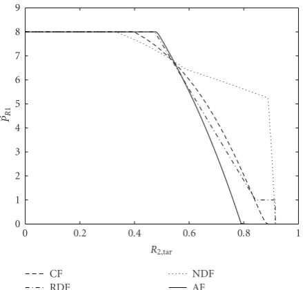
source-relay link and there is no benefit to allocate any relay power to node 2. For the same reason, the relay power allo-cated to node 2 in the case of NDF relaying is also zero. How-ever, in the case of NDF relaying, for small values ofr, there is no need to use all the relay power to relay the messages of node 1, that is,PR1<2PR, and it is sufficient to use only the amount of powerPR1that makes the arguments of the min function in (8) equal, that is,PR1=2P1(γ1R−γ10)r/(γR0(r+ 2P1γ10)). This can be seen in Figure 4 as the (steeply) decreasing dotted curve that represents the optimalPR1 for the case of NDF relaying. For values ofR2in this region, the average power that the relay needs to use is strictly less than its maximum average power. We also observe fromFigure 5
that the channel resource allocations for both RDF and NDF are the same. This situation arises because in both strategies the achievable rate of node 2 is limited by the achievable rate of the source-relay link. This rate has the same expression for both strategies, and hence, the same value ofrwill be allo-cated to node 2. A further observation fromFigure 3is that the achievable rate region for the CF relaying strategy is larger than that for AF and the achievable rate region for NDF is larger than that for RDF. This is consistent with the observa-tions in [13], where the comparisons were made in terms of the expressions in (2a), (2b), (2c), and (2d) withr=1/2.
1 0.5
0 R2
0.8 0.6 0.4 0.2 0
R1
0 0.1 0.2 0.3 0.4 0.5 0.6 0.7
R3
(a) RDF
1 0.5
0 R
2
0.8 0.7 0.6 0.5 0.4 0.3 0.2 0.1 0
R1
0 0.1 0.2 0.3 0.4 0.5 0.6 0.7
R3
(b) NDF
1 0.5 0
R2
0.7 0.6 0.5 0.4 0.3 0.2 0.1 0
R1
0 0.2 0.4 0.6 0.8 1 1.2 1.4
R3
(c) AF
1 0.5 0
R2
0.7 0.6 0.5 0.4 0.3 0.2 0.1 0
R1
0 0.2 0.4 0.6 0.8 1 1.2 1.4
R3
(d) CF
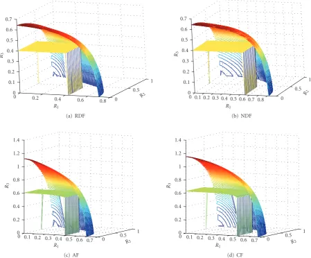
Figure11: The achievable rate regions obtained by jointly optimal power and resource allocation and those obtained by power allocation alone with equal resource allocation for three-user system with|K3R| =0.6,|K30| =0.9,P3=2, and the remaining parameters from Scenario
2 inTable 1.
plot inFigure 6the rate regions achieved by joint allocation and by power allocation alone for each relaying strategy. It is clear from the figure that the joint allocation results in significantly larger achievable rate regions. (The horizontal segments of the regions withr =0.5 inFigure 6arise from the allocation of all the relay power to node 1. In these cases, R2,tarcan be achieved without the assistance of the relay, and hence all the relay power can be allocated to the message of node 1.) As expected, each of the curves forr = 0.5 in Figure 6 touches the corresponding curve for the jointly optimal power and channel resource allocation at one point. This point corresponds to the point at which the value r=0.5 is (jointly) optimal.
In Figures 7–10, we examine the performance of the considered scheme in Scenario 2 of Table 1, in which the effective gain of the source-relay channel for node 2 is larger than that in Scenario 1, and that of the source-destination channel is smaller. As can be seen fromFigure 7, increasing the gain of the source-relay channel of node 2 expands the achievable rate of the RDF and NDF strategies, even though
the gain of the direct channel is reduced, whereas that change in the channel gains has resulted in the shrinkage of the achievable rate region for the CF and AF strategies. Therefore, we can see that the RDF and NDF strategies are more dependent on the quality of the source-relay channel than that of the source-destination channel (so long as the first term in the argument of the min function in (2a) and (2b) is no more than the second term), while the reverse applies to the CF and AF strategies. Figures8 and9show the allocations of the relay power and the channel resource parameter, respectively. It is interesting to note that for the RDF strategy, whenR2,taris greater than a certain value, the relay power allocated to node 2 will be constant. The value of this constant is that which makes the two terms inside the min function on the left-hand side of the first constraint of (6) equal. This value can be calculated from the expression
1.4 1.2 1 0.8 0.6 0.4 0.2 0
R2
0 0.1 0.2 0.3 0.4 0.5 0.6 0.7 0.8 0.9
R1
CF RDF NDF
AF NDF/CF CF/NDF
Figure12: Comparison between the achievable rate regions when using the same relaying strategy for both users and when using different relaying strategies, for Scenario 1.
Figure 6, it is again clear that the joint allocation results in significantly larger achievable rate regions. (The horizontal segments inFigure 10arise from all the relay power being allocated to node 1, because the corresponding values of R2,tarcan be achieved without the assistance of the relay.)
In Figure 11, we extend this comparison to a three-user case. In order to obtain the jointly optimal power and channel resource allocations used to plot this figure, we used a two-dimensional quasiconvex search algorithm analogous to that inAlgorithm 1to solve instances of the optimization problem in (13). As in the two-user case, a substantially larger rate region can be achieved by joint allocation of the power and the channel resource. It is worth mentioning that theR3 =0 slice through the jointly optimized region is the same as that obtained in the corresponding two-user case (cf. Figure 7). This is because whenR3,tar = 0, no power and none of the channel resource will be allocated to the message of node 3. On the other hand, the R3 = 0 slice through the region with fixed (and equal) resource allocation will be smaller than the corresponding region inFigure 7, because equal resource allocation in the three-user case corresponds tori=1/3. This indicates that as the number of source nodes increases, so do the benefits of joint power and resource allocation.
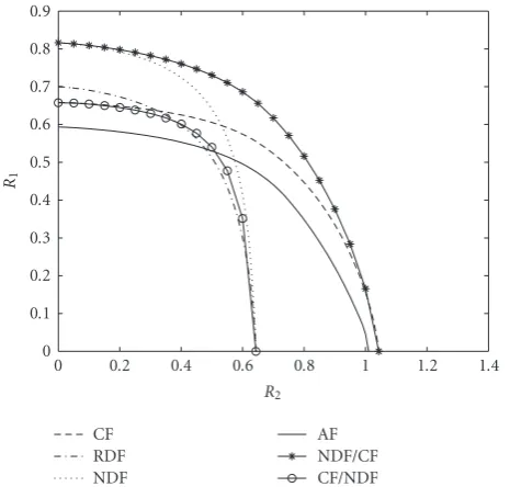
In the above examples, we have considered the case in which the relay applies the same strategy to the messages of all source nodes. However, in Figures12and13, we show that assigning different relaying strategies to the messages from different nodes may result in larger achievable rate regions. Figure 12shows that in Scenario 1, if the messages of node 1 are relayed with the NDF strategy and the messages of node 2 are relayed with the CF startegy, the resulting achievable rate region will be larger than that of the homogeneous NDF and
1 0.8
0.6 0.4
0.2 0
R2
0 0.1 0.2 0.3 0.4 0.5 0.6 0.7 0.8 0.9
R1
CF RDF NDF
AF NDF/CF CF/NDF
Figure13: Comparison between the achievable rate regions when using the same relaying strategy for both users and when using different relaying strategies, for Scenario 2.
CF strategies. If the relaying strategies are reversed, it can be seen that the achievable rate region will be smaller than that of both the homogeneous NDF and CF strategies. Since the NDF achievable rate region dominates the CF achievable rate region in Scenario 2 (seeFigure 7), it can be seen inFigure 13 that both combinations NDF/CF and CF/NDF provide smaller achievable rate regions than the pure NDF region. Therefore, in Scenario 2 NDF relaying for both source nodes provides the largest achievable rate region. The examples in Figures 12 and 13 suggest that one ought to jointly optimize the power allocation, the resource allocation, and the relaying strategy assigned for each node. Indeed, Figures 12and13suggest that significant gains can be made by doing so. However, the direct formulation of that problem requires the joint allocation of power and the channel resource for each combination of relaying strategies, and hence the computational cost is exponential in the number of source nodes. Furthermore, as the achievable rate region of the overall system is the convex hull of the regions obtained by each combination of relaying strategies, time sharing between different combinations of relaying strategies may be required in order to maximize the achievable rate region. The approach in [18] to the design of relay networks based on orthogonal frequency division multiplexing (OFDM) offers some insight that may lead to more efficient algorithms for joint power, channel resource, and strategy allocation, but the development of such algorithms lies beyond our current scope.
5. CONCLUSION
an orthogonal multiple access relay channel is quasiconvex, and hence simple efficient algorithms can be used to obtain the optimal solution. In addition, we obtained a closed-form expression for the optimal power allocation for a given resource allocation, and we used this expression to significantly reduce the complexity of the algorithm. The numerical results obtained using the proposed algorithm show that significant rate gains can be obtained over those schemes that apply only power allocation and equal channel resource allocation. Finally, we provided an example of the joint allocation of the power, the channel resource, and the relaying strategy, and showed that this has the potential to further enlarge the achievable rate region.
APPENDICES
A. PROOF OF PROPOSITION1
Assume that the solutions to (6) with r = rα andr = rβ are both greater than certain target rateC1,tar. Letxαandxβ denote the corresponding optimal values ofPR1. Then, we have that r 2min log
1+2γ1RP1 r
, log
1+2γ10P1+γR0PR1 r
≥C1,tar,
r 2min log
1+γ2rP2
r
, log
1+2γ20P2+γR0PR2
r
≥C2,tar, (A.1)
for (r=rα,PR1=xα) and (r=rβ,PR1=xβ). The inequalities in (A.1) can be written as
f1 xα
≥g1 rα
, f1 xβ
≥g1 rβ
, f2 xα
≥g2 rα
, f2 xβ
≥g2 rβ
, (A.2)
where
f1(x)=min2γ1RP1, 2γ10P1+γR0x
,
g1(r)=r 2 2C1,tar/r−
1,
f2(x)=min2γ2rP2, 2γ20P2+γR0(2PR−x)
,
g2(r)=r2 2C2,tar/r−
1.
(A.3)
Examining these functions, we observe that f1(x) and f2(x) are both concave functions. By differentiating g1(r) twice with respect torwe obtain
d2g1(r) dr2 =
4C2
1,tarln (2)222C1,tar/r
r3 ≥0, (A.4) and hence,g1(r) is a convex function inr. Similarly, we can show thatg2(r) is convex inr.
Now, if we considerrγ =μrα+μrβ andxγ =μxα+μx β, whereμ∈[0, 1] andμ=1−μ, then
f1 xγ
≥aμ f1 xα
+μ f 1 xβ
≥μg1 rα
+μg 1 rβ
≥bg1 rγ
,
(A.5)
wherea follows from the concavity of f1(x) and b follows from the convexity ofg1(r). Similarly, it can be shown that
f2 xγ
≥g2 rγ
. (A.6)
Hence, for any two values ofr (namely,rαandrβ), if there exist values ofx(namely,xαandxβ), such that the conditions in (A.1) are satisfied, then for any value ofrthat lies between rαandrβ (namely,rγ = μxα+μx β), there exists a value for xthat lies betweenxαandxβ(namely,xγ=μxα+μx β) such that the conditions in (A.1) are satisfied. Therefore, the set of values ofr for which the solution of the problem in (6) is greater than a certain target rateC1,taris a convex set. Hence, the problem in (6) is quasiconcave inr.
B. PROOF OF PROPOSITION2
We begin by showing that the function (r/2) log((1+a/r)(1+ bx/r)) is quasiconcave in the variablesrandx, whereaandb are nonnegative constants. To do so, we assume that the pairs (rα,xα) and (rβ,xβ) satisfy
r 2log
1 + a r
1 +bx r
≥M, (B.1)
whereMis a nonnegative constant. We can write (B.1) as f0(r,x)≥g0(r), (B.2) where
f0(r,x)=r+bx, g0(r)=r 222M/r
r+a . (B.3) The function f0(r,x) is a linear function, while the function g0(r) can be shown to be convex function using the fact that
d2g0(r) dr2
= 2a222a/r r2 1−ln(2)2+ 2arln(2) 2 ln(2)−1 + ln (2)2 r2+ 2a2× r+a3r2−1 ≥0.
(B.4)
Now,if we considerrγ=μrα+μrβandxγ=μxα+μx β, where μ∈[0, 1] andμ=1−μ, then
f0 rγ,xγ
=μ f0 rα,xα
+μ f 0 rβ,xβ
≥μg0 rα
+μg 0 rβ
≥ag0 rγ
,
(B.5)
whereafollows from the convexity ofg1(r). Therefore, the set of pairs (r,x) that satisfy (B.1) is a convex set, and hence the function (r/2) log((1 +a/r)(1 +bx/r)) is quasiconcave in the variablesrandx.
By obtaining its second derivative, it is straight forward to show that (r/2) log(1 + (2γ1RP1/r)) is concave inr. Since the minimum of a concave function and a quasiconcave function is a quasiconcave function, then we can say that the function
r 2min
log
1 +2γ1RP1 r
, log
1 +2γ10P1 r
+ log
1 +γR0PR1 r
is quasiconcave inrandPR1. Similarly, the function
r 2min
log
1 +2γ2rP2
r
, log
1 + 2γ20P2
r
+ log
1 +γR0 2PR−PR1
r
(B.7)
can be shown to be quasiconcave inrandPR1. Therefore, the problem in (8) is quasiconcave inrandPR1. That is, the set of all pairs (r,PR1) for which the solution of the problem in (8) is greater than a target rateC1,tar, that is, the set of all pairs that satisfy
r 2min
log
1 +2γ1RP1 r
, log
1 +2γ10P1 r
+ log
1 + γR0PR1 r
≥C1,tar,
r 2min
log
1 +2γ2rP2
r
, log
1 +2γ20P2
r
+ log
1 + γR0PR2
r
≥C2,tar,
(B.8)
is a convex set.
C. PROOF OF PROPOSITION3
Consider the function
f(r,x)=rlog
1 +a r +
bcx r(r+b+cx)
, (C.1)
wherea,b, andcare positive constants and (r,x)∈(0, 1)×
R++. We will avoid the cases where r = 0 or r = 1 because these cases correspond to scenarios in which one of the source nodes does not transmit. In those scenarios, the problem is easy to solve because all the relay power and all the channel resource will be allocated to the transmission of the message of the other source node. We will show that f(r,x) is quasiconvex using the the second-order condition for the quasiconvexity which states that [14] for any vectorzsuch thatzT∇f =0, if the function f satisfieszT∇2fz<0, then
f is quasiconcave.
For the function f, we denote the gradient by ∇f = [fr, fx]T, where fw =∂ f /∂w. Since∇f ∈R2, the subspace orthogonal to∇f will be a one-dimensional subspace. Since the vectorz=[−fx, fr]T is orthogonal to∇f, then all the vectors in the subspace orthogonal to∇f are parallel to the vectorz. Examining the quantityzT∇2fz, we have that
zT∇2fz= −Af(r,x) 2 r2 +B
f(r,x)
r −C, (C.2) whereA,B, andCare positive quantities that depend on the constantsa,b, andcand the variablesrandx. Equation (C.2) can be written as
zT∇2fz= −
√
Af(r,x)
r −
C
2
+ (2AC−B)f(r,x) r
.
(C.3)
From (C.3), it can be seen that it is sufficient that 2√AC > B for the quantityzT∇2fzto be negative and consequently for
the function f(r,x) to be quasiconcave in (r,x). Since both the quantities 2√ACandBare positive, we can examine the quantities 4ACandB2. In particular, it can be shown that
4AC−B2=4 5abcxr2−bcxr3
+ 3ab2r2−b2r3+abr 3−br4
+ 4ab3cx+ 10ab2cxr+ 2b3cxr+ 2a2c2x2r + 6a2b2r+ 6a2br2+ 2a2r3+ 2a2b3
+ 4bac2x2r+ 4ab2c2x2+b2r2cx+ 2a2bc2x2 + 4a2r2cx+ 8a2bcxr+ 4a2b2cx+ 2arb3 + 2b2c2x2r+ 2b3c2x2×r2b3c4(b+r)2 × rb+rcx+r2+ab+acx+ar+bcx−5 ×(b+cx+r)−4.
(C.4)
The underbraced terms in (C.4) contain the negative terms in (C.4), each paired with a corresponding positive term. It can be seen that ifa≥r, then each of these underbraced terms is nonnegative. Therefore,a≥1 is a sufficient condition for 4AC > B2, and hence is a sufficient condition for the function
f(r,x) to be quasiconcave.
By making the substitutionsa = 2γ10P1,b = 2γ1RP1, c = γR0, and x = PR1, the sufficient condition becomes 2γ10P1 ≥1, that is, if the maximum achievable SNR of the direct channel of node 1 is at least−3 dB, then the objective function in (9) is quasiconcave in (r,PR1). Similarly, we can obtain that 2γ20P2 ≥ 1 is a sufficient condition for the function on the left hand side of the first constraint in (9) to be quasiconcave in (r,PR2). Therefore, the problem in (9) is quasiconcave in (r,PR1) if the maximum achievable SNR of the direct channel of both nodes is at least−3 dB.
D. PROOF OF PROPOSITION4
Following a similar proof to that inAppendix C, consider the function
f(r,x)=rlog
1 +a r +
bc(a+r)x
r(r2+ (a+b)r+c(a+r)x)
,
(D.1)
wherea,b, andcare positive constants and (r,x)∈(0, 1)×
R++. Define zto be the vector orthogonal to the gradient subspace of the function f(r,x), that is, z = [−fx, fr]T. Examining the quantityzT∇2fz, we have that
zT∇2fz= −A r2f(r,x)
2+B
r f(r,x)−C,
= −
√
Af(r,x)
r −
C
2
+ (2AC−B)f(r,x) r
,
(D.2)
where of courseA,B, andC are different positive functions ofa,b,c,r, andxthan those inAppendix C.
the function f(r,x) to be quasiconcave in (r,x). Since both 2√ACandBare positive, we can examine
4AC−B2
=4b3c4r5 20ba3r4−3bar6
+ 18 b2a3r3−2b2ar5
+ 20bcxa2r4−bcxr6
+ 8b2a2r4−b2r6
+ 7ba5r2−br7+12a2r2b2c2x2+ 2r5cxb2 + 2r4c2x2b2+ 4ar4bc2x2+ 2a2r4c2x2 + 2r4cxb3+ 10ar4b2cx+ 2a2r6 + 24a2r3b2cx+ 8ar3b2c2x2+ 11a5bcxr + 10a4xcrb2+ 8a5r3+ 2a6r2
+ 16a2r3bc2x2+ 3a3xcrb3+ 37a4r2cxb + 16a4x2c2rb+ 9b2r2a4+ 5a2xcr2b3 + 2a6x2c2+a2r2b4+ 8a3x2c2rb2 + 26a3b2cxr2+ 4a2br5+ 4a2r5cx + 24a3br2c2x2+ 44a3br3cx+ 8x2c2a3r3 + 12a4r2c2x2+ 24a4r3cx+ 5b3r3a2 +ar5bcx+ 16a3r4cx+ 12a4r4 + 4ar3b3cx+ 8a3r5+ 2a4x2c2b2 + 4a6rcx+ 8a5c2x2r+ 4a5x2c2b + 16a5r2cx+ 5b3r2a3+ 21a4r3b × 2ar+r2+a2+ab+rb−2(cx+r)−4 × acx+rcx+ar+rb+r2−5.
(D.3)
The underbraced terms of (D.3) contain the negative terms in (D.3), each paired with a corresponding positive term. It can be seen that ifa ≥ r, each of these underbraced terms is nonnegative. Therefore, a ≥ 1 is a sufficient condition for 4AC > B2, and hence for the function f(r,x) to be quasiconcave.
Making the substitutions a = 2γ10P1, b = 2γ1RP1, c = γR0, and x = PR1, the sufficient condition becomes 2γ10P1 ≥1. That is, if the maximum achievable SNR of the direct channel of node 1 is at least−3 dB, then the objective function in (11) is quasiconcave in (r,PR1). Similarly, we can obtain that 2γ20P2 ≥ 1 is a sufficient condition for the function on the left hand side of the first constraint in (11) to be quasiconcave in (r,PR2). Therefore, the problem in (11) is quasiconcave in (r,PR1) if the maximum achievable SNR of the direct channel of both nodes is at least−3 dB.
ACKNOWLEDGMENTS
This work was supported in part by a Premier’s Research Excellence Award from the Government of Ontario. The work of the second author is also supported in part by the Canada Research Chairs program. A preliminary version of part of this work appears in the Proceedings of the 2008 International Symposium on Information Theory.
REFERENCES
[1] G. Kramer, M. Gastpar, and P. Gupta, “Cooperative strategies and capacity theorems for relay networks,”IEEE Transactions on Information Theory, vol. 51, no. 9, pp. 3037–3063, 2005. [2] G. Kramer and A. J. van Wijngaarden, “On the white Gaussian
multiple-access relay channel,” in Proceedings of the IEEE International Symposium on Information Theory (ISIT ’00), p. 40, Sorrento, Italy, June 2000.
[3] L. Sankaranarayanan, G. Kramer, and N. B. Mandayam, “Capacity theorems for the multiple-access relay channels,” in Proceedings of the 42nd Annual Allerton Conference on Communication, Control and Computing, Monticello, Ill, USA, September-October 2004.
[4] L. Sankaranarayanan, G. Kramer, and N. B. Mandayam, “Cooperation vs. hierarchy: an information-theoretic com-parison,” inProceedings of the IEEE International Symposium on Information Theory (ISIT ’05), pp. 411–415, Adelaide, Australia, September 2005.
[5] T. M. Cover and J. A. Thomas,Elements of Information Theory, John Wiley & Sons, New York, NY, USA, 1991.
[6] A. Sendonaris, E. Erkip, and B. Aazhang, “User cooperation diversity—part I: system description,”IEEE Transactions on Communications, vol. 51, no. 11, pp. 1927–1938, 2003. [7] A. Sendonaris, E. Erkip, and B. Aazhang, “User cooperation
diversity—part II: implementation aspects and performance analysis,”IEEE Transactions on Communications, vol. 51, no. 11, pp. 1939–1948, 2003.
[8] J. N. Laneman, D. N. C. Tse, and G. W. Wornell, “Cooperative diversity in wireless networks: efficient protocols and outage behavior,”IEEE Transactions on Information Theory, vol. 50, no. 12, pp. 3062–3080, 2004.
[9] L. Sankaranarayanan, G. Kramer, and N. B. Mandayam, “Hierarchical sensor networks: capacity bounds and coop-erative strategies using the multiple-access relay channel model,” inProceedings of the 1st Annual IEEE Communications Society Conference on Sensor and Ad Hoc Communications and Networks (SECON ’04), pp. 191–199, Santa Clara, Calif, USA, October 2004.
[10] K. Seddik, A. K. Sadek, W. Su, and K. J. R. Liu, “Outage analysis and optimal power allocation for multinode relay networks,”
IEEE Signal Processing Letters, vol. 14, no. 6, pp. 377–380, 2007. [11] T. M. Cover and A. El Gamal, “Capacity theorems for the relay channel,”IEEE Transactions on Information Theory, vol. 25, no. 5, pp. 572–584, 1979.
[12] L. Lai, K. Liu, and H. El Gamal, “The three-node wireless network: achievable rates and cooperation strategies,” IEEE Transactions on Information Theory, vol. 52, no. 3, pp. 805– 828, 2006.
[13] S. Serbetli and A. Yener, “Relay assisted F/TDMA ad hoc networks: Node classification, power allocation and relaying strategies,”IEEE Transactions on Communications, vol. 56, no. 6, pp. 937–947, 2008.
[14] S. Boyd and L. Vandenberghe, Convex Optimization, Cam-bridge University Press, CamCam-bridge, UK, 2004.
[16] Y. Liang and V. V. Veeravalli, “Gaussian orthogonal relay channels: optimal resource allocation and capacity,” IEEE Transactions on Information Theory, vol. 51, no. 9, pp. 3284– 3289, 2005.
[17] A. Wyner and J. Ziv, “The rate-distortion function for source coding with side information at the decoder,” IEEE Transactions on Information Theory, vol. 22, no. 1, pp. 1–10, 1976.
[18] T. C.-Y. Ng and W. Yu, “Joint optimization of relay strategies and resource allocations in cooperative cellular networks,”