COURSE
001
INTRODUCTION TO COMPUTERS
SECTION 1
Components of ~ Computer
CRAPI'ER 1
INTRODUCTION
TO THE UNIVAC
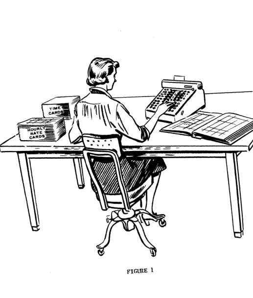
The Univac is an electronic computer designed to perform repetitive clerical and mathematical computations at a high rate of speed and accuracy. In order to'make clear the function of each component of the computer and their interrelations let us consider the operation of a payroll clerk.
The clerk has a stack of time cards listing the hours worked by each employee of the company. She has a second stack of cards that contains the hourly rate of pay, number of dependents, and other fundamental information about each of the employ-ees.
To aid her in her work she has a desk calculator which enables her to do addition, subtraction, multiplication and division. A ledger book is also provided for entering the desired pay data as it is computed.
In addition to the above elements, the clerk provides a supervisory element: She selects a time card and hourly rate card for each employee and by means of the calculator multiplies hours by rate to obtain a gross pay, subtracts from this his witholding tax, etc., and enters the net paw in her ledger.
This payroll process can be thought of as requiring four elements: input, output, arithmetic, and supervision. As shown in Figure 1, the time cards and hourly rate cards are the input, the calculator accomplishes the arithmetic, the ledger entries are the output, and the clerk is the supervision.
When we examine further the role of the clerk in this operation, we find that her ability to turn the input of time and rate cards into the ledger entries of net pay depends upon her remembering the individual steps of the operation, her in-structions and the order of their execution. That is, she must remember that she is tv subtract the witholding tax from the gross pay, and that this tax is com-puted by multiplying the number of dependents by $13.00 and subtracting this from tpe gross pay, multiplying the difference 'by 20%, and so forth. Her supervision then actually consists of two functions, memory and control. This memory function becomes even more evident if the clerk has other duties to perform as well. She may be required to maintain the rate cards: for example, changing a man's rate of
pay when he is given a raise or adding or removing dependents upon notice.
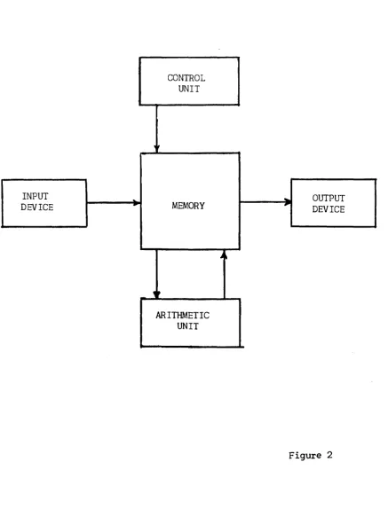
The Univac is such a General Purpose Computer. Its five components and their In-terrelations are shown in Figure 2. The memory occupies a central position. It holds for processing the data coming from the input unit. It also holds the in-structions that tell what to do with this data. The control unit selects each instruction from the memory in proper sequence and executes it. Instructions might call for the hourly rate and total hours worked to be extracted from the memory and delivered to the arithmetic unit for multiplication, the product being returned to the memory. As the net wages are computed, they are sent to the out-put unit for permanent recording.
In order to secure high operating speeds, these units are of electronic construc-tion; and to assure complete accuracy, many of the units are duplicated and cross-checked. Other checking means are used when it is not feasible to duplicate equip-ment.
There is yet another way in which computers may be categorized which is intimate-ly related to the concept of memory •. The basic element being processed by a com-puter is a number. We are all familiar wit~ two ways of representing numbers:
1. The digital method, possibly the oldest, uses a unique symbol or mark to represent each number. For example, we use the Arabic symbols with the position concept when we say that a dozen is "12" and a dozen dozen or gross is
"144". .
2. The analog method is familiar to us in the slide rule where numbers are represented by different distances along a stick, or by an-ammeter which represents the number of amperes of current flow by the angle of a pointer. Other commonly used representations are voltage levels, ro-tation of a gear of shaft, and extension of a spring.
Computers may then be of two general types: Special Purpose or General Purpose, depending on whether they have a stored program of alterable instructions or not. Within each type a computer may be Digital or Analog depending upon the
represent-ation of numbers. .
CONTROL UNIT
d,
INPUT --"-
...
OUTPUTDEVICE MEMORY
,.
DEVICEA"
,~
SECTION 11
The Memory Unit
In order to understand the operation of the Univac, we will start with the central unit of the five units: The memory. The physical make-up of the memory will be discussed in Chapter
8,
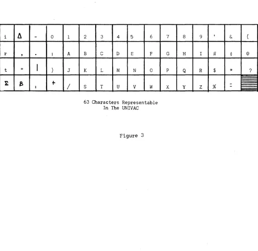
however, we will now describe the general characteristics which concern the user of a computer.The basic unit of memory in the Univac is the "word". A word always consists of twelve characters or digits. There 63 possible characters available; any combinatlon of twelve of these constitutes a word. The 63 characters available are shown in Figure~
but for our immediate needs we need only the numbers 0, 1, 2, ••• 9 and the letters of the alphabet A,B,C, ••• Z and the dash symbol (-). Here are some typical words:
012345678906 -00121169876 ABCDEFG986HJ JOHNNY-JONES
For ease of reference the digit positions of a word are numbered from left to right. Thus, in the last example above, the character in digital position 7 is the dash.
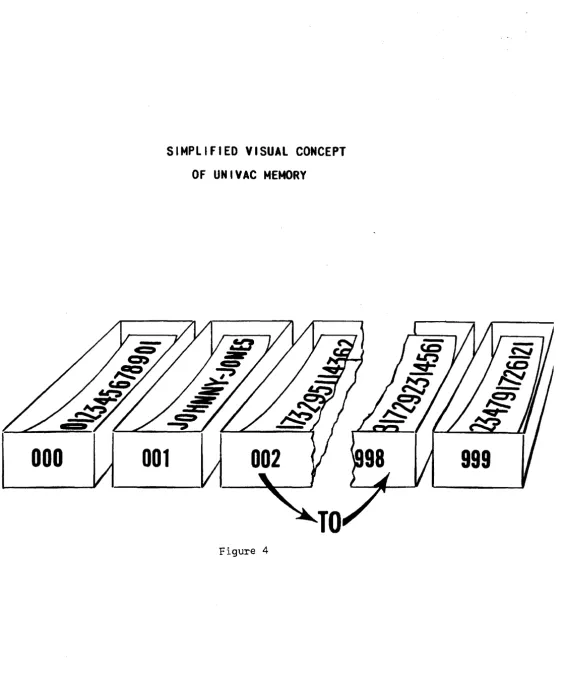
The memory of the Univac has the capacity to "store" or "remember" 1000 such words. The memory may be visualized by picturing 1000 boxes, and in each box is a slip of paper with a Univac word written on it (figure 4). In order to locate a part-icular word we number or "address" the boxes. In Univac the boxes are numbered c0nsecutively from 000 to 999. Thus, in Figure 4, we can speak of the word in box 001 as being JOHNNY-JONES.
When ~ word represents ~ number, the character in digit position 1 is considered as the sign of the number. The minus sign is the dash symbol while the plus sign is a zero.
-61321542013 061321542013
Further, the computer considers all numbers to be less than one in magnitude. That is, it assumes a decimal point between digit positions 1 and 2.
A later chapter will describe how numbers larger than one can be represented.
As mentioned in Section 1, a General Purpose Computer stores its instructions in a memory. In the Univac these instructions are stored in the same 1000 word
memory as the data they are to operate upon. A Univac instruction consists of six digits designated from left to right as "first instruction digit", "second
struction digit" ••• "sixth instruction digit". The fourth, fifth, and sixth in-struction digits generally are the address of some memory box, and the first and second instruction digits indicate what operation is to be done on the word at that address. The instructions will be described in Chapter 2.
Since an instruction is six digits long, a Univac word can contain two instructions. Thus, when ~ word represents instructions, The left six digits (digital positions
i
II
-
0 1r
,
.
; At "
I
) J11
e
+
/
:
2 3 4 5 6
B C D E F
K L M N 0
S T U V W
63 Characters Representable In The UNIVAC
Figure 3
7 8 9 1
&. (
G H I # ¢ @
p Q R $
*
?-000
SIMPLIFIED VISUAL CONCEPT
OF UNIVAC
MEMORY
001
Figure 4
SECTICN I I I
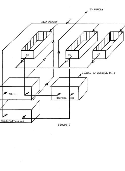
The Arithmetic Unit
The arithmetic unit consists of an algebraic adder, a multiplier-divider, a com-parator, and several special memory boxes called registers:
Register A, rA, which holds one word
ff
L, rL,
ff ff ff "" F, r F , " " ff "
TO MEMORY
SIGNAL TO CONTROL UNIT
ADDER
COMPARA
SECTION IV
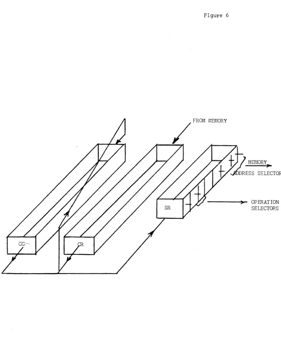
The Control Unit
The control unit selects the instructions placed in the memory and executes them in their proper order. The control unit cons~sts of synchronizing and effector devices and three registers:
The Control Counter, CC, which holds ~ne word The Control Register, CR, which holds one word The Static Register, SR, which holds one-half word
Figure 6 depicts the interconnections between these registers. The word in the Control Counter always has the following appearance:
oooooooooxxx
where XXX is some number between 000 and
999.
This number is the address of the next pair of instructions to be executed. A computer which stores its instruc-tions in a memory must first locate and extract from this memory the instruction and then execute it. Since the UNIVAC stores two instructions per word, each memory look-up selects a pair of instructions. The Control Register is used to hold one instruction while the other is being executed. In Univac the extraction and execution of instructions is performed in four steps which are identified by the first four letters of the Greek alphabet:C1
y
Description
The right hand six digits of CC are duplicated in SR. The memory address section of SR now contains the address of the next instruction pair.
The effector circuits of SR now cause the contents of the memory cell as specified by the address section of SR to be duplicated in CR.
A one is added in the least significant digit posi-tion of CC (digit posiposi-tion 12).
The Left Hand Instruction now in CR is duplicated in SR, and being in SR causes the effector circuits to execute it: that is, interpret it as an instruc-tion.
Figure 6
SECTION V
Input and Output Units
C0mmercial calculati0ns almost always involve vast amounts of data, volumes far in excess of the storage capacity of the main memory of any computer. In the Univac System, volume storage of data is achieved through magnetic recording on metallic tape. Initial transcription of data onto magnetic tape is achieved through terminal equipment (Unitypers, Card-To-Tape Converters) to be described later. The input of the Univac consists of a number of magnetic tape units called Uniservos which will read the information recorded on tape into an input register, rI, where it may then be transferred into the memory. These same Uniservos will also record information on metallic tape and serve as output units. Uniprinters, Tape-Tc-enu Converters, and High-Speed Printers serve as terminal equipment on the output end. These devices, also to be described later, read magnetic tape and produce a visible or hard copy of the information. Data in the memory is first transferred to an output register, rO, from which the Uniservos operate. Thus, only small amounts of data need be brought into the main memory at one time for processing. After calculation, the results are re-corded on tape and the original data replaced by new data tape.
Figure 7 shows the interconnections b$tween memory, input, and output units.
INPUT REGISTER
READING CIRCUITS
MEMORY
0000
•
UNISERVOS
OUTPUT REGISTER
•
•
00
.,;j!
~'
SECTION 1
Introduction and Notation
CHAPTER 2
PROGRAMMING
The Univac System responds to 43 basic instructions which are summarized in the Appendix of the Univac Programming Manual. These instructions were selected after a detailed study of many data processing problems to determine the most desirable and efficient set. The complete code with the unique characteristics of many of the instructions provides the skilled coder a highly efficient and flexible means of problem solution.
Our purpose in this course, however, is solely the development of your comprehen-sion of computers - as to what problems can be solved on them and a general under-standing of how the solution is prepared. For this reason, we shall consider a restricted set of instructions. For many of these instructions we shall describe only their main characteristics for the sake of simplicity. As each group of in-structions are described, sample problems will be coded to illustrate their use. Further problems are included as student exercises; solutions of these problems will be found in the Appendix.
Chapter 1 described the Univac instruction as consisting of 6 digits. The digits were labeled as shown in the figure below:
x
X X X X XL
6th InstructionMew..o"''1 5th Instruction (c. \ \
Adl~cs.So
4th Instruction
3rd Instruction
Digi]
1
~I)t V'u(.t \ . "2nd Instruction Digit \
1st Instruction Digit
SECTION 11
Instruction List
A
B¢tm,
This instruction, when executed by the computer, causes the word in memorycell m to be duplicated in rAe The former contents of rA are erased. The word will still remain in m, unaltered. This is true of all instructions reading
information from the memory or the special registers.
H~¢ m, This instruction, when executed by the computer, causes the word in rA to be duplicated in memory cell m. rA remains unaltered, but the former contents of m are, of course, erased.
~, This instruction, when executed by the computer, causes the word in m and the word in rA to be sent to the adder, the sum being stored in rAe The initial contents of rA will be destroyed, but the contents of m will remain unaltered.
siC
m, This instruction is similar to the add instruction above, except the con-tents of m are subtracted from rAe~,~4ThiS
instruction causes the computer to print on the Supervisory Control Printer the word contained in cell m. The contents of m are not altered.~ 1...,~t'R.\)('T'O~ WI\\ WR.lte. 0\1 lA-PE. \~O ~uh.e:s /(t.JCt1.
~, This instruction causes the computer to stop executing .instructions. Mem-ory address m is ignored. "¢: 5.ToP
It is desirable at this point to code a simple problem to illustrate these in-structions:
Memory location 100 contains the on hand amount of a certain stock item. Memory location 101 contains the on order amount, while cell 102 gives the expected requirements for the next sixty days. Compute (on hand)+
(on order) - (required), print and stop.
It is convenient to start the instructions in cell 000, though any other location (except 100-102) will do. In this case the solution is:
Memory Cell
001
Contents
Left Inst. Right Inst.
B¢Q 100
sod
102500 103
A00 ldl
HOO ld3
900 (/;(/)0
Remarks
on hand-+-rA
rA + on order-+- rA rA - required-.-rA Store rA for printing Print
stop
In the B, H, A, and S instructions we needn't specify the second instruction digit and would write them as B 100 for example. This is solely to save effort
in writing the instructions, these omitted digits will be inserted by the oper-ator when the instructions are placed in the memory.
Student Exercises
1. Memory locations 100-104 contain a list of receipts; print their total and stop.
2. The following quantities are stored in the designated locations:
l~d: A
l¢l: B
1~2: C 103: D
SECTION III
Instruction List
A,
Continued~ This instruction duplicates in rL, the contents of memory cell m.
M
m, This is the multiply instruction. The words in.m and rL are sent to the multiplier and the rounded product is stored in rAe The former contents of rA are destroyed.D
m, This instruction sends the contents of m and rL to the divider, the rounded quotient, (m)f
(rL), is stored in rAe The former contents of rA are destroyed.You will recall, in Chapter 1, we noted that Univac considers the decimal point to lie between digit positions 1 and 2, and that digit position 1 is the sign digit. This means that as far as the computer is concerned, every number lies between 1 and -1. How then, can we represent numbers larger than one?
No problem is involved when addition or sUbtraction are the only arithmetical operations involved, as we may assume a decimal point at any desired position in the word. For example, if we let the inverted carat/\ indicate the assumed decimal point, the assumed decimal point of a sum or difference will be in the same position as for its factors:
$3600.05
036
oaR
500
000 000 000 360W
5 156.23 0015~
300 000 000 000 015W
3$3756.2S 037 5~
sao
000 000000 375
~8But for multiplication:
$15.32 x 2.5
=
$38.30Ol~ 320 000 000 x 00~500 000 000
=
000 38K
000 000The assumed point is not in the same position for the product as for the factors. A similar result is also true for division. A simple set of rules tells us where the assumed decimal point of a product or quotient lies when the assumed decimal point of its factors are known.
Rules for Positioning Decimal Points
Rule for Multiplication: If the assumed decimal point lies m places to the right of the machine decimal point in one factor and n places to the right in the other, the assumed decimal point of their product will be m + n places to the right of its machine decimal point.
Rule For Division: If the assumed decimal point of the dividend lies m places to the right of the machine point while that of the divisor lies n places right, the assumed point of the quotient lies m-n places to the right of the machine point. Here again negative m, n, or m-n are interpreted as meaning the assumed point lies that number of places left of the machine point.
A
=
!xx
XXx
XXX XXX1\
B -
!:X"
X XXX XXX XXXA x B
=
±XX
XXX"XXX XXXA t B
=
!xx
XAXX XXX XXX Student Exercises:EXAMPLES
A
=
~ XXX XXX XAXXB ,,~ XXX XXX XXX
A x B
=±xx
XXX XXXI\ XXXA + B
=
±Xx
XXXXXX XX"XIndicate Position of Assumed Decimal Point
1. A
=
!"
XX XXX XXX XXX B=
!"xx
XXX XXX XXX 2. A=
~XX XXX XXX X"XX B=
tl\XX XXX XXX XXX3. A =
txx
XXX XX"X XXX B=
"tXX X" XX XXX XXXA x B =?
A ~ B =?
A x B =?
SECTION IV
Instruction List ~
¢O
m, This is the skip instruction. It tells the computer to pass on to the next instruction altering neither the memory or registers.U m, This instruction is often called an unconditional transfer of control. As mentioned in Chapter 1, this is one of the instructions that break the sequential execution of instructions. The U m instruction tells the computer to begin exe-cuting instructions sequentially beginning with the instruction pair in cell m. The memory and arithmetic registers are not affected.
In detail, the U m instruction causes the memory address digits of the Control Counter to be replaced by the address m. The U m instruction must be a Right Hand Instruction to be executed as described. This is true only of the U, Q,
and T instructions (see below). All other instructions work equally well as Left or Right Hand Instructions.
~, This is one of two conditional transfer of control instructions. The U m instruction always transfers control, but the Q m instruction transfers control only upon certain conditions. If the contents of rA and rL are identical, the computer interprets the Q m instruction as though it were a U m. If rA is not equal to rL, the Q m is interpreted as a skip. This instruction then allows a choice between following one set of instructions rather than another when that choice can be expressed by the equality of two numbers (or alpha-numbers).
T m, This is the other conditional transfer of control instruction. This in-struction acts similarly to the Q m instruction, e',=cept that the condition for transfer is now that rA be algebraically larger than rL. A few examples will illustrate the principle.
rA
012 345 678 910 -12 345 678 910 012 345 678 910 -12 345 678 910
rL
009 761 835 011 009 761 835 011 -99 999 999 999 -99 999 999 999
Does T m Transfer Control?
Yes No Yes Yes
rA
ABC DEF GHJ KIM
III III III AZ9
-AB 904 6DE FG7 -AB 904 6DE FG7
Example Problem #1
rL
123 456 789 ABC
III III III BZZ
000 123 456 789 -12 345 678 9AB
FICA CALCULATION
Does T m Transfer Control
Yes No No No
A year-to-date total of FICA taxable earnings, FE, is stored in memory cell 100. A year-to-date FICA tax paid, FT, is stored in cell 101. This week1s pay, P, is
stored in cell 102. Compute the FICA tax, T, for this week and print, bringing the totals up~to-date. Assume that the assumed decimal points are FE
=
OXX XXX XXX 1tX, FT=
OXX XXX XXX ~X, P=
OXX XXX XXX ~.Memory Cell
Contents
Left Inst. Right Inst.
000 001 002 003 004 005 006 007 008 009 010 all 012 B 00 B L H S B H A 50 M B 00 100 000 014 102 099 101 100 100 098 098 016 102 000
L
014Q 013
S 2-,JJ T 010 B 015
H 098
A 099 ]
B H 90 H H 101 101 000 098 099
J
RemarksTransfer Control if FE = $3600
Transfer Control if $3600-FE:> P
$3600-FE~ Storage
$72-FT ~ Storage
Sum year-to-date FICA earnings
Sum year-to-date FICA Tax
Print Tax Stop
• 02 X P ~Storage
Example Problem #2:
MEDICAL PAY CALCULATION
Memory Cell 100 contains the number of days medical absence, MA, an employee re-ported. In memory cell 101 is stored his hourly rate of pay, R, while in cell 102 is the number of days remaining of his payable medical absence allowance, M1. Calculate the medical pay, MP, and print, reducing the medical leave allot-ment by the amount MA.
Assume that the assumed decimal points are:
MA:
oxx"
000 000 000M1:
IxXA
000 000 000R:
oxx X"xx
000 000 MP:OXX XXX XXX XAXX
Memory Contents
Cell 1eft Inst. Right Inst Remarks
000 B 100
L 013
001 00 000
~ 012 Transfer Control if MA
=
a
002 B 102
T 006 Transfer Control if M1>
a
003 50 013 Print Zero00 000 004 B 102
]
S 100 ML-MA ~ M1 005 H 102
90 000 Stop 006 1 100
T 008 Transfer Control if ML >MA
007 1 102
00 000
}
008 M 014
H 099 8.r1 • R~Storage
009 1 099
M 101 010 H 099
50 099 Print MP all 00 000
u
004012 50 013 Pri,nt Zero 90 000 Stop
013 000 000
000 000 . 014 000 080
Student Exercises:
1. Three numbers A, B, and C are stored in memory locations 100, 101, and 102 respectively. Print the smallest and stop.
2. The following data pertaining to an employee is stored in the indi-cated memory cells:
100: Employee's badge number, BN. 101: Weekly bond deduction, BD.
102: Size of bond to be purchased, BS. 103: Employee's bond account number, BA. 104: Cumulative bond deduction, BC.
SECTION I
Introduction
CHAPTER 3
FLOW CHARTS
From a logical standpoint Univac instructions (and those of most digital com-puters) can be grouped into three categories which we might call "logical oper-ations":
A) Transfer of information from one storage location or medium to another. Typical of the instructions in this category are B m, H m, and L m.
B) Arithmetic manipulation of information, as typified by the instructions
A m, M m, D m.
c) Decision as to following course A or Course B, based upon the relative magnitudes of numbers. Instructions in this category are the T m, Q m, and redundantly, U m.
"Programming" may then be defined as the act of combining these three logical operations to "solve" a given problem, and a "program" is the resulting combina-tion. "Coding" is the act of translating the program into the instruction code of a particular computer and is sometimes used to designate the completed trans-lation as well.
When used in this sense, programming is the most involved step in preparing a problem for a computer solution. Coding the program is very nearly a mechanical process and in several cases computers have been successfully instructed to do their own coding. Construction of the program is the most difficult step for beginning students of digital computer techniques because it often requires visualizing large parts, if not all, of the problem as a unit. To some extent a program will reflect characteristics of the computer at hand. For example, a problem programmed for computer X having six input-output units wili differ from the program for computer Y with only three, though often these differences are slight.
Assembling and Ordering Symbols:
SECTION 11
Flow Chart Symbols
The "path of computational flow" is indicated by a directed line segment:
>
The inference that the next step in the problem will be found by moving along the line in the direction of the arrow is obvious. Where two or more different paths of computational flow merge to follow one common path, a "fixed connector" is placed at the point of merging:
If for reason of clarity we wish to indicate that a certain conditi'Jn is true at a certain point in the line of computational flow, a "flag" asserting the condition is attached to the flow line:
A B
Logical Decision Symbols:
A decision between follovling one of two paths of computational fl'Jw, based up·Jn the relative magnitudes of two quantities A and B is indicated by:
A
>
BA B
A c::: B
Or, for the choice of paths based upon the equality of the two quantities:
A
=
BA B
Standard practice has been to dispense with the flags in the case of a decision operation by the following scheme:
>
Ambiguity is avoided if we remember that the condition existing on either out-ward flow line is that obtained by replacing the colon (:) with the> or ~ symbol where the choice is made on relative magnitude or by
=
or ~ when the choice is based upon equality.Arithmetic and Transfer Symbols:
The evaluation of a formula or straight computation is indicated inside a rec-tangular box
.02A ~ B
Where the arrow indicates that B is now the quantity .02A, a transfer would appear as
A - . B II
SECTION III
Example Flow Charts
Let us illustrate the use of these flow chart symbols by drawing the flow charts for the FICA
and
medical pay calculation problems of Chapter 2.I
FICA CALCULATION
No TAX
r: .... _~ 3600-FE ~ WS
P .--.. WS .02P
0 - 4 F E + WSi ----+ FE
H ...
T_+_W_S ...2_::~_~~>_F_T
__H
WS 2MEDICAL PAY COMPUTATION
I
s---c
MA':t.0)=
'4
O--';CP---+ W~
... _ _ ... 0 ---.-SCP I--_ _ _ ~
Student Exercises:
1. Draw the flow charts for the exercises of Chapter 2, Section IV.
2. Flow chart and code the following billing problem:
in memory cells 100 - 104 are certain order and billing information:
100: 101: 102:
10): 104:
Quantity ordered, Q: OXX XXAO 000 000 Uni t Price, P: OXX XXX" XXO 000 Percentage Discount for:
quantities over 50, D: O"XX XOO 000 000 Salesman's number, N
Commission percentage, C: O"XX XOO 000 000
SECTION 1
Iterative Coding
CHAPTER
4
PROGRAMMING (CONT.)
Consider the following problem:
An account number,
A,
is stored in memory cell 099 while in memory cells 100-199 is stored a list of 100 delinquent account numbers. Print "No C:redit" if A is in the delinquent list and "Credit Good" if' it is not.Let us write down the coding necessary to determine whether A is the same as the first delinquent account:
000
001
002
003
004
005
006
007
B 100
00 000
50 008
008 NOA CRE
009
010
all
L 099
Q 007
90 000
DIT.M
Transfer Control if A
=
First DAPrint "No Credit" stop
Thus, if the computer gets to line 002 we know that the first delinquent account is not the same as A. Now, let us write the coding necessary to compare the second delinquent account with A:
000 B 101
L 099
001 00 000
Q 007 Transfer Control if A
=
Second DA 002003
004
006
007 50 008 Print "No Credit"
90 000 Stop
008 NOA CRE DIT
.M
DIT
009
010
all
And for the third:
000 B 102
L 099 001 00 000
Q 007 Transfer cvntrol if A = Third DA
002
003
004
005
006
007 50 008 Print "No Credit"
90 000 Stop
008 NoA CRE
DIT .M 009
010
011
And for the hundreth:
000 B 199
L 099
001 00 000
Q 007 Transfer Control if A
=
Last DA008 NO~
eRE
DIT 009
010
all
In each case you will note that the only change is in line 000, the address of the delinquent account being advanced by one.
It is hardly a labor-saving or even feasibl~ scheme to write the 100 tests necessary to ascertain whether A is among the bad account list. The fact, that instructions and data are both stored in the same memory allows us to alter the coding for testing the first account so that this same coding can be repeated, but this time testing the second account, etc.
To do this, we write down, as before, the coding necessary to examine the first delinquent account which is stored in cell 100. Then, by addition, we alter the address of those instructions referring to addr~ss 100:
000 001 002 003 004 005 006 007 008 009 010 all A B 00 B 00 50
NoA
000 100 000 000 009 000 008 eRE 001L 099
Q 007
H 000
U 000
90 000
DIT
.M
000 000
Transfer control if A
=
First DAAugment left address of line 000 by 1
Print "No Credit" Stop
The c·:)mputer will begin b:r testing the first delinquent account. If it is not
000 B 100
L 099 001 00 000
Q 007 Transfer control if first DA
=
A 002 B 000L 010 003 00 000
Q 006 Transfer control if last DA
004 A 009 ~AUgment left address of
H 000 line 000 by 1 005 00 000
U 000
006 50 all Print "Credit Good" 90 000 Stop
007 50 008 Print "No Credit" 90 000 Stop
008 NOa CRE
DIT
.M
009 000 001000 000 010 BOO 199
LOa 099 all CRE DIT
SECTION 11
Subscript Notation And Additional Flow Chart Symbols
Let us draw a word picture of this process so as to fix more firmly in our minds the essential steps of the solution:
SELECT THE FIRST DELINQUENT
SELECT THE " _ _ -f"~EXT DELINQUEN
ACCOUNT
... P_R_I_N_T_N_0...1 _CREDIT ~
-0
PRINT CREDIT
The word flow chart is a fair description of this problem. Realistic business problems, however, would require reams of paper for word charts and even at best the word chart can be confusing.
In order to draw a more economical chart, we need an unambiguous way of designating a particular delinquent account. A commonly accepted method is through the use of
subscripts. Let us call the first delinquent account DAI the second delinquent account DA2 and so forth, the last being DAlOO. Now the symbol DAi can be read as the ith delinquent account, i being some number between 1 and 100. Our flow chart will now appear as:
i
=
1t---!l ... NO CREDIT ... SCP
The double-lined box
II
i+
1 -.. i ( is used when altering subscripts to remind us that we are changing instructions rather than data. Another simple example of the iterative coding technique is the following problem:A list of 100 receipts, Ri , are stored in memory cells 100 to 199. Compute and print their sum.
000 001 002 003 004 005 006 007 008
i
=
1S - 0
B H L A 00 50 000 BOO 000 006
A 100 006
B 000
007
Q 005 008
H 000
000
U 000
006
90 000 000
000 000 006
AOO 199
000
000 001
}
S+
Ri-t-S}
Transfer control if i i .... l--.,...i --Print S]
stop SSECTION III
Instruction List
Q
The instructions in list C permit us to alter the arrangement of the characters in a word in an arbitrary manner. The alteration always takes place in Register
A.
On 000, This is the left shift instruction. The second instruction digit, n
=
1,2, ••• ,9, tells the computer to shift all digits of rA, except digit position 1 (the sign) n places left, putting n zeros in the vacated positions on the right. For example, if rA contains 012 845 ABC 968 and the instruction 04 000 is given, rA will then contain 05A BC9 680 000.-n 000, This is the right shift instruction. The second instruction digit, n
=
1, 2, ••• ,9, tells the computer to shift all digits of rA, except digit position 1 (the sign digit) n places to the right, putting zeros in the vacated positions on the left. For example, if rA contains 012 345 ABC 968 and the in-struction -4 000 is given, rA will then contain 000 001 234 5AB.To illustrate the use of these instructions let us consider the table look-up problem:
A
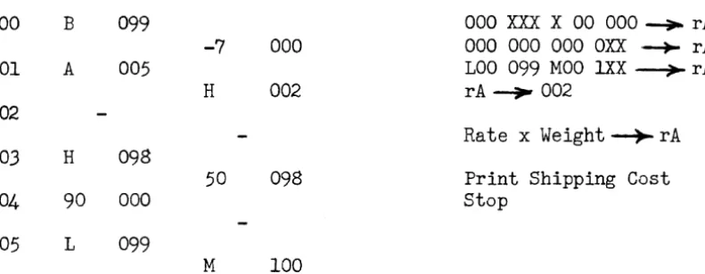
shipping rate table of 100 entries is stored in memory cells 100-199. The rate in cell 100 is the cost/pound to be levied for all it~ms of weighto
to 99 pounds. The rate in cell 101 applies to 100-199 pound items, etc., in memory cell 099 is the weight of an item to be shipped, within the range of the table, in this format:000 XXX ~OO 000
Thus, a weight of 3523 pounds would be stored in 099 as 000 352 300 000. The rates are given in dollars and cents/pound in the following format
(the example is $2.36/lb.):
000 ~36 000 000
Compute and print the shipping charge.
ex-000 001 002 003 004 005
B 099
A 005
H 098
90 000
L 099
-7
000H 002
50 098
M 100
000 XXX X 00 000 -+- rA 000 000 000 OXX --+- rA LOa 099 MOO lXX ~ rA
rA~ 002
Rate x Weight ~ rA
Print Shipping Cost stop
A simple modification allows us to do table look-up problems when the table arguments are not multiples of 100. For example, suppose these same rates applied to shipping weights in intervals of 250 pounds. Now, if we multiply the weight by 1/250 (=.004), we have the number of 250 pounds units, which is in one-to-one correspondence with the memory address of the rates.
000 001 002 003 004 005 006
L 099
-5 000
H
003H 098
90 000
000 400
007 LOa 099
M 006
A 007 00
coo
50 098
000 000
MOO 100
OOX
xxx
~OO 000 ~ rAWeight/250
=
000 OOX X 00 000 ~rA 000 000 000 OXX~rALaO 099 MOO lXX~rA
rA--+003
Rate x Weight~ rA
Print Shipping Cost Stop
SECTION IV
Instruction List
g
(continued)~ This instruction duplicates in rF, which is a one word register, the contents of memory cell m.
~ This is the extract instruction. The contents of rA are selectively re-placed by the contents of m. The word in rF, called the extractor, governs the transfer. Of the 63 Univac characters, every other one, starting with the ig-nore (i) extracts, in particular, the 1. Thus, if the initial contents of rA, rF, and mare:
m: 123 ABC 789 DOE rF: 010 110 001 101 rA: 987 6DE 017 54G
And the instruction E m is given, the contents of rA will be:
rA: 927 ABE 019 D4E
Two examples will illustrate some of the uses for this instruction.
In memory cell 100 is a quantity in the following format:
000 XXX
xxx
XX~Which we desire to print on the supervisory control printer, suppressing the non-significant zeros. That is, if 100: 000 000 690 760 we wish to print 690 760 only.
000 L 100 000 XXX XXX XXX.-,-.. r L
B 006 001 --- --- ---~ rA 001 -1 000 Shift rA right one place
T 001 Transfer control if rA> rL
002 H 008
]
rA~rFF 008 003 B 007
E 100
NYl
!lbA
~W1 ----..,..
r A 004 H 000Note that in line 001, the iterative portion of the routine, the word in rA is successively shifted to the right until the 1 lines up under the left-most non-zerO digit of the word in cell 100. The ones and dashes then can be used as an extractor, replacing the space symbols with the most significant digit of 100
and all digits to its right. The space symbols, of course, move the typewriter carriage but do not print. If we were to print a column of numbers edited in this fashion, they would be aligned on the least significant digit. If we wished them aligned on the most significant digit, we would replace line 007 with ignores: iii iii iii iii.
Suppose, now, that the word in 100 is in the following format:
100: 000 XXX ~X XXX
where"indicates the position of the assumed decimal point. We wish to print this number with dec~al point, and nonsignificant zeros suppressed. That is, if 100: 000 003 607 690 we will print 360.7690. The first step is to "spread" the word apart and insert the decimal point, then zero suppression.
000 B 100
001 H 014
002 A 010 003 E 014 004 L 014
005 -1 000
006 H 015
007 B 013
008 H 014
009 90 000
010 000 000
all 001 III
012
01-013 MI:l .bAA
014
015
01 000
-1 000
F all
H 014
B 012
T 005
F 015
E 014
50 014
00 000
0.0 000
100 000
~ AAA
000 XXX XX"X XXX ~ rA
OOX XXX X /\
xx
XXO--+ rA rA--+
Working Storage000 XXX XXX XXX ---4-r A 000 XXX X.X XXX ~ rA
001 III 100 000 ---?-rF OOX XXX
x.x
XXX ~ rA rA---4-- Working StorageZero Suppression
SECTION 1
Introduction
CHAPTER 5 INTERNAL ITEM PROCESSING
Most of our study of computer applications so far has concerned itself with single units of information. In a few problems we saw that the processing required several bits of data before the computation could begin. This leads us to the concept of the item. An item is a set of related data, called fields, which may be treated as a unit. The composition of an item (that is the
fields of which it is composed) may depend on the processing to be done, the policies of a company, or the manner in which the data is obtained. Bearing these reasons for variation in mind, examples of typical items are given below:
~ Master Employee Item
1) Name and Address
2) Badge or Employee Number 3) Rate of Pay
4) Number of Dependents
5) Type of Standard Deductions 6) Work and Pay Summaries
A
Stock Inventory Item1) Stock Number 2) Description 3) Unit of Measure
4) Lead Time for Ordering 5) Unit Cost
6) Amounts on Hand and on Order
~ Public Utility Meter Item
1) Account Number 2) Current Reading 3) Last Reading
4) Keep item sizes as small as feasible, bearing in mind the number of instructions required to "move" the item about and the possi-bility of future expansion.
The stock inventory and utrlity meter items are pictured below to illustrate the appearance of an item.
The item notation used throughout this course is a simple one and yet is flexi-ble and unambiguous. A letter will stand for the set of all items of a particu-lar kind, a subscript defining a specific item of the set. A superscript will serve to identify the field under consideration. For example, let S stand for all stock inventory items, then Si is the ith such item, while
S~n
1 is the Stock number of the i th inventory item
s?
"
" Description " ""
"
" 1SU
"
tIUnit of Measure of the ith inventory item
Etc
Stock Inventory Item
I : :
:StO~k
N;ber:
I
I
: :
Dfscripti
°7
i
I
:DescfiPtitn +nt):
I
~~!;u~!
:
I
[
0: On rand:
I
I
0~n
or~er
I
I
0:uni
t:cos~
0 0 Lead,
Tire
I
A
Public
:ti
1
r\
M:te:
:It:m :
I
Ac~ount:Nun~er
0 0:
0I
SECTION 11
Instruction List Q
To facilitate the movement of items inside the computer, two multiple word transfer registers have been provided.
Register V, rV, a two-word register Register Y, rY, a ten-word register
Instructions affecting these registers are:
V m, This instruction causes the contents of memory cell m and m
t
1 to be duplicated in rV. For our purposes m must be a multiple 'of two; that is, an address like 000, 102, 504.~ This instruction causes the contents of rV to be duplicated in memory cells m and m
+
1. Again, m must be a multiple of two.To illustrate these orders, suppose memory cell 100 contains a quantity A, and cell 101 a quantity B. If the order V 100 is given and at any later time W 304, say, cell 304 contains A and 305 B. The contents of rV are not destroyed upon reading out.
Y m, This instruction causes the contents of cells m, m t 1, ••• , m t 9 to be duplicated in rYe m must be a multiple of ten.
Z m, This instruction causes the contents of rY to be duplicated in memory cells m, m + 1, ••• , m t 9. Again, m must be a multiple of ten. The contents of rY are not destroyed upon reading out.
For example, if Y 100 is given, then a Z 310,
100: A 101: B And: 102: C
109: J
310: A 311: B Then 312: C
SECTION III
Working Storage
The following problem will illustrate the multiple word transfer instructions and the most efficient means of item handling.
6 ten word items are stored in memory cells 100-159. Then item layout is:
.Tnh Numhp-l"
Contract Price
Labor Cost
\ Material Cost
Overhead Cost
OTHER
DATA
Compute the net profit and store the job number and profit as a two-word item in cells 160-171.
We shall solve this problem in two ways. In the first let us code the steps necessary to process the first item (100-109) and store the desired fields in 160-161 and then process the remaining items by appropriately increasing the address part of the instructions referring to those locations:
000 B 100
001 B 101
002 S 103
003 H 161
004 L 012
005 A 013 006 B 001
007 H 001
008 A 014
009 B 003
010 H 003
H 160
S 102
s
104B 000
Q 011
H 000
A 014
B
002 H 002A 015
U 000
Job Number-+ 160
)
) Net Profi t~ 161
)
Transfer C9ntro1 if last item
) )
)
)
) Augment Addresses
all 90 000 Stop 00 000
012 B 150
H 170 013 000 010
000 002 014 000 010
000 010 015 000 002
000 000
Now, if we recode the problem, this time instead of increasing all instructions, which refer to addresses 100-109, we simply transfer the next input item into the position occupied by the first item.
000 B 101
S 102
001 S 103 Net Profit ;am 101 S 104
002 H 101
V 100 Store Computed Item
003 W 160
Y 110
004 Z 100 Replace 100-109 with next item
B 003
005 L 009
Q 008 Transfer if last item computed 006 A 010
H 003
007 00 000
U 000
008 90 000 Stop
00 000 009 W 170
Y 160 010 000 002
000 010
effi-Student Exercise
1. Memory locations 100-159 contain a series of two word census items:
ass
000 CCC COO OAA AOM OHO OOGWhere SS CCCC
AAA
M
is a two digit state code " "four "city "
fI the individual's age
" " "marital status
S
=
Single M=
MarriedW
=
Widowed D=
DivorcedH is the individual's race W
=
WhiteC
=
Colored G is the sexM
=
Male W = FemaleSECTION IV
Variable Connectors
You recall that the fixed connector was used on a computational flow line to indicate a merging of flow lines. Its counterpart, the variable connector, is used where flow-lines diverge.
Suppose we have a problem to code requlrlng us to send Type A items through process 1 and then through process 2, while Type B items must go through process 1 then process 3. The normal procedure would be to repeat process 1 along the A flow
line and B flow line:
A Items
Process 1 Process 2
B Items
'1
.... .... ....
Process 1
-
Process 3-If process 1 is a complex and extensive calculation it becomes highly inefficient to repeat it along every flow line requiring it. The suggestion immediately presents itself of doing process 1 once only and funneling both items through it, separating them again after completion of process 1:
A Items
Process 2
Process 1
The switch is called a "Variable Connector" and is indicated by:
~--
...
The letters of the Greek alphabet are used to designate the variable connector. The act of setting the connector is shown by the symbol.
---~~~~~---~~~
Which implies that, after passing through the box, when we encounter the con-nector ~ it is set to read 0<1. Our example would now appear:
~
Process 2~p_r_o_c_e_s_s
__ l __~1 ~
~
Process 3This makes evident that a variable connector is the same as a fixed connector, but the number the connector transfers us to is determined when the connector
is "set".
To illustrate the use of these connectors, consider the following problem:
6 ten-word "A" items are stored in memory cells 100-159. Each item has a serial number as its first word and the items are in ascending order by this serial number. Similiarly, 6 ten-word "Bit items are stored in 200-259. Merge (interfile) these items together, storing the merged results in 300-419.
000 B 100
L 200
001 00 ' 000
T 012 Transfer Control if AS~'->Bj~
002 y 100 Ai~Ck
Z 300
"
003 B 002
A 023
004 H 002 k'" l~k
B 012,
005 A 023;
H 012.
006 B 009
L 024
007 00 000
Q 011 Transfer Control if i
=
6008 A 025
H 009
009 y 100 i t ~i
Z 100
010 00 000
U 000 Variable Connector ~
011 V 026
W 020 Variable Connector
8
(.0( 1 and .~ 2-)012 Y 200
Z 300 Bj~Ck
013 B 012
A 023
014 H 012 k t l-~k
B 002
015 A 023
H 002
016 B 019
L 030
017 00 000
Q 021 Transfer Control if j
=
6018 A 025
H 019
019 y 200 j
+
l---+jZ 200
020 00 000 Variable Connector"
U 000
021 V 028 Variable Connectory
VI 010
·
~2 and·V'2.
022 00 000
023 000 000
000 010
024 y 150
Z 100
025 000 010
000 000
026 00 000 ~
U 012
027 90 000
00 000
028 00 000
U 002
029 90 000
00 000
030 Y 250
SECTION 1
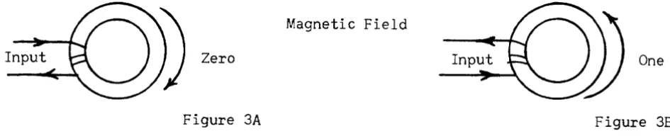
Characteristics of Magnet Tape
CHAPTER 6 INPUT-OUTPUT
As mentioned in Chapter 1, magnetic tape forms the principal means of introducing and removing information from the Univac. Physically, the tape is a metallic strip about 1/2 inch wide and .002 inches thick. It can be supplied in reels of various sizes, the longest being about 1500 fe~t. Metallic tape is used because of its excellent resistance to moisture variations and fire, as compared with paper or plastic tapes. Certified tests have shown the tape to be readable after direct contact with temperatures as high as 550°F. An outstanding
characteristic of metallic tapes is their reuseability. Information may be recorded on a tape, read, erased and new information recorded on this same tape, thus cutting the cost of supplies considerably. A reel of tape can be read or written upon nearly 1000 times before showing appreciable wear.
Univac characters are recorded serially along the length of the tape at varying densities, up to a high density of 128 characters/inch. A full reel of tape, 1500 feet, can hold as much as 1,440,000 digits, in a cubic space of less than 40 inches, providing a compact information storage medium, which is nearly age proof, without the necessity of moisture or air conditioning. Information recorded on tape is in block form, 720 digits or 60 words to a block. Block recording is used to permit very high reading and recording speeds, a
necessity in data processing problems. The 60 word block was chosen as a programming convenience. This block size permits the greatest variation of item size which still retains an integral number of items per block. Thus, a block may consist of
60 1 word items 6 10 word
.
~1 Lems
30 2
"
" 5 12"
"20 3
"
"
4 15"
" 15 4 " tt3 20
"
" 12 5"
"
2 30"
"
10 6"
ItSECTION 11
Recording 20 Tape
Three means, at present, are available for recording on tape:
Key Board to Tape Recording:
Unityper 1 is a device for converting a typist's key stroke onto magnetic tape. This device ontains automatic checking features on the typist. By properly pre-paring punched paper tape loops, a forced check can be made, preventing the typist from under- or over- typing a field. These loops also provide for automatically filling complete or partial fields with zero, space, or ignore symbols. By operation of an erase key the typist can backspace the tape and re-record if she detects a typing error. The output of Unityper 1 is magnetic tape recorded at a density of 20 characters per inch. A Uniprinter may be plugged directly to the typer to obtain a printed record of the typing (see Uniprinter).
Unityper 11 is a smaller and simpler keyboard-to-tape recorder suitable for volume data recording. It consists of a sl~ghtly modified Remington Electric typewriter with an integrally attached tape mechanism and power supply and can be mounted on the normal typist desk. As each key is struck, the character is printed and also recorded on tape. Similar erasing and
fill-in features are provided as fill-in the Model I Unityper, but no loops for forced check on field size have been included. Each line of print (120 characters) is recorded on tape as a ten word item. The recording is at a density of 50 characters/inch.
Card To Tape Recording:
SECTION III
Reading Tape
Tape To Printed ~:
The High Spe.:d, or line printer is a device for large volume printing of the data recorded on magnetic tape. Each ten-word item recorded on tape at 128 characters/inch printed on a 120 character line, or, if desired, through format plugboards, selected fields of the item may be printed on as many as six different lines. Through use of these same plugboards the digits in the 10-word item may be printed in any desired column, and provision is also made for automatically suppressing nonsignificant zeros. A punched paper tape loop controls the vertical format of the printing. The present model uses continous form stock, although a cut form attachment is in development. The rate of printing will of course depend on the vertical format to some extent, but speeds of 300 to 600 lines peT minute are obtainable. The speed is variable depending on the number of carbons desired. The printer can print any of 51 characters. The checking features include an odd-even and 120-character check on the reading from the tape, a check on the internal memory, and a check on the proper firing of the print hammers.
The Uniprinter is an electric typewriter, identical in its action to the Super-visory Control Printer except its input as magnetic tape, recorded at the low
density of 20 characters/inch. The Uniprinter is used where low volume printing of extreme flexibility in form is desired. The printing rate is about 8-10 Characters/second and the typing format is controlled by type-writer control symbols recorded directly on the tape with the data. In this manner, the typing format can be as variable as that obtainable from a typist.
Tape To Punched Card:
The magnetic Tape-Io-Card Converter produces an 80 column punched card from each 10-word item recorded on tape. A plugboard allows the selection of any 80 digits of the item to be entered in any of the 80 card columns. The
checking features are the odd-even check and a 120-check on reading from tape, memory check, and a comparison of the punched card with the data stored in the memory. The conversion takes place at a rate of 120 cards/minute with tape recorded at a density of 128 characters/inch.
Tape To Computer:
This is accomplished by Uniservos which are described in Section IV.
-53-SECTION IV
Uniservo
Communication between the Univac and the auxiliaries described in Section II and III is established through magnetic tape. The Uniservo is the means by which the Univac reads or records magnetic tape. As many as ten Uniservos may be connected to the Univac at the present time. They are numbered from
1 to 9, the tenth being labeled the -. A Uniservo may read or write tape at the discretion of the program, and is two-directional in its action. In defining the direction of tape motion we shall use the simplified picture shown below.
Left Reel
Read-Write
Head Right Reel
A reel of tape is always mounted on the left reel. It is connected to a pre-threaded leader which is permanently fastened to the right reel. Removal of a:reel of tape and IOOtlnting a new reel takes about 1/2 minut-€-~ When tape is moving from the left reel to the right reel, we say the tape is moving in the forward direction. When tape moves from the right reel to the left, the tape is said to be moving backwards.
SECTION V
Instruction List
g
5n m, This instruction causes the computer to write on Uniservo n (n
=
1, 2, ... 9,-) the block, 60 words, from memory cells m,m - l, ... m - 59. m must be a multiple of ten. The writing is at the high tape density of 128 characterslinch, with the tape moving in a forward direction. The write instruction
is carried out in three steps:
a. Another write instruction is not still in progress b. The last write was properly executed
c. Uniservo n is free (not engaged in a rewind or read instruction)
If all of the above queries are answered affirmatively, it proceeds to step two; otherwise, it remains at step one until all queries are answered yes. These queries are called the write interlock tests.
2) The block in m through m t 59 is transfered to the 60-word output register, rO, and Uniservo n is started. At this point the central computer is released to continue executing instructions, the output control circuits taking over control.
3) The block in rO is recorded on tape, first the word that came from cell m, then m
t
1, etc., and last to be recorded is the word from cell m + 59. Within each word, the first character recorded is from digit position 1, then, 2, and finally position 12. After the la& word is recorded the tape stops and Uniservo n is free as also arethe output circuits.
7n m, This instruction is identical to the 5n m instruction, except the write density is 20 characters to the inch. This density is used only when the tape is to be printed on the Uniprinter.
In 000, This instruction causes the computer to read into rI in a forward direction (the block just to the left of the read-write head on Uniservo n). The read instruction is carried out in two steps.
1) The computer determines whether:
a. Another read instruction is not still in progress b. The last read was properly executed
c. Uniservo n is free (not engaged in a rewind or write instruction)
If all of the above queries are answered affirmatively, the computer proceeds to step two, otherwise it remains at step one until all queries are answered yes. These queries are called the read interlock tests.
2n 000, This is the backward read instruction, and is identical to the In 000 instruction, except that the block read into rI is the one tq the right of the read-write head, the tape moving backwards. Even though the block is read back-wards, its appearance in rI is the same as though it were read forward.
30 m, This instruction causes the computer to transfer the block in rl to memory cells m, m
t
1, ••• , mt
59. rl is cleared only after the transfer. m must be a multiple of ten.This instruction is carried out in two steps:
3n m,
4n m,
1) The read interlock tests (desc!ribed under the In 000 instruction) are performed. If they are answered yes, step 2 is executed.
2) The 60 words stored in rl are transferred to the memory beginning with cell m, the last word in rl going to cell m
+
59. Aftercompletion of the transfer, the computer is released to continue executing instructions.
This is a composite instruction, performing first a 30 m, and then a
This is a composite instruction, performing first a 30 m, and then a
In 000.
2n 000.
6n 000, This is the rewind instruction, causing all of the tape on the right hand reel to be passed over to the left reel. This instruction is executed in two steps:
1) The write interlock tests are performed.
2) The Uniserve n is started, moving tape backwards. At this point the central computer is released and the rewind control circuits continue the rewind process.
At the conclusion of the rewind, the tape may be read forward or written upon.
8n 000, This is the Rewind with interlock instruction. Its action is identical with 6n 000 instruction, except, at the completion of the rewind an interlock is
set for Uniservo n.
Whenever Uniservo n is called for again to either read, write or rewind it always sends back a "busy" signal, stopping the computer on the appropriate interlock tests. This instruction is used when a rewound tape is to be removed and a new tape mounted in its place. The removal of the reel of tape and the mounting of a new reel removes the busy signal for Uniservo n.
Stock Npmber
Inventory
The number of such items is unknown but a Z sentinel follows the last item. An equal number of two-word items
are recorded on Tape 3. sequence on both tapes.
Quantity Used
The stock numbers are assumed to be in the same Produce a corrected inventory on Tape 4.
Let us label Tape 2 as T2, a block (30 items) from this tape, A, eac8 of the thirty items Ai' and the stock number of an item Arn , the quantity Ai
Tape 3 is labeled T3, a block from the tape, B, an item of the block Bi and the stock number and quantity
Br
n , B~.000 12 000
001 33 100
002 B 100
003 00 000
004 B 101
005 H 101
006 L 019
007 A 020
008 B 004
009 H 004
010 A 020
011 00 000
012 54 100
00 000
32 200
L 018
Q 015
s
201B 002
Q 012
H 002
A 021
B 005
H 005
U 002
B 024
T2 ---+- rI
rI ---+ A, T3 ~ rI
rI~ B, T2~rI
Transfer control
t
A9 -
B~~
AQJ
1 1 i' - - - - " ' - . . I r I --;> A rI--;> B
~-...c. 2
013 H 002
V 022 1 ~ i
014 W 004
U 001
015 54 100 A ') T4
82 000
016 83 000 Rewind W/Interlock T2, T3, 84 000
017 90 000 Stop
00 000 018 ZZZ
zzz
ZZZ ZZZ 019 B 158
L 018
020 000 002
000 000 021 000 002
000 002 022 B 101
S 201 023 H 101
B 002
024 B 100
L 018
Student Exercise:
A tape on Uniservo 1 contains a series of two word meter consumption items
ConslUDption
The number of such items is unknown but a Z sentinel follows the last item. Produce and print the follow-ing table:
Consumption Range
1-100 101-500 501-1000 1001-over
Consumption Accounts
3600 500 T
SECTION VI
Filling Register
I
In most phases of complex commercial applications of UNIVAC, data from several different sources must be brought together before computation on this data can proceed. The information coming from these different sources are recorded o