BOREHOLE MODEL FOR SIMULATION TRANSPORT GEOTHERMAL
HEAT WITH HEAT PIPE SYSTEM AND WITH FORCED CIRCULATION
OF HEAT CARRIER
Michal JAKUBSKÝ, Richard LENHARD, Martin VANTÚCH, Milan MALCHOx
Abstract: In the call OPVaV-2008/2.2/01-SORO Operational Programme Research and Development - knowledge and technology transfer from research and development into practice (ITMS-26220220057), whose strategic goal is "Device to use low-potential geothermal heat without forced circulation of heat carrier deep in the well "in the Department of Energy laboratory techniques to construct a simulator of transport low potential of geothermal energy in comparative test-drilling in the laboratory. The article describes a device that was designed as a scale model of two deep boreholes each of which withdraws the earth's heat by heat transfer technology and heat carrier. Device using forced circulation of heat carrier will respond in the construction of equipment currently used to transport heat from deep borehole. As the heat carrier will be used CO2. Facilities without using forced circulation of heat carrier, the new technology, which will be used as heat carrier ammonia (NH3).
1. I
NTRODUCTIONThe simulator is a device that was designed as a scale model of two wells each of which removes the earth's heat by other technology and heat transfer substances. The basic idea consists in an imitation process in the soil, namely the accumulation of heat in the ground from sunlight and heat energy from Earth's heat. In this case, the heat is replaced by electric heating cable placed around the circumference of the cylinder - bore (Fig. 2.c.).
Figure 1: Device No.1 with 4 heat pipes (top left) and device No.2 with two U-tubes (bottom left down) and the upper heat exchange section (right)
x Ing. Michal Jakubský, Katedra energetickej techniky, Strojnícka fakulta, Žilinská univerzita v
Žiline, Univerzitná 1, Žilina, tel.(+421) 41 513 2866, e-mail: michal.jakubsky@fstroj.uniza.sk
Heating and subsequent removal of accumulated heat using existing and new technology will allow us to their comparison and evaluation. Equipment using forced circulation of heat carrier (4 heat pipes) will be answered at present construction of equipment used to transport heat from a deep borehole. Heating medium will be used CO2. A facility without
using forced circulation of heat carrier (2 U-tube) is a new technology which is used as heating medium ammonia (NH3). (Lenhard, R., Jakubský, M., PCO 2010)
This project aims to design and verify the appropriate construction heat pipe with a given working substance, and the construction for the transport of heat from a deep borehole in the heating medium. Based on available knowledge of heat transfer, construction of boreholes and geological composition of soils as well as a geothermal gradient was prepared engineering design simulator.
2. C
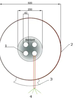
OSTRUCTIONThe device is folded from a few simple components. PVC pipe diameter D = 500 mm and height is around 5 m hole in a cylindrical shape. It´s a cylinder where heat will be accumulate and subsequently collected. To the tube is insert PVC pipe with a diameter of 200 mm and a height of 5 m. With terminative equipment’s is ensured concentricity smaller pipe in a bigger pipe. This pipe (200 mm) represents itself bore where are located heat pipes (device # 1) or U tube (device # 2). Remaining volume is filled with a mixture of bentonite, which is a standard substance used in bore hole digging to better heat transfer. Between circular spaces is filled with wet sand (soil around the borehole) whose thermal conductivity is 1.63 W.m-1 K-1.
After the outer circumference of pipe (500 mm) is wound in a spiral shaped electrical heating cable 10 W / m (replaced by accumulation of solar radiation into the earth and the earth's heat). Cable diameter is 6 mm and 10 mm spacing (Fig. 2c). When installing the heat cables, we used aluminium tape, which helps remove heat from device to borehole simulator.
Electric heat cables of this type are used to protect pipes against freezing or maintaining desired temperature flowing medium, namely heating pipes, as in our case.
Figure 2: a) the basic structure of the borehole, b) sand-rock surrounding a borehole, c) el. heating cables
Heating drilling simulator is divided into three sections (3 x 100 m cable), the simulation needs = different depths with different temperatures. Incandesce cable is insulated with aluminium tape. Heating power cables is so directed toward to hole and is prevented by external temperatures. Thus accrue "earth heat" to model the borehole and then using it in tubes and heat pipes will be taken.
Figure 3 is a cross-section model of the borehole, which forms outer layer of reflective tape insulation. Between circular area consists sand in which is introduced protective tube with 4 thermocouples. Location of thermocouples across the entire district bore to the heat pipe allows us to record heat-keeping temperatures in the "soil".
Since borehole temperature rises on geothermal gradient, we need recorded temperatures not only toward to the center hole but throughout its depth. Therefore, on full amount hole are fixed six protective tubes with 4 thermocouples on each of them. Overall, we therefore record temperatures from 24 points placed at different heights and distances from the center of borehole (Figure 4). (Lenhard, R., Elsevier 2011)
Figure 3: Cross-section of the device and the introduction "protector" wit Thermocouples (1 – Bentonite, 2 – Heating pipes, 3 – Isolation, 4 –
Thermocouples)
At the same time of assembly and installation of thermocouples ran coolant for heat removal from the borehole. In the last stage of the project to complete CO2 and NH3
introduced into a control panel. Built measuring position with PC records actual temperature across the cross section of a borehole. With software we are able to record the following data: flow rate in kg / min to return coolant, inlet and outlet coolant temperature in exchanger, respectively NH3 CO2 pressure, power output level in each
borehole sections. Analogously it is possible to read the pressure at the inlet and outlet coolant. In cooling circuit is as a device for heat removal from the borehole connected heat pump Vitocal 300BWS with 8.4 kW power and cooling thermostat Julabo FL 2503 with a temperature range from 40 to -20 °C.
Figure 4: From engineering design to implementation
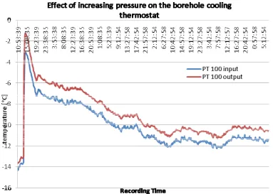
Figure 15 Increasing the input and output coolant temperature after the heat pipe filled with CO2
5. C
ONCLUSIONIn the current state of development of the project is fully operational simulator No.1. Simulator # 2 will be operational after filling ammonia, due to the nature of this medium is a complicated process. Previous results have verified the functionality of the device, the heating and cooling. The system continues to perform and cooled to the desired pressure. It is already clear, however, that the cooling circuit diagram applies in its entirety. If the cooling medium in this case, CO2 in the gaseous state it is not possible
after the temperature in the circulatory system's temperature in the lowlands drilling simulator. To work we have done by increasing the pressure to pass into a liquid form of CO2. Such dependencies are subject to further testing and measurement. The current
situation could be described as a test, and the author himself verifies functionality of the device and its behavior in various model situations.
A
CKNOWLEDGEMENTSThe article was prepared under the Operational Program Research and Development, ITMS - 26220220057 "Zariadenie na využitie nízkopotenciálneho geotermálneho tepla bez núteného obehu tepelného nosia v hlbokom vrte".
6. R
EFERENCESrecorded initial state that is to say status prior to power electric heating cable, when the individual affected by temperature alone position sensor and the ambient environment (solar radiation penetrating through a skylight in the laboratory). Several hours followed by 780 W power output throughout height of device. Figure shows state before accumulation, charging several hours and steady temperatures. From chart can be read an abnormal rise in temperature measuring point T19, where was a failure in joint connector introduced into the panel. Error was corrected exchange connector. Measuring points of higher numbers, such as T24 reaches higher temperatures, because of their location near the roof of the laboratory (Figure 9).
Figure 8: Temperatures of the device with heat pipe when running power 780 W
response time of thermocouples
before to the heat pipe
response time of thermocouples
in the sand 2
response time of thermocouples
in the sand 1
reaction time of peripheral thermocouples time of heat transfer the perimeter radius
10:21 10:19 10:01 9:58 24 min
section 3 10:36 10:20 10:04 9:58 39 min
10:21 10:21 9:59 9:58 24 min
section 2 10:44 10:23 10:07 9:59 47 min
10:29 10:09 10:01 9:59 32 min
section 1 10:27 10:05 10:00 9:58 30 min
24-47 min 8-26 min 2-10min 1-3 min 24-47 min
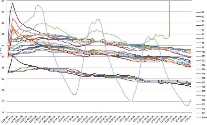
Figure 9 shows a 3-day of temperatures in the simulator, along with ambient temperature (T - ambient, blue colour), which was measured under the roof of laboratory. Record was launched on a day when the air temperature reached 36 °C. Next two days following the decrease in air temperature of 15 °C. It was a large temperature fluctuation in the second half of August 2011. From the record it is clear that difference between night and day temperatures influence of temperatures in borehole is minimal. Thermocouple number 21 recorded during the measurement of abnormal temperature rise, causing damage to contact directly in the borehole. Errors following findings have been allayed.
Figure 10: Effect of ambient temperature in the borehole model
From previous measurement was recorded temperature (Figure 11) before the accumulation of heat in the simulator, temperature after several hours the power supply output 780 W. For this record are clear differences between peripheral temperature thermocouples (maximum t) and thermocouples the nearest to heat pipes (minimum t). Another recording was performed the next day. Differences between the measurement points are settled and there was a steady temperature across of the simulator. With an
interval of 30 days was recorded temperature state of simulator with minimal differences compared to the previous state. This minimum difference confirming functionality of the insulation and prevent heat accumulated losses towards the surroundings.
Figure 11: Recording condition temperatures in intervals
4. T
EST MEASUREMENTS THE HEAT REMOVALPrevious measurements were carried out without heat removal. The system was not involved in any appliance that would take the heat exchanger of the device. Given the current state of the project to test out for the heat removal device No. 1, which is for a system with 4 heat pipes. As the "appliance" We used circulatory thermostat Julabo FL-2503 with the refrigerant thermal G for temperatures from - 30 °C to 80 °C. The aim was to model all drill cooled with high average temperatures around 26 °C at subzero temperatures and pressure dependence monitor CO2 and temperature in the simulator.
Circuit was filled with CO2 at 3.9 MPa pressure and circulatory thermostat set at -20 °C.
Due to high temperature in the lab-25 °C, the thermostat was not able to reach this temperature.
Coolant inlet temperature to the heat exchange surface bathe CO2 exchanger was on
average - 14 °C. Figure 12 shows the pressure drop within a few hours. The pressure drop of 1 MPa occurred within 40 hours, which were also the greatest decrease of temperature in the simulator (Figure 13) and the whole of borehole temperature drops ranging from 15 to 25 °C.
Figure 13: Reduce pressure with decreasing temperature
Record before and after the heat pipe filled with CO2 to a pressure of 3.9 MPa is shown in
Figure 14, where the greatest drop in temperature during the decrease of pressure of 1 MPa. Subsequently, the temperature dropped to minus values. Measuring points on the circuit simulator, that is furthest from the heat pipes to maintain this record for plus temperatures, the temperature is far from the "fall" on average about 25 °C.
Figure 15: Increasing the input and output coolant temperature after the heat pipe filled with CO2
5. C
ONCLUSIONIn the current state of development of the project is fully operational simulator No.1. Simulator # 2 will be operational after filling ammonia, due to the nature of this medium is a complicated process. Previous results have verified the functionality of the device, the heating and cooling. The system continues to perform and cooled to the desired pressure. It is already clear, however, that the cooling circuit diagram applies in its entirety. If the cooling medium in this case, CO2 in the gaseous state it is not possible
after the temperature in the circulatory system's temperature in the lowlands drilling simulator. To work we have done by increasing the pressure to pass into a liquid form of CO2. Such dependencies are subject to further testing and measurement. The current
situation could be described as a test, and the author himself verifies functionality of the device and its behavior in various model situations.
A
CKNOWLEDGEMENTSThe article was prepared under the Operational Program Research and Development, ITMS - 26220220057 "Zariadenie na využitie nízkopotenciálneho geotermálneho tepla bez núteného obehu tepelného nosia v hlbokom vrte".
6. R
EFERENCES[2] Lenhard R., Malcho M.: Numerical Simulation Device for the Transport of Geothermal Heat with Forced Circulation of Media: Elsevier-An International Journal: Mathematical and Computer Modelling. - ISSN 0895-7177, doi:10.1016/j.mcm.2011.06.011
7. F
URTHER READING[3] Nosek, R., Jurkechová, J., Papuík, S., Jandaka, J.: Influence of fluel supply to in small capacity boiler on efficiency and pollutant emisions, Experimental Fluid Mechanics 2010, Liberec, p. 458, ISBN 978-80-7372-670-6
[4] Müllerová, J.: Ako ušetri náklady na vykurovanie. Štýl pre váš interiér a exteriér, II/2002, kontakt/juven Žilina, s.18-19, ISSN 1335-8901
[5] Jakubský, M., Lenhard, R., Vantuch M.: Simulátor transportu geotermálneho tepla, Energetika a životní prostedí 2010, Ostravice 2010, p. 40, ISBN 978-80-248-2286-0.