300 |
P a g e
COMPARATIVE STUDY OF PID AND FUZZY
CONTROLLER ON EMBEDDED COMPUTER FOR
WATER LEVEL CONTROL
A G Suresh
1, Jyothish Kumar S Y
2, Pradipkumar Dixit
31
Research scholar Jain university, Associate Prof of EEE dept, BTLIT College, (India)
2
Assistant Prof of EEE dept, BTLIT College, (India)
3
Associate Prof MSRIT College,(India)
ABSTRACT
This study deals with one of frequently encountered tasks in process industry – accurate water level control.
Proportional Integral Derivative (PID) control is often used for this purpose. Since control parameters of PID
controller are fixed and tank system is inherently nonlinear, PID controller should not be used on wider level
range. Therefore this study analyzes the effectiveness of water level control using fuzzy controller. The fuzzy
controller is implemented based on mathematical model of tank by using MATLAB Simulink. The graphical user
interface (GUI) is designed by using LabVIEW software and PID and fuzzy controllers are implemented on
Microcontroller board. Microcontroller board is used as an acquisition board for collecting Ultrasonic
Sensor data from level of water in tank system and as a voltage generates for water pump to pump the water
into the tank. Experimental results confirm that the fuzzy control system has good adaptability in comparison with
PID and provided satisfying results.
Keywords:
Fuzzy, PID, Nonlinear System, Pump, PC, Tank, Ultrasonic Sensor, Pump Drive,
Water Level Control.
I. INTRODUCTION
In certain industry branches like food, pharmaceutical, chemical, filtration, nuclear power generation plants,
spray coating, etc the problem of water level control is very often encountered. The main objective of
controller in this case is maintaining different setpoint water levels, mostly, in real time environment. The
traditional approach to this problem using PID controllers is not fully convenient when it comes to
dealing with nonlinearity of tank systems and their complexity in industry. These problems can be
successfully dealt with using fuzzy control Based on expert knowledge and experience, control
implementation is therefore simplified, and it can be achieved without complex mathematical modeling. Since
the water level controller is often a part of complex control system, the controller should have a
communication interface which allows it to be incorporated and integrated with centralized control system.
Different communication interfaces makes it suitable for use in already existing control systems, without
301 |
P a g e
implementation of PID and fuzzy water level controller using embedded computer(PC) and comparison of
these controllers on laboratory tank mode.
II. SYSTEM DESCRIPTION
Figure 1 shows the block scheme of implemented control system.
Fig 1. System Structure
The PID and fuzzy controllers are implemented in application developed for PC, which allows user to
set desired water level and to select the type of controller (PID, or fuzzy). It also displays measured water
level. Regardless of controller type, controller input (or one of the inputs) is measured water level expressed
in centimeters, and its output is duty cycle of pulse width modulated signal, expressed in 8 bits digital form
proportional to percentage of duty cycle Both, controller input and output are exchanged with Micro
processor Development Board. Micro processor is used as an acquisition input/output card for PC. Micro
processor and PC are connected using USB interface. The PWM signal is used for triggering of pump driver which
generates a voltage signal used for pump control. Measurement of water level is done using ultrasonic sensor
and analog to digital and voltage to water level conversion on Micro processor.
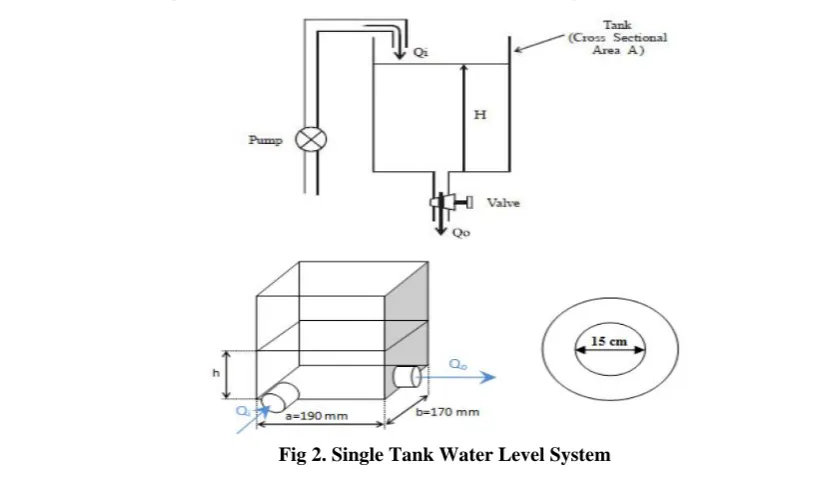
III. SYSTEM IDENTIFICATION AND MODELLING
3.1 Mathematical Modeling
The structure of the liquid volume in horizontal tank and its geometrical parameters are shown in Figure 2
302 |
P a g e
The system model is determined by relating the flow Qiinto the tank to the flow Qoleaving through the valve at
the tank bottom. Using a balance of flows equation onthe tank, it is possible to write:
Qi (t) – Q0 (t) = A
dh (t)
dt (1)
Where A is the cross sectional area of the tank and his the height of the water in the tank.
The Bernoulli's equation can be adapted to a streamline from the surface to the orifice as:
g z1 +
p1
ρ + v1
2/2 = g z 2 +
p2
ρ +v2
2/2 (2)
Equations (1) and (2) refer to two different points in the flow, first being upstream of second point. Vis the local
velocity of the water; grepresents the local acceleration of gravity, pthe pressure and zthe vertical height of the
point.
If Bernoulli’s equation including loss is applied to single tank system shown on Figure 3, his calculated as:
h =𝑣2𝑔2+ 𝛥ℎ (3)
Where, hrepresents height of the water in the tank, h = z1- z2. Loss to the system Δh can be written as
Δh =
𝑣
22𝑔
( ξt
+ 2ξ
k+ ξ
i1
𝑑
)
(4)
Where, _ kis the local loss coefficient of the curved tube, i _is the local loss coefficient at the entrance of the
tube, t _ is the resistance coefficient, lis the length of the discharge pipe and dis the diameter of the discharge
pipe.
Combining (3) and (4) h becomes:
h =𝑣2𝑔2(1 + ξt+ 2ξk + ξ i
1
𝑑 ) (5)
The flow Qoleaving through the valve at the tank bottom is given by
Qo =
𝑑2π
4 𝑣 (6)
Using (6) and (5), the flow Qocan be expressed as
Qo = C 2𝑔ℎ (7)
Where C =𝑑2π
4
1
1 + ξt + 2ξk + ξi 𝑑1
(8)
Combining equations (7) and (1), gives
Adh (t)dt + C 2𝑔ℎ = Qi (t) (9)
C is called the discharge coefficient of the valve. This coefficient takes into account all water characteristics,
losses and irregularities in the system. Equation (9) represents mathematical model of system.
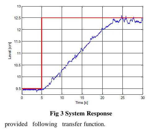
3.2 System Identification
In this section, nonlinear system model described with (9), will be approximated by the integrator and time
delay model.
In order to identify the tank model, step of maximum pump voltage was applied until the water level reached
303 |
P a g e
Fig 3 System Response
Identification process provided following transfer function.
G
ob(s) =
0.1553
𝑠
. 𝑒
−0.19𝑠
(10)
The transfer function of approximated system was used for simulation and tuning of PID and fuzzy
controller inside Matlab/Simulink program package.
IV. CONTROLLER IMPLEMENTATION
4.1 PID Controller Implementation
The design of PID controller based on transfer function and approximate model was done using
Matlab/Simulink. Control parameters (gain/proportional band, integral gain/reset, derivative gain/rate) were
adjusted to their optimum values for the desired control response (reaching the operating point of 12.5 cm) using
Ziegler-Nichols Method or auto tuning method. Simulink model shown on Fig. 4 was used for testing PID
controller performance by Z-N and auto tuning method.
304 |
P a g e
4.2 FUZZY Controller Implementation
Two Sugeno fuzzy controllers were designed based on mathematical model and approximate model was done
using Matlab/Simulink. One input Simulink model shown on Fig.5 was used for testing fuzzy controller
performance by FIS
Fig 5. One Input Simulink Model Used for Fuzzy Controller Testing
Two input Simulink model shown on fig 6
Fig 6. Two Input Simulink Model Used for Fuzzy Controller Testing
Since the tank system is nonlinear and water drainage is correlated with water level, two possible inputs for
fuzzy controller can be taken into account – error and current water height. In order to analyze the influence of
using measured water level as controller input, two types of fuzzy controller were implemented
1. One input fuzzy controller with error as input
2. Two inputs fuzzy controller with error and current water height as inputs,
The Sugeno model was used, since it is computationally efficient and works well with optimization and adaptive
techniques. This makes it popular for control problems, in particular for dynamic nonlinear systems.Properties
305 |
P a g e
Table i. Fis (Fuzzy Inference System) Parameters
FIS type Sugeno
AND method Prod
OR method Max
Defuzzyfication wtaver
In case of one input fuzzy controller, the error is calculated by taking the difference between referent
and current water level. Chosen error memberships functions are shown on Fig. 7.
Fig 7. Membership Functions of One Input Fuzzy Controller
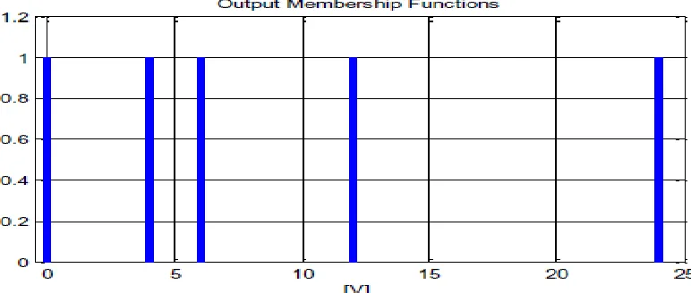
Output Membership functions represent voltage value.Output values are: 0, 4, 6, 12 and 24. Output MFs are
shown on Fig. 8.
Fig 8. Output Membership Functions of One Input Fuzzy Controller
The final output of the system is the weighted average of all rule outputs, computed as
𝐹𝐼𝑁𝐴𝐿 𝑂𝑈𝑇𝑃𝑈𝑇 = 𝑁𝑖=1𝑊𝑖 𝑍𝑖
𝑊𝑖 𝑁
𝑖=1 (10)
where N is the number of rules . In this case the number
306 |
P a g e
Table II. Rule Base for One Input Fuzzy Controller
If e is VN Output voltage is 0V
If e is N Output voltage is 4V
If e is O Output voltage is 6V
If e is P Output voltage is 12V
If e is VP Output voltage is 24V
Labels in Table II and Figure 7 are as follows: VN=Very Negative; N=Negative; 0=Small; P=Positive;
VP=Very Positive.
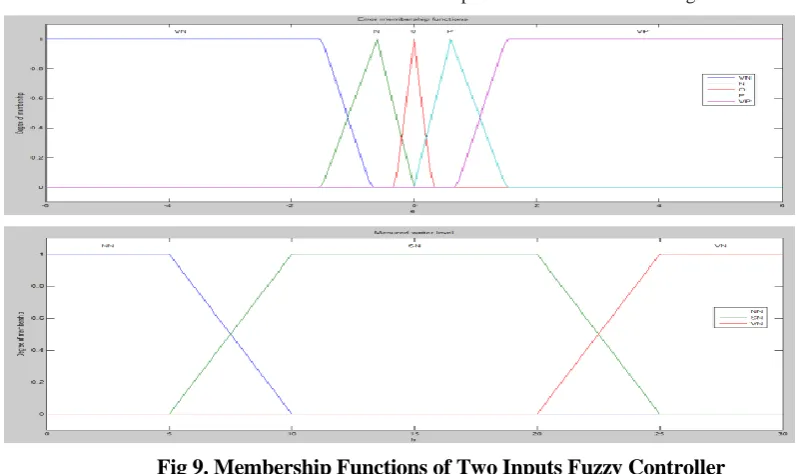
Inputs for two inputs fuzzy controller are current water level and error, calculated as a difference
between referent and current water level. Chosen memberships functions are shown on Fig. 9.
Fig 9. Membership Functions of Two Inputs Fuzzy Controller
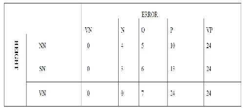
Output membership functions represent voltage value and they are shown on Fig. 10. Output values are: 0, 3, 4, 5,
6, 7, 10, 12, 13 and 24.
307 |
P a g e
The final output of the system is represented with weighted average of outputs of all rules, computed as in
equation (11). In this case the number of rules N is 11. Rule mapping is shown in Table III.
Table III. Rule Mapping For Two Inputs Fuzzy Controller
Labels in Table III. and Figure 9 are as follows: VN=Very Negative; N=Negative; 0=Small; P=Positive;
VP=Very Positive, NN=Low Height, SN=Medium Height, VN=High Height.
V. GRAPHICAL USER INTERFACE
Controllers were first designed using Matlab and tested using Simulink model, based on mathematical model
of tank. Functions that represent controllers were then created in programming language C. For more user-
friendly usage of these functions, GUI application was created. Simple GUI is designed using LABVIEW for
Friendly laptop. The GUI application is shown on Figure 11.
All control and measured data is collected and placed into files. Change of controllers type and set level is
308 |
P a g e
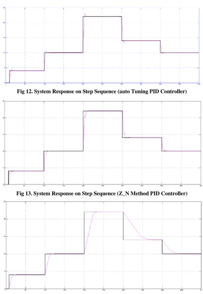
VI. SIMULATION RESULTS
Fig 12. System Response on Step Sequence (auto Tuning PID Controller)
Fig 13. System Response on Step Sequence (Z_N Method PID Controller)
309 |
P a g e
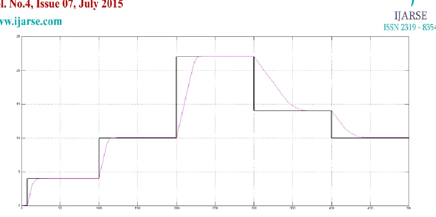
Fig 15. System Response on Step Sequence (Two Input Fuzzy Controller)
Based on experimental results, the control error and steady state error for both fuzzy controllers were
smaller, compared to PID controller. The fuzzy controllers provide better results on wider ranges of water level
set points. The two input fuzzy controller did not provide significant improvements compared to one input
fuzzy controller, although some improvements were achieved in terms of amplitude of oscillations around
stationary states.
VII. CONCLUSION
By implementing fuzzy and PID controllers for water level control, in form of application for Friendly ARM
embedded Computer (PC), user-friendly solution was offered. This solution can be used separately or as a part
of already existing control system. The use of fuzzy controller is fully justified by experimental results due to
nonlinearity of tank model.
REFERENCES
[1]. S. M. Shariar Kabir Khan ”design and implementation of a neural control system and performance
characterization with pid controller for water level control” International Journal of Artificial Intelligence &
Applications (IJAIA), Vol.2, No.2, April 2011,
[2]. Farhad Aslam “an implementation and comparative analysis of pid controller and their auto tuning
method for three tank liquid level control” International Journal of Computer Applications (0975 –
8887)Volume 21– No.8, May 2011,
[3]. Bijay Kumar “optimization of pid controller for liquid level tank system using intelligent techniques”
Canadian Journal on Electrical and Electronics Engineering Vol. 2, No. 11, November 2011
[4]. Senka Krivić, Muhidin Hujdur “design and implementation of fuzzy controller on embedded computer for
water level control“ MIPRO 2012, May 21-25,2012, Opatija, Croatiaa
Books
[5]. “MATLAB documentation,” Mathworks (www.mathworks.com)
310 |
P a g e
[7]. Daniel Wu, Fakhreddine Karray and Insop Song, “Water Level Control by Fuzzy Logic and Neural
Networks,” Unpublished.
[8]. Passino, K.M. & Yurkovich, S., “Fuzzy Control”, Addison Wesley, Menlo Park, 1998