R E S E A R C H
Open Access
A low-latency communication protocol
for target tracking in wireless sensor networks
Thu Ngo-Quynh
1*, Vinh Tran-Quang
2and Quan Nguyen-Trung
1Abstract
Target tracking applications in wireless sensor networks need to achieve energy efficiency, tracking accuracy, and certain real-time constraints in response to fast-moving targets. From a layer view, an energy-efficient cross-layer communication protocol that consists of a medium access control layer and network routing layer is necessary for joint optimization. Due to the interference and contention over the wireless medium, the limited resources of battery-operated sensor nodes, and the dynamic topology of large-scale networks, this cross-layer design becomes a challenging task. In this research, we exploit a cluster routing algorithm over large-scale networks and propose a low-duty-cycle medium access control (MAC) algorithm to reduce collision, idle-listening, and overhearing. In addition, our work focuses on the joint optimization of routing and a MAC strategy for achieving a good trade-off between low delay, energy efficiency, and tracking accuracy. To deploy this protocol in a real tracking application, we also propose a clustering synchronization procedure that does not require distributing the global timing information over the complete network to achieve network-wide time synchronization. An analytical model and extensive simulations are proposed to evaluate and compare the performance of our work with existing protocols. Simulation and analysis results show that our approach achieves better communication delay and thus better tracking error while maintaining reasonable energy consumption compared to other cases.
Keywords: Energy efficiency, Target tracking, Low latency, Synchronization, Communication protocol, Wireless sensor networks
1 Introduction
Recent developments in sensor techniques have made wireless sensor networks (WSNs) available to many appli-cation domains. Most of these appliappli-cations, such as bat-tlefield surveillance and target tracking, address various types of real-time constraints in response to the physi-cal world. For example, surveillance may require a sensor node to detect and classify a fast-moving target within 1 s before it moves out of the sensing range. Compared with the traditional distributed systems, achieving a low-latency guarantee for sensor networks is more challenging due to the following reasons. First, although the real-time performance is a key concern, it should be compatible with many other critical issues, such asenergy efficiency due to the limited power of sensor nodes. For example, it is not efficient to activate the sensors all the time for only
*Correspondence: [email protected]; [email protected] 1School of Information and Communication Technology, Hanoi University of Science and Technology, Hanoi, Vietnam
Full list of author information is available at the end of the article
the benefit of a fast response. This naive approach severely reduces system lifetime. Second, a large-scale network of unreliable wireless links makes thetracking accuracy of a target not quite suitable for low-delay detection. Thus, the two most important objectives of tracking problems in WSNs are low delayand energy efficiency associated withtracking accuracy, which cannot be met concurrently. Therefore, the design of a WSN-based tracking system requires a trade-off between these considerations.
To provide a real-time guarantee, the authors in [1] present an analysis of end-to-end delay by giving a brief overview of tracking operations. Normally, after a target enters the area, nodes nearby are awakened to form a cluster to deliver aggregated reports to the base station (BS). More specifically, the end-to-end delay contains the following main phases. (1) Initial delay: Initial delay is the time required for the first node to start to sense the incoming target and confirm the detection. (2)Wake-up delay: After the initial delay, a cluster is formed to pass
aggregated reports to the BS. To select a cluster with a reasonable size, nodes need to be awakened. The wake-up delay is the time required for an awakened node to wake up other sleeping nodes. (3)Aggregation delay: Each cluster is represented by a leader (called the cluster head— CH), which is responsible for collecting reports from cluster members. The CH, in turn, periodically trans-mits this report to the BS after the number of member reports exceeds a certain threshold. Aggregation delay is the time required to collect and process the detec-tion reports from the member nodes. (4)Multi-hop delay: After cluster aggregation, the transmission from the CH to the BS causes a multi-hop transmission latency.
Among these delay components, the initial delay that consists of the hardware response, discrete sampling, etc. depends on the hardware structure of the sensor nodes, while three other elements (wake-up, aggregation, and multi-hop) depend mainly on the communication proto-col implemented in the tracking system. From a layered view, these three latencies rely on the following compo-nents of the communication protocol. (1)Medium access control: The real-time property of a system depends on the effectiveness of the low-level medium access control (MAC) layer that is responsible for sharing the unreliable wireless medium. It plays a key role in determining the channel access delay and, thus, should provide a certain single-hop transmission timeguarantee. (2) In addition, it has been observed that low-power sensors consume a sig-nificant amount of energy while idly listening in addition to the energy consumed during transmission and recep-tion [2]. By controlling the fracrecep-tion of time that sensor nodes are ACTIVE/INACTIVE, energy can be conserved. This technique is called a duty-cycle. However, duty-cycling the radio transceiver leads directly to the increase of the wake-up latency. (3) Even if a certain deadline can be provided in the MAC layer, the real-time property can still not be met if there is no guarantee in thenetwork rout-ing layer. The report of a tracked target’s position from the CH transmitted to the BS over a large dynamic network should be bound by a certainmulti-hop transmission time. To guarantee low delay and improve energy efficiency for target tracking, it is important that all of these com-munication components (low-duty-cycle MAC and rout-ing) in the protocol stack be optimized. There is some previous work in this area [1, 3–10].However, this pre-vious work for target tracking application almost exclu-sively focuses on separate components, and the issue of low latency is not fully solved nor is the trade-off between latency and energy efficiency sufficiently and explicitly addressed. In other words, a complete communication scheme based on cross-layer interaction providing energy efficiency and low delay for target tracking is still an open research area although the use of cross-layer techniques in WSN can help to achieve different objectives. Due to
the interference and contention over the wireless medium, the limited resources of battery-operated sensor nodes, and the dynamic topology of large-scale networks, this cross-layer design is a challenging task. In this research, we exploit a cross-layer interaction involvingcluster rout-ing algorithm over large-scale networks and propose a low-duty-cycle MAC algorithm to reduce collision, idle-listening, and overhearing. In addition, our work focuses on the joint optimization of routing and MAC strategies to achieve a good trade-off between low delay, energy efficiency, and tracking accuracy.
Furthermore, the operation of a target tracking appli-cation often requires precise mapping of gathered sensor data with the time of the tracked target. To implement this application, the sensor nodes in the network need to have a common notion of time. Because the local clocks of the nodes operate independently and probably inac-curately [11], they need to be time-synchronized on a regular basis. Several time synchronization schemes have been extended for WSNs [12], taking into account some of the well-known constraints of WSNs. Normally, these schemes distribute global timing information over the entire network to achieve network-wide synchronization by using broadcast communication, but these solutions face severe challenges for target tracking. To overcome this problem in our cross-layer architecture, our cluster routing protocol is associated with acluster working-cycle synchronization procedure that needs only to maintain the synchronized working cycles of nodes only within the clusters. This procedure helps to achieve precise mapping of gathered sensor data with the time of tracked target without implementing a network-wide time synchroniza-tion protocol. The contribusynchroniza-tions of our work are described as follows:
(1) A new communication protocol CSP (Cluster-short Strobes-communication Protocol) consists of:
• A cluster-based routing algorithm that reduces and balances the number of packets involved in communication. Thus, it minimizes the processing time (for searching the next-hop node towards the BS), energy consumed, and load differentiation between nodes. For this reason, this new approach decreases the multi-hop transmission time significantly compared to others of the same category while maintaining reasonable energy consumption. • A new low-duty-cycle MAC protocol: The data
leads to the simple design of the CSP
low-duty-cycle MAC protocol: an unbeaconed Carrier Sense Multiple Access with Collision Avoidance (CSMA/CA) without Request to Send/Clear to Send (RTS/CTS) associated with a short-preamble approach for waking up other nodes. These two main design features of CSP’s low-duty-cycle MAC protocol help to avoid inefficient energy consumption and to minimize wake-up delay and also single-hop transmission delay.
• A new cluster working-cycle synchronization procedure: the design of routing and
low-duty-cycle strategies of the CSP leads to high structured traffic within clusters and from the CH towards the BS. In addition, the unbeaconed unslotted CSMA/CA algorithm associated with the low-duty-cycle scheme will cause a multi-hop asynchronous process of data transfer from the CH to the BS. Therefore, it is unnecessary to implement a complicated global timing procedure to achieve network-wide time synchronization. CSP, however, requires that the target distance estimation process realized by sensors be taken within a very short time interval to reduce “drifted” measurements due to target movements. To overcome this problem, we adopt a simple algorithm that maintains synchronization of working-cycles of nodes in a cluster without synchronizing the nodes’ clocks. (2) We also present an analysis of delay produced by the
CSP and compare to the other approaches of the same category (CSP using B-MAC [13] as an alternative low-duty-cycle algorithm and the CSP using Adaptive Routing Protocol with Energy Efficiency and Event Clustering for Wireless Sensor Networks (ARPEES) [14] as a routing strategy). The results from this analysis confirm that our CSP protocol produces the smallest delay among these schemes.
(3) The performance of this communication protocol in terms of energy consumption, tracking delay, and trajectory accuracy is evaluated and compared with other similar protocols through simulation. The simulation results show that out new method achieves better communication delay and thus better tracking accuracy while maintaining reasonable energy consumption.
The remainder of the paper is organized as follows. Section 2 discusses the related work. Section 3 describes the system model. Section 4 presents the operation of the CSP protocol. Section 5 analyzes the delay produced by
the CSP and compares it to others of the same category. Section 6 evaluates the performance of these commu-nication protocols. The conclusion and future work are discussed in the last section.
2 Related work
Recently, communication protocols designed for tracking applications have almost exclusively focused on separate components (low-duty-cycle MAC and routing schemes) to provide energy efficiency.To the best of our knowledge, there are only a few complete communication schemes in the area that consider the importance of low latency asso-ciated with energy efficiency and tracking accuracy as the main design goals. In addition, time synchronization for target tracking is also rarely investigated.
EDAL [15] is an energy-efficient and delay-aware com-munication protocol that consists of a routing strategy associated with a compressing sensing algorithm. How-ever, without low-duty-cycling mechanism and synchro-nization, it is difficult to achieve energy efficiency for uncompleted communication protocol EDA. RTSE [16] is a communication protocol that consists of data report and task execution for providing good performance by making trade-offs among delay, energy efficiency, and reli-ability when considering the characteristics of sensors and actuators, respectively. RTSE utilizes cluster-based rout-ing strategy, and nodes are supposed to be synchronized using existed time synchronization schemes. The design goal of RTSE is similar to our work (energy efficiency, delay...), and RTSE also implements cluster-based routing schemes but RTSE has two disadvantages: it is difficult to implement RTSE for target tracking application in a network with hundreds synchronized nodes and without duty-cycling MAC, energy efficiency is hard to achieved in RTSE.
difficult to exploit in a large network of hundreds of nodes. MCTA conserves energy by letting only a minimum num-ber of sensor nodes participate in communication by using the minimal tracking area based on the vehicular kinematics. Both ELS and MCTA are not concentrated on the design of low latency. Finally, t-tracking [17] is an interesting solution that achieves high tracking quality and energy efficiency. Consisting of a prediction scheme associated with duty-cycling and routing algorithms, t-tracking provides high quality t-tracking by utilizing mobile nodes and mobile sink.
Unlike classical approaches, Low Energy Self-Organizing Protocol (LESOP) [7] presents a cross-layer architecture of the application layer associated with the MAC layer and removes the transport and network lay-ers. All the radio packets are simply broadcasted to the source node neighborhood wirelessly. LESOP controls the trade-off between the only tracking error and network energy consumption while not investigating the impor-tance of system delay. Another cross-layer architecture [7] that consists of an extended 802.11 MAC and extended Dynamic Source Routing (DSR) algorithm. Unlike CSP, this cross-layer support does not consist of low-duty-cycle and synchronization schemes. Its main design feature is to reduce unnecessary routing maintenance. Therefore, this cross-layer DSR can not be implemented in the case of target tracking application. The multi-channel com-munication proposed in [18] is a special and interesting solution for reducing delay. The authors in this paper confirmed that decreased delay makes it possible to use higher sampling rates (or higher tracking performance) in network estimation applications and analyze only the dependencies between the communication protocol and the estimation parameters. The importance of delay required by certain real-time constraints in response to fast-moving targets is not evaluated.
Other solutions of routing protocol for target track-ing are described in [9, 10, 19–21], called MRP-NEP: Non-Equal-Probability Multicast Routing. Protocol, HCTT: Hybrid Cluster-Based Target Tracking Protocol, OCO: Optimized Communication and Organization, PES: Prediction-based Energy Saving Scheme, and CTT&MAV: Mobile Target Tracking Scheme. The main purpose of these novel routing protocols is to reduce communication overhead by using different routing strategies. MRN-NEP utilizes non-equal-probabilistic for-warding. Sensor nodes forward packets with a probability that is mainly determined by how much the node’s loca-tion deviates from the direcloca-tion of target moloca-tion. HCTC, a dynamic clustering routing, constructs on-demand clusters at boundary regions. Nodes from different static clusters that detect the target can temporarily share information, and the tracking task can be handed over smoothly from one static cluster to another. PES is based
on the fact that the movements of the tracked objects are sometimes predictable. This helps to reduce the trans-mission distance between the transmitter and receiver nodes and decrease the number of transmitted packets. OCO is an algorithm that ensures maximum accuracy of target tracking, efficient energy dissipation, and low computation overhead on the sensor nodes. CTT&MAV utilizes an energy-efficient clustering algorithm to form a Vonoroi-based diagram. However, these routing pro-tocols have not focused on the importance of system latency.
Without a low-duty-cycle MAC and routing in a com-munication protocol, it is difficult for all previous work to assure low latency associated with energy efficiency and tracking accuracy. VigilNet [1] is one of the very few real-world tracking systems that simultaneously addresses energy efficiency, end-to-end real-time tracking, and accuracy by implementing a complete communication protocol of B-MAC [13] (as a low-duty-cycle MAC) asso-ciated with a Voronoi diagram [22] (as a routing algo-rithm). This system divides end-to-end delay into multiple sub-deadlines, each guaranteed by one system compo-nent. Wake-up, aggregation, and multi-hop delays are controlled by the B-MAC protocol and Voronoi diagram (that requires the employment of multiple BSs). Thus, the hard real-time property of the system is guaranteed at the expense of numerous BSs and increased price. However, VigilNet has not been evaluated regarding the performance of end-to-end delay by considering critical parameters of the communication protocol. In addition, the long-preamble approach of B-MAC still causes energy inefficiency and unnecessary delay compared to short-preamble approaches, especially when the hop count is high.
All these issues challenge us with the question: How can one design a delay communication protocol of low-duty-cycle MAC, routing, and synchronization schemes to provide good tracking accuracy while maintaining energy efficiency?
3 System model
3.1 Measuring model
3.2 Sensing and network model
The delay from the beginning of the target localization mission until the time the result is returned is called senseDelay. The time period between two consecutive sensing processes is calledsensePeriod. To track the posi-tion of a target precisely, we need several measurements that are taken in the same short time interval. Therefore, the sensing timers of sensor nodes need to be synchro-nized to provide enough measurements.
3.3 Physical model
In this research, a simplified model of the physical layer imitating a typical transceiver is used to analyze the energy consumption and delay. Transceivers switch among IDLE, RX, and TX modes. The remaining energy will be updated when switching modes or by a periodical timer. Power consumption is calculated as follows:
P=PRX∗tRX+PTX∗tTX+PIDLE∗tIDLE (1)
where PRX, PTX, and PIDLE are the amounts of power consumed per unit of time when the node is in the corre-sponding state.tRX, tTX, andtIDLEare the durations of the node being in the RX, TX, and IDLE states, respectively.
4 CSP communication protocol
4.1 CSP routing scheme
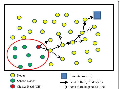
After a target enters the area, nodes near the target become activated, form a cluster, and select a cluster head (CH) that is responsible for receiving aggregating sensed data from cluster members. The CH selects a next-hop node by a broadcasting process and delivers the aggre-gated report to this node. This routing process (called multi-hop) is repeated until the BS is reached, causing a high number of packets to be involved in broadcasting communication (or high energy consumption) and high multi-hop delay. To overcome these problems, we pro-pose a cluster-based routing scheme (described in Fig. 1) to achieve low delay, energy efficiency, and good tracking accuracy. This scheme consists of three phases: initializa-tion, cluster formainitializa-tion, and relaying of data to the BS with the main design features:
• Reducing multi-hop delay and energy consumption: During the initializing phase, two relay and backup nodes (RN and BN) of each sensor are selected according to a relay node function. After the cluster formation phase, a CH is selected according to a cluster head function. The selected CH utilizes this RN or BN as a next-hop candidate during the data-relaying phase. Without the broadcasting process, the
Base Station (BS) Nodes
Sensed Nodes Cluster Head (CH)
Send to Relay Node (RN) Send to Backup Node (BN) Fig. 1Data transmission towards the BS and pseudocode of CSP routing
CH can reduce the processing time for searching for the next hop. Thus, it minimizes multi-hop delay and energy consumption significantly.
• Improving tracking accuracy: The data transmission from the CH to the RN or BN produces highly structured traffic of small packets towards the BS and between the only direct neighbors. This main design feature of the CSP cluster-based routing protocol reduces the packet overhearing and collision possibility and increases the tracking accuracy. In addition, each CH is always aware of its RN’s and BN’s energy levels and will replace them with new nodes if their energy falls below the critical level. Thus, it eliminates the chance that a node keeps sending data messages to its RN when the RN is already out of energy and hence improves the tracking accuracy.
4.2 Initializing phase
Each node in the network will choose a random time point in itsinitInterval(length of the initializing phase) to broadcast a RELAY_REQ{iD,Eres(i),(xi,yi)} packet containing its node identification iD, residual energy Eres(i), and location(xi,yi)to its neighbors. When nodei receives the packet, it chooses another random time point in the following interval of lengthwaitRelayInfo to send back a
RN and a BN based on following relay node function: The cosaj can be obtained by the following geometric calculation:
cosaj=
d(i,j)2+d(i,BS)2−d(j,BS)2
2di,j∗d(i,BS) (3)
According to this link cost function, two nodes that have relatively large residual energies, relatively small dis-tances to the BS and relatively small angle values (or straight paths towards the BS) are selected as the RN and BN. Actually, theinitIntervalmay not be identical for all nodes because the clocks of the nodes are not synchro-nized and it is hard to start the initializing phase in all nodes at the same time. However, as long as the initIn-tervalis much longer than the startup time of the entire network, the initializing phase will provide an efficient routing topology.
4.3 Cluster forming
When a target enters the area, the measured signal of sensors exceeds the predefined threshold, and it will set a timer that has a duration of collectInterval with col-lectInterval<sensePeriod. This timer defines an interval for collecting measurements of neighbor nodes. At this time, a set of the nodes detecting the target forms a cluster and synchronizes their sensing cycles (described in the following section). After realizing this synchro-nization algorithm, the working cycles of the nodes are constructed by predefined consecutive working intervals with a fixed length. Therefore, the nodes in a synchro-nized cluster have synchrosynchro-nized working cycles. Each nodeithen selects a random point withincollectInterval to broadcast aMEASUREMENT{(xi,yi),˜ri,Eres(i)}packet containing its coordinates, the distance from it to the tar-getr˜i and its current remaining energy. At the end of its collectInterval, each node will verify the number of col-lected measurements (including its own); if this number is at least three, the node checks the following cluster head function:
The node then compares its own value to the others produced by the cluster head function; if its value is the largest, the node will promote itself to be the CH. At the end ofcollectInterval, the CH estimates the position of the target based on its collected measurements.
4.4 Relaying data to the BS
After the CH estimates the position of the target, it will relay these data to the BS by sending a packet to the RN or BN. More concretely, it creates aDATA_TO_BSpacket and sends it to its RN and then sets a timer waitingRe-layInfo to wait for ENERGY_INFO{Eres(RN)} from the RN. When a node receives aDATA_TO_BS,it checks its remaining energy and sends back this information to the CH in anENERGY_INFOpacket. At the end of the wait-ingRelayInfotimer, the CH performs the following route maintenance activities:
• If the CH receives theENERGY_INFO packet, it updates the energy information of its RN. If the remaining energy of the RN is less than the remaining energy of the BN by a predefined amount
(switchingEnergy), the CH will switch the BN to the RN and the old RN to the BN.
• If the CH cannot receive theENERGY_INFO packet, it discards the current RN and chooses the BN as the new RN.
• If both the BN and RN have remaining energies lower than a predefined threshold or experience an
incident, the CH will request a new RN and BN the next time it needs to relay a packet.
After receiving the DATA_TO_BS packet, the RN, in turn, is served as the next CH and continues to relay this packet to its own RN. This process is repeated until reaching the BS.
4.5 CSP low-duty-cycle MAC protocol
The CSP low-duty cycle MAC protocol is designed to provide low delay, energy efficiency, and good tracking accuracy. As described in the previous section, the data transmission from the CH to the RN or the BN of the CSP cluster-based routing scheme leads to highly struc-tured communication: towards the BS and only between direct neighbors. In addition, typical packets are small (approximately 100 bytes) because the in-network pro-cessing allows for reporting concise information instead of raw sensor readings. This traffic feature reduces the num-ber of overhearing packets and the possibility of collision (and also tracking errors). Thus, we adopt the contention-based MAC protocol without the RTS/CTS mechanism and implement a simple back-off algorithm of unbea-coned and unslotted CSMA/CA. To minimize delay, CSP also implements a short strobe approach for waking up other nodes (based on the idea of X-MAC [23]). In con-clusion, the CSP low-duty-cycle MAC protocol holds the following features with two working states: ACTIVE and INACTIVE.
Algorithm 1 Initialization Phase: Selecting the RN and BN
Input: Knowing the position (xi,yi) of node i and the measuring distanced(i,BS)
Output: RN and BN 1: RN← ∅, BN← ∅ 2: ateach sensorido
3: athi∈[0,initInterval-waitRelayInfo)do 4: BroadcastRELAY_REQ{iD,Eres(i),(xi,yi)} 5: end
6: athi+waitRelayInfodo
7: FRN(j)=Eres(j)∗d(j1,BS)∗cosaj
8: ifMaxFRN(m)andSecondmaxFRN(n)then 9: RN←mandBN←n
10: end if 11: end
12: ifreceivingRELAY_REQand
currentTime∈[0,initInterval-waitRelayInfo)
then
13: atrandom timeki∈[currentTime,
currentTime+waitRelayInfo)]do
14: broadcastRELAY_INFO
15: end
16: end if
17: end
Algorithm 2Cluster formation phase: Selection of the CH
Input: measurement from sensoriof the parameter˜ri
Output: tracking cluster C and the Cluster Head CH 1: C← ∅, CH← ∅, timer←collectInterval 2: ateach sensorido
3: calculater˜i
4: ifIi≥thresholdthen 5: C← {i}
6: broadcastMEASUREMENT{xi,yi,˜ri, Eres(i)} 7: iftimer=0then
8: calculateFCH(i)= Eresr˜i(i) 9: ifMaxFCH(i)then
10: CH←i
11: end if
12: end if
13: end if
14: end
mode in transmission), and the node can send or receive packets with minimal delay. To conserve energy, if a node has no activities (e.g., sending or receiving packets) for a predefined time interval, it will automatically change its working state to INACTIVE; this interval can be con-figured appropriately with the traffic load of the specific application.
Algorithm 3Target Position estimation and Relaying of the data to the BS
Input: CH having aDATA_TO_BSpacket to send
Output: Receiving theDATA_TO_BSpacket at the BS 1: timer← ∅
2: CH calculatex=ftarget estimation{˜r1, ˜r2, ˜r3. . .} 3: CH produces theDATA_TO_BSpacket to send 4: repeat
5: CH sends theDATA_TO_BSpacket to the RN 6: timer←waitingRelayInfoi
7: receiving the ENERGY_INFO packet from the RN 8: iftimer← ∅thenupdateEres(RN)then
9: ifEres(RN)≤(Eres(BN)+switchingEnergy)then 10: TG←RN, RN←BN, BN←TG
11: end if 12: end if 13: CH ←RN
14: untilUntil reaching the BS
In the INACTIVE state, the radio transceiver is switched to IDLE mode, which has very low power consumption; however, the transceiver cannot transmit or receive pack-ets in this mode. To maintain connectivity with other nodes, a node in the INACTIVE state will periodically switch its transceiver to RX mode for a short interval. The interval in which the transceiver is switched to IDLE mode is calledsleepInterval, and the interval in which the transceiver is switched to RX mode is calledlistenInterval. listenIntervalenables the node to receive special control packets calledstrobes; therefore, strobes can be used by a node to wake up other nodes from the INACTIVE state.
When in the INACTIVE state, a node changes to the ACTIVE state in three cases:
• It receives strobe packets addressed to it (in the short interval, its transceiver is switched to RX mode). • The upper layer wants to send a packet.
• There is a demand from the upper layers to stay in the ACTIVE state for a specific amount of time or even forever (e.g., the BS does not need to ever be INACTIVE). In this case, the normal time-out for switching to the INACTIVE state is overridden. This feature helps to increase the availability of network nodes.
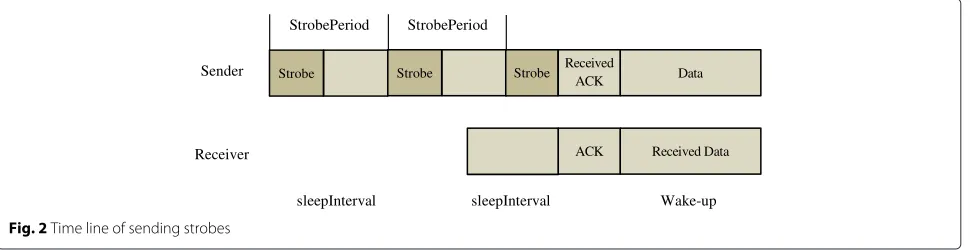
can receive an ACK back from the receiver if the receiver successfully received the strobe. When the sender receives an ACK packet from the receiver, it stops sending the strobe sequence and sends the main packet immediately (Fig. 2).This mechanism reduces the per-hop latency and unnecessary energy spent waiting and transmitting.
ThelistenIntervalof a node needs to be large enough so that a node can receives strobes from a sender. This time is calculated as follows:
listenInterval=2∗strobePeriod−preservedInterval (5)
The maximum number of strobes in a sequence is fixed and calculated as follows:
nStrobemax=
sleepInterval strobePeriod
(6)
After sending allnStrobemaxstrobe packets, the sender will send the main packet even if it does not receive any ACK. (In most cases, this mechanism can wake up the receiver and deliver the main packet successfully).
4.6 CSP cluster synchronization algorithm
Within a cluster, each node is responsible for estimating the distance from it to the target and sending this infor-mation to the CH. If the clocks of these nodes are unsyn-chronized, the measurements of sensors will be “drifted” because of the target movement. To overcome this prob-lem, we adopt a simple mechanism to synchronize the working cycles of nodes in a cluster. This mechanism is based on adjusting timers for triggering the sensing action of nodes at the same time by utilizing the broadcast nature of wireless communication and predicting the sensing cycles of nodes. It consists of two steps:synchronization during target detection and clusteringandsynchronization during target positioning at the CH and relaying data to the BS. After realizing this cluster synchronization algo-rithm, the working-cycles of nodes are constructed by pre-defined consecutive working intervals with fixed length. Therefore, nodes in a synchronized cluster have synchro-nized working cycles, and it is unnecessary to synchronize the clocks of nodes.
4.6.1 Synchronization during target detection and clustering
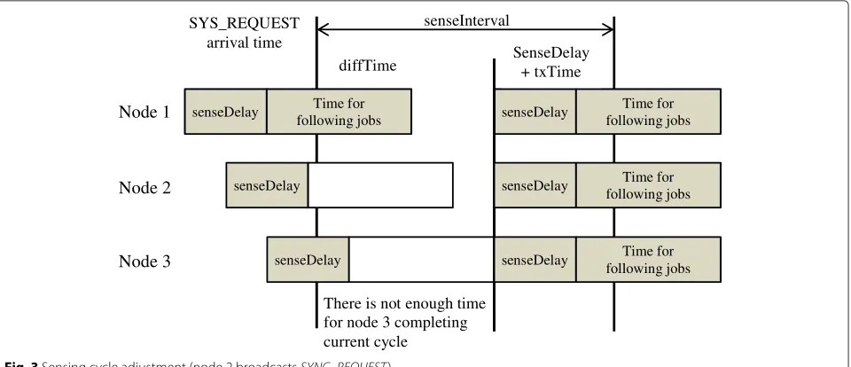
Initially, each node maintains its own sensing cycle and a SYNC flag set to FALSE. If a node detects the tar-get for the first time, it changes its SYNC flag from FALSE to TRUE and broadcasts a SYNC_REQUEST packet to adjacent nodes. Its neighbor nodes, after receiv-ing the SYNC_REQUEST packet, change their SYNC flag to TRUE and adjust their sensing cycles according to the cycle of the sender by calculating the following equation:
diffTime=sensePeriod−senseDelay−txTime (7)
where txTime is the calculated time for sending the SYNC_REQUEST packet. We can realize that the result of this equation (diffTime) is identical for all sensor nodes and can be calculated beforehand. In Fig. 3, node 2 broad-casts the SYNC_REQUEST packet. After receiving this packet, nodes 1 and 3 have to adjust their sensing cycles in two possible cases:
Case 1:Node 1 has completed its sensing action when receiving theSYNC_REQUESTpacket. To match its sens-ing cycle to the cycle of node 2, it calculatesdiffTimeand adjusts its timer for the next sensing action.
Case 2: Node 3 has not completed its sensing action when receiving theSYNC_REQUEST packet; it also cal-culatesdiffTimeand adjusts its timer for the next sensing cycle. However, in this case, the current cycle is shortened, and node 3 may not be able to complete the following steps. Therefore, node 3 discards the current sensing cycle and waits for the next cycle.
The SYNC flag of a node is reset to FALSE when the node cannot detect any target after receiving the sensing result from the sensor.
The synchronization step described previously pro-vides an initial synchronized group for a node when it newly detects a target. However, this procedure is not enough to maintain a good number of sensor nodes to assure good tracking accuracy. The second synchro-nization step led by the CH is realized to solve this problem.
Strobe Strobe Strobe Received
ACK Data
StrobePeriod StrobePeriod
Sender
ACK Received Data
Receiver
sleepInterval Wake-up sleepInterval
There is not enough time for node 3 completing current cycle
senseDelay
Node 1 following jobs Time for senseDelay Time for
following jobs
senseInterval SYS_REQUEST
arrival time
diffTime SenseDelay + txTime
senseDelay senseDelay Time for
following jobs
senseDelay senseDelay Time for
following jobs Node 2
Node 3
Fig. 3Sensing cycle adjustment (node 2 broadcastsSYNC_REQUEST)
4.6.2 Synchronization during target positioning at the CH and relaying of data to the BS
The last action of the CH in a sensing cycle is maintaining the synchronization of the cluster. For re-synchronizing nodes in a cluster with the CH, the CH broadcasts a CH_BEACON packet at a specific moment near the end of each sensing cycle (called chBeaconTime). Similar to the previous step, nodes receiving this beacon will adjust their sensing cycle with the CH by calculating diffTime according to the following equation:
diffTime=sensePeriod−chBeaconTime−txTime (8)
wheretxTimeis calculated depending on the network con-figuration and may be optional. Because this beacon is broadcast at a moment near the end of a working cycle, the receiving nodes will cancel their remaining jobs of the current cycle if they have not finished (e.g., broadcast measurement, collecting measurements from others) and consider it to be the end of the cycle just like the CH. For example, if thesensePeriodis 0.5 s,CH_BEACON is broadcasted at 0.4 s into the cycle, andtxTimeis 0.001 s. If a node receives aCH_BEACONfrom the CH, whatever point in the current cycle it is, it will cancel its jobs of the current cycle and plan its next sensing action at 0.099 s after the current time.
5 Delay estimation
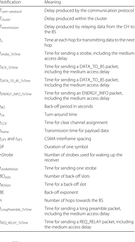
In this section, we evaluate the communication delay pro-duced by CSP and utilize the denotations described in Table 1 . These delay components can be calculated as:
Tcom−protocol =Tcluster+Ttransmission (9)
whereTcluster is the time produced after the sensing sig-nal until the end of the data exchange within the cluster.
According to the routing strategy described before, this duration is constant and equals tocollectInterval. We can have
Tcluster=collectInterval (10)
andTtransmissionis the delay due to data transmission from the CH to the BS. This delay can be calculated as
Ttransmission= n
i=1
tri (11)
wheretriis the delay produced at each hop for transmit-ting data to the next hop and n is the number of hops from the CH towards the BS. We now evaluate tri for different communication protocols: CSP, CSP using B-MAC as an alternative low-duty-cycle scheme, and CSP using ARPEES [14] as an alternative cluster-based routing scheme. For simplicity, we assume here a perfect channel with no loss due to collision. In addition, no packets are lost due to buffer overflow at either sender or receiver.
5.1 CSP
Table 1Meaning of delay notifications
Notification Meaning
Tcom−protocol Delay produced by the communication protocol
Tcluster Delay produced within the cluster
Ttransmission Delay produced by relaying data from the CH to
the BS
tri Time at each hop for transmitting data to the next hop
tstrobe_TxTime Time for sending a strobe, including the medium
access delay
tACK_TxTime Time for sending a DATA_TO_BS packet,
including the medium access delay
tDATA_TO_BS_TxTime Time for sending a DATA_TO_BS packet,
including the medium access delay
tENERGY_INFO_TxTime Time for sending an ENERGY_INFO packet,
including the medium access delay
tBO Back-off period in seconds
tTA Turn-around time
tCCA Time for clear channel assignment
tframe Transmission time for payload data
tLIFSandtSIFS CSMA interframe spacing
SP Duration of one symbol
nStrobe Number of strobes used for waking up the receiver
tstrobePeriod Time for sending one strobe
BOslots Number of back-off slots
tBOslots Time for a back-off slot
BE Back-off exponent
n Number of hops towards the BS
tLongPreamble_TxTime Time for sending a long preamble packet,
including the medium access delay
tREQ_RELAY_TxTime Time for sending a REQ_RELAY packet, including
the medium access delay
The back-off period is expressed as follows:
TBO=BOslots∗tBO slots (17)
The number of back-off slots is a uniform random num-ber in the interval(0, 2BE −1)where BE is the back-off exponent, which has a minimum of 3. As we only assume one CH and a perfect channel, the BE will not change. In this case, the number of back-off slots can be represented as the mean of the interval(0, 2BE−1)/2 or 3.5. Due to the characteristics of CSP, the transmission between the only CH and the RN is free, and the packet is transmitted after only one instance of back-off and CCA. In addition, we have the following relations in 802.15.4 where SP is the duration of one symbol [24]:
tBO = 3.5∗20∗SP
and the duration time for sending a packet is calculated as follows:
tframe(packet)=
packet size
rate (19)
With the different sizes of different packets given in Table 2 (strobe, ACK, DATA_TO_BS, and ENERGY_INFO) and the frequency band 2.4–2.4835 GHz with a symbol rate of 62.5 Kbaudps and bit rate of 250 Kbps (please refer to [24] for more information), Eqs. (13, 14, 15, 16) can be calculated, and the sum of all these equations is equal to 0.01232 s. Based on that, the average communication delay of our system for a wireless medium is
tCSPri =(nStrobe−1)∗strobePeriod
+0.01232s (20)
and the total communication delay produced by CSP is
tCSPcom_protocol =collectInterval+
+
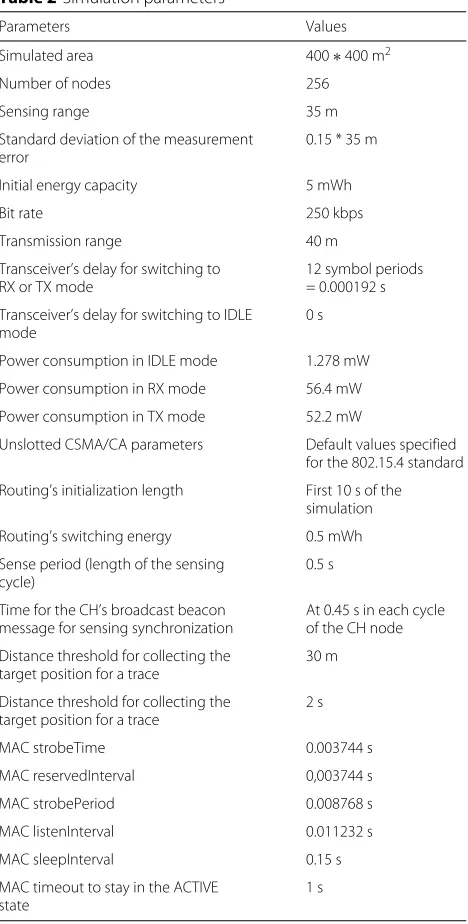
Table 2Simulation parameters
Parameters Values
Simulated area 400∗400 m2
Number of nodes 256
Sensing range 35 m
Standard deviation of the measurement error
0.15 * 35 m
Initial energy capacity 5 mWh
Bit rate 250 kbps
Transmission range 40 m
Transceiver’s delay for switching to RX or TX mode
12 symbol periods = 0.000192 s
Transceiver’s delay for switching to IDLE mode
0 s
Power consumption in IDLE mode 1.278 mW
Power consumption in RX mode 56.4 mW
Power consumption in TX mode 52.2 mW
Unslotted CSMA/CA parameters Default values specified for the 802.15.4 standard
Routing’s initialization length First 10 s of the simulation
Routing’s switching energy 0.5 mWh
Sense period (length of the sensing cycle)
0.5 s
Time for the CH’s broadcast beacon message for sensing synchronization
At 0.45 s in each cycle of the CH node
Distance threshold for collecting the target position for a trace
30 m
Distance threshold for collecting the target position for a trace
2 s
MAC timeout to stay in the ACTIVE state
1 s
(equal to 3). Similar to the previous case, we receive the following results:
tcom_protocol≤collectInterval+
+n(sleepInterval+0.075664)(s) (24)
From the above equation, we realize that the total com-munication delay produced by CSP depends on collectIn-terval,sleepInterval, and also the number of hops towards the BS. Because the collectInterval duration is constant and the number of hops towards the BS is a dynamic variable that cannot be controlled, we can adjust only sleepIntervalto control the total communication delay of our communication protocol.
5.2 CSP using B-MAC as an alternative low-duty-cycle scheme
In this case, trBi−MAC is also caused by transmitting DATA_TO_BS from the CH to the RN, but the B-MAC protocol produces different latency for the media access delay. Similar to the previous section, this delay can be evaluated as follows:
Due to the routing strategy of CSP, the CH needs to wake up only the RN to transmit aDATA_TO_BSpacket. This characteristic helps to reduce the medium accessing time of a long preamble packet, or we can assume, in the ideal case, that a long preamble packet can successfully access the wireless medium after only one back-off. In this case, each hop delay produced by B-MAC is higher due to the large size of the long-preamble approach compared to the CSP protocol.
5.3 CSP using the ARPEES protocol as an alternative routing strategy
The cluster delay produced by ARPEES is similar to that of the CSP protocol. We investigate now the transmis-sion delay produced at each hop by ARPEES. To search for the next relay node, the ARPEES protocol broadcasts a REQ_RELAY message, waits to receive theACK_RELAY from all its neighbors, and then evaluates its relay node function. Thus, different neighbors of the CH attempt to access the wireless medium to send their ACK messages. This feature leads to a significant increase of the delay produced at each hop compared to the CSP protocol.
tARPEESri =tREQ_RELAY_TxTime +tACK_TxTime +tDATA_TO_BS_TxTime
6 Performance evaluation
The main goal of the experimentation described in this article is to measure and compare the energy consump-tion, communication delay, and tracking accuracy of the proposed communication protocol as a function of vary-ing the input parameters.
6.1 Experimental setups
We have developed an extensive computer simulation, implemented in the OMNET++ simulator [25], to eval-uate performance of the three cases: CSP, CSP using B-MAC, and CSP using ARPEES. A total of 256 sensor nodes are evenly distributed over an area of(400×400)m2. A BS is positioned at the coordinates of(200, 400)m. One tar-get moves in the network area after 10 s from the start of the simulation; the target’s speed ranges from 6 to 12 m/s. The sensing range of the target is 35 m, and the measure-ment error has a standard distribution with an expected value of 0 m and a standard deviation of 15 % of the sens-ing range. Each network node has a transmission range of 40 m (again, this representation is for simplicity). Sensor nodes work in sensing cycles with a length of 0.5 s. At the start of the simulation, every sensor node is provided with an identical amount of energy, 5 mWh.
6.2 Result analyses
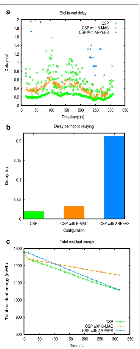
In order to assure real-time property, the detection, local-ization, and report of target position need to be com-pleted within each sampling interval. In other words, the end-to-end delay needs to be smaller than the sampling interval that equals to 0.5 s in our simulation. We per-form experiments in three configurations (default CSP, CSP with B-MAC as duty-cycle scheme, and CSP with ARPEES as routing scheme) and plot variation of end-to-end delay, per hop delay, and total residual energy of these three cases in Figs. 4 and 5. The last figure (Fig. 6) presents tracking error and tracking trajectory. In each case, we simulate and select the simulation with the best tracking quality, and these three best cases of three configurations are utilized later for performance comparison.
In Fig. 4, we realize that CSP achieves the best end-to-end delay performance where most of the packets arrive at the BS with end-to-end delay lower than 0.5 s. In addi-tion, a small number of packets of CSP have high delay because the target moves to an area where sensor nodes have not been activated. When using B-MAC, end-to-end delay is higher but more stable compared to CSP. The last configuration, CSP using ARPEES causes the highest end-to-end delay. Unlike end-end-to-end delay, per-hop delay of the three cases varies differently: in CSP using B-MAC, packets have fixed per hop delay because of fixed size of long preamble, and therefore, the sum of per hop delay is stable and proportional to the number of hops towards BS.
a
b
c
a
b
c
Fig. 5 aEnd-to-end delay,bdelay per hop, andctotal residual energy of CSP according tosleepInterval
Note that in CSP using B-MAC, B-MAC works in heavy load by setting short checktime. In B-MAC [13], check-timeis the duration between two consecutive CCA and
a
b
c
Fig. 6 aEnd-to-end delay,bdelay per hop, andctotal residual energy of CSP according tosleepInterval
receive strobe at the end ofsleepInterval), per hop delay produced by CSP is dominated by a fullsleepInterval. In this worst case, default CSP works similarly as CSP using B-MAC and produces higher per hop delay because sleep-Interval is higher than checktime (Fig. 4). However, this per-hop delay of CSP is generally much smaller than the per hop delay of the worst case due to two reasons.
• Because of short preamble approach of CSP, the strobes train can be shortened by acknowledgment packets.
• CSP efficient routing algorithm creates stable routing path in which, nodes stays in ACTIVE state and can reply immediately to the first few strobes. Therefore, most per hop delay will be the best case.
With CSP using ARPEES routing scheme, the process of finding relay node is repeated at each relay hop and causes too much overheads associated with high usage of wire-less medium. After few hops, this process can cause delay higher than the period of traffic generation; therefore, congestion will occur.
We also track total energy of the network in the sim-ulation in Fig. 4. By using duty-cycle protocol, the sys-tem achieves better energy efficiency compared to no duty-cycle solution (CSP with ARPEES). In the first 10 s of our simulations (initial phase of default configura-tion and configuraconfigura-tion with B-MAC), the duty cycle is disabled for network initialization. During this interval, the power consumption is much higher than duty-cycle period. Result from this simulation shows that B-MAC has slightly better power consumption compared to two other cases. It is important to note that at any time, most of the nodes in network are in ACTIVE state and the total energy consumption of network is caused mainly by consumption of ACTIVE nodes. This consumption depends on the ratio of duration of transceiver in RX mode/duration of transceiver in IDLE mode. This ratio of CSP using B-MAC is very low because each node only needs to stay in RX mode to complete a CCA. In CSP, transceiver has to stay in RX mode to wait for a complete MAC packet. Therefore, the ratio of CSP using B-MAC is shorter than that of CSP.
As explained in Section 5, sleepInterval can be con-trolled in order to adjust the trade-off between communi-cation delay and energy consumption of CSP. We repeat experiments when changing the sleepInterval, and the results (Fig. 5) consistently prove that the longer sleep-Interval leads to the lower energy consumption and also to the higher delay. As stated above, increasing sleepIn-terval helps to decrease the ratioduration of transceiver in RX mode/duration of transceiver in IDLE modeand to reduce total power consumption. It is important to note that increasingsleepInterval does not influence the best case per hop delay, and it improves power consumption
in the expense of increasing delay slightly. In addition, the worst case end-to-end delay causes additional packet loss by congestion at newly formed clusters and relay paths. Packet loss may lead to degraded tracking quality. There-fore, adjustingsleepInterval for controlling total residual energy must also depend on traffic load and tracking quality requirement.
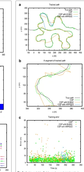
Finally, the target tracking trajectories and tracking error of CSP, CSP using B-MAC, and CSP using ARPEES are plotted in Fig. 6. As described in the previous section, the characteristic of the low delay of CSP leads to better tracking error or accuracy, especially when system works under high load (due to high sampling rate and dense node distribution). The results from Fig. 6 also prove that CSP achieves the best performance of tracking accuracy, compared to CSP using B-MAC and CSP using ARPEES. Thus, low delay plays an important role of a target tracking system for providing good tracking accuracy.
7 Conclusions
The design of a low delay communication protocol plays an important role in providing good tracking accuracy and energy efficiency for a target tracking system in WSNs. In this work, we present a new communication protocol, CSP, that consists of a routing strategy associated with a low-duty-cycle MAC, and we focus on the joint optimiza-tion of these schemes to achieve low delay, low tracking error, and low energy consumption. Unlike other tradi-tional tracking systems, CSP does not require global tim-ing to achieve network-wide synchronization of the clocks of nodes. The design of a routing strategy and a low-duty-cycle MAC protocol of CSP leads to a simple cluster synchronization algorithm for synchronizing the working cycles of the nodes within a cluster. We present an anal-ysis of the delay produced by CSP, CSP using B-MAC, and CSP using ARPEES and prove that CSP achieves the best delay performance. We also develop simulation experiments, and the results of such simulation show that CSP achieves the best delay performance, and thus the best tracking error, while maintaining reasonable energy consumption.
Competing interests
The authors declare that they have no competing interests.
Acknowledgements
This research is funded by the Vietnam National Foundation for Science and Technology Development (NAFOSTED) under grant number 102.04-2012.06.
Author details
1School of Information and Communication Technology, Hanoi University of Science and Technology, Hanoi, Vietnam.2School of Electronics and Telecommunications, Hanoi University of Science and Technology, Hanoi, Vietnam.
References
1. T He, S Krishnamurthy, L Luo, T Yan, L Gu, R Stoleru, G Zhou, Q Cao, P Vicaire, JA Stankovic, TF Abdelzaher, J Hui, B Krogh,VigilNet: An integrated sensor network system for energy-efficient surveillance,” ACM Trans. Sen. Netw, vol. 2, (2006), pp. 1–38
2. C Hsin, M Liu, inProceedings of the 3rd International Symposium on Information Processing in Sensor Networks,IPSN ’04. Network coverage using low duty-cycled sensors: random & coordinated sleep algorithms, (2004), pp. 433–442
3. NA Vasanthi, S Annadurai, An adaptive energy-efficient low latency sleep schedule for target tracking sensor networks. IJCSNS Int’l J. Comput. Sci. Netw. Secur.8(4), 548–554 (2008)
4. Y Wang, P Shi, K Li, Z Chen, An energy efficient medium access control protocol for target tracking based on dynamic convey tree collaboration in wireless sensor networks. Int’l J. Commun. Syst.25(9), 1139–1159 (2012) 5. M Li, Y Xiong, Y Cchen, H Si, A MAC protocol for target-tracking in wireless
sensor network. Chin. J. Electron.22(2) (2013)
6. J Jeong, T Hwang, T He, D Du, inINFOCOM 2007. MCTA: Target Tracking Algorithm Based on Minimal Contour in Wireless Sensor Networks, (2007), pp. 2371–2375
7. L Song, D Hatzinakos, A cross-layer architecture of wireless sensor networks for target tracking. IEEE/ACM Trans. Netw.15(1), 145–148 (2007) 8. N Chilamkurti, S Zeadally, A Vasilakos, V Sharma, Cross-layer support for
energy efficient routing in wireless sensor networks. J. Sensors.2009, 19 (2009)
9. B Diao, P Li, Z An, F Wang, Y Xu, in5th FTRA International Conference on Computer Science and its Applications (CSA-13). MRP-NEP: A
Non-equal-probability Multicast Routing Protocol for Target Tracking in Wireless Sensor Networks, (2013), pp. 201–208
10. Z Wang, W Lou, Z Wang, J Ma, H Chen,A Hybrid Cluster-Based Target Tracking Protocol for Wireless Sensor Networks, Article ID 494863, vol. 2013. (International Journal of Distributed Sensor Networks, 2013), p. 16. doi:10.1155/2013/494863
11. B Sundararaman, U Buy, A Kshemkalyani, Clock synchronization for wireless sensor networks: a survey. Ad Hoc Netw. (Elsevier).13, 281–323 (2005)
12. S Ganeriwal, R Kumar, M Srivastava, in1st International Conference on Embedded Networked Sensor Systems. Timing-sync protocol for sensor networks, (2003), pp. 138–149
13. J Polastre, J Hill, D C, inSecond ACM Conference on Embedded Networked Sensor Systems (SenSys). Versatile low power media access for wireless sensor networks, vol. 2nd (ACM Press, Baltimore, MD, USA, 2004), pp. 95–107
14. V Tran-Quang, T Miyoshi, Adaptive routing protocol with energy efficiency and event clustering for wireless sensor networks. IEICE Trans. Commun.E91-B(9), 2795–2805 (2008)
15. Y Yao, Q Cao, A Vasilakos, Edal: An energy-efficient, delay-aware, and lifetime-balancing data collection protocol for heterogeneous wireless sensor networks. Netw. IEEE/ACM Trans.23(3), 810–823 (2015) 16. Y Zeng, D Li, A Vasilakos, Real-time data report and task execution in
wireless sensor and actuator networks using self-aware mobile actuators. Comput. Commun.36(9), 988–997 (2013)
17. M Bhuiyan, G Wang, A Vasilakos, Local area prediction-based mobile target tracking in wireless sensor networks. Comput. IEEE Trans.64(7), 1968–1982 (2015)
18. J Nieminen, R Jantti, J Eriksson, inWireless Commun. and Networking Conf. (WCNC 2012). Performance of target tracking applications in
multi-channel wireless sensor networks (IEEE, 2012), pp. 1542–1547 19. S Phu-Manh-Tran, TA Yang, inProc. SIGCSE 2006. Evaluation of target
tracking in wireless sensor network, (2006), pp. 97–101
20. Y Xu, J Winter, WC Lee, inProc. IEEE. International Conference for Mobile Data Management. Prediction-based strategies for energy saving in object tracking sensor networks, (Berkeley, CA, 2004), pp. 346–357 21. J Chen, M Salim, M Matsumoto, A single mobile target tracking in
voronoid-based clustered wireless sensor networks. J. Inf. Process. Syst. 7(1), 17–28 (2011)
22. B A Okabe, K Boots, S Sugihara,Chiu, Spatial Tessellations: Concepts and Applications of Voronoi Diagrams. (Wiley, New York, 2000)
23. M Buettner, G Yee, E Anderson, R Han, inProc. of SenSys’ 06. X-MAC: a short preamble MAC protocol for duty-cycled wireless sensor networks, (2006), pp. 307–320
24. B Latré, Throughput and delay analysis of unslotted ieee 802.15. 4. J. Netw.1(1), 20–28 (2006)
25. A Varga. Omnet++: an objective modular network testbed in C++. in Version 3.3, retrieved from official website: https://omnetpp.org.
Submit your manuscript to a
journal and benefi t from:
7Convenient online submission
7Rigorous peer review
7Immediate publication on acceptance
7Open access: articles freely available online
7High visibility within the fi eld
7Retaining the copyright to your article