Reduced Latency Majority Logic Decoding for Error Detection
and Correction
D.K.Monisa1, N.Sathiya2
1
Department of Electronics and Communication Engineering, Mahendra Engineering College,
Namakkal, Tamilnadu, India
2
Department of Electronics and Communication Engineering, Mahendra Engineering College,
Namakkal, Tamilnadu, India
Abstract
In order to rectify the errors that occurs in a storage device, Majority Logic Decoding is used. In MLD, the number of iterations performed for Error Detection and Error Correction (ED & EC) is equal to the number of bits in the codeword. Thus, as the number of bits in the codeword increases, number of iterations increases accordingly. This means that the latency of MLD is high. This paper aims to reduce the latency of MLD. This can be achieved by means of Modified MLD (MMLD) and Modified MLD with Control (MMLDC). In MMLD, the number of iterations has been reduced to 7 and in MMLDC the number of iterations has been reduced to 3.Xilinx ISE 14.1 simulator is used to carry out the work.
Keywords: Majority Logic Decoding (MLD), Modified Majority Logic Decoding (MMLD) , Modified Majority Logic decoding with Control (MMLDC),Multiple Cell Upset(MCU),Difference Set Low Density Parity Check (DS-LDPC).
1. Introduction
Semiconductor memory is a storage element which stores binary 0 or 1. It is widely used in cellular phones, digital cameras, smart pads etc. As the size of the memory is reduced, multiple data bits are stored in a memory cell which results in Multiple Cell Upset (MCU).
The errors may occur in the data stored in memory due to MCU and Cell to Cell Interference. This type of error is called as soft error. In order to correct the errors that occur in the data stored, several ED & EC algorithms are used, such as LDPC Codes.
LDPC code is a Forward Error Correcting Code, introduced by Gallagar at MIT [1]. Since the
implementation of LDPC codes were difficult, it remained unnoticed for 35 years. Later on, LDPC codes were rediscovered at the time of the invention of Tanner Graph [2]. LDPC codes can be represented either in the form of matrix or graph. In LDPC, the percentage of number of zeros are greater than the percentage of number of one’s. Thus the power consumed by LDPC is less because of the reduced switching activity. This has made the LDPC codes very popular.
Hard Decision Algorithms such as Hamming code, Message –Passing, Bit-Flipping were proposed for the decoding of LDPC codes[3], [4], [5], [6], [7]. Hard Decision Algorithms is based on the binary values. Its performance is poor when compared to Soft- Decision Algorithms, but the complexity is high in Decision Algorithms. Some of the Soft-Decision Algorithms are Min-Sum Algorithm, a posteriori probability based algorithm (APP) [8], [9], [10].
To reduce the complexity of operations, MLD algorithm is used for decoding. One step MLD is implemented serially, but the latency is high[9]. In this paper, specific group of LDPC codes called as Difference Set LDPC (DS-LDPC)[10] is considered which is widely used in FM broadcasting systems. MLD is used for decoding DS-LDPC since the complexity is less. Number of iterations in MLD will be same as the size of the code word. The main target of this paper is to lower the decoding time (iterations) taken for the correction of error.
proposed method MMLDC, and Section 4 illustrates analysis of results of both the techniques.
2. Modified MLD
In MMLD, message bits are alone considered for error correction so that the number of iterations required for ED&EC is reduced to 7. In MMLD, the number of iterations required for ED&EC is equal to the length of the message bits. If the number of iterations gets reduced, then the power consumed by the system is also reduced.
Here, the parity bits are not considered for the process of error correction. A different set of parity check equations are chosen from the LDPC matrix H which is constructed by using Gauss-Jordan elimination. After the generation of codeword by the encoder, error detecting and correcting process will start.
In a 15 bit codeword which is generated by encoder, first 7 bits corresponds to message bits and the rest of them are parity bits. At the decoder, the codeword is loaded into 15 bit cyclic shift register. MMLD consists of four parts namely
1. a shift register (cyclic)
2. an array of XOR gates for checking the parity equations
3. a majority gate which is a carry circuit of a full adder and
4. an XOR gate which performs the error correction
MMLD consists of two steps, the first involves producing the result for check equations and in the second step, the majority value of the results obtained is determined. Check equations used in MMLD are
1. c(11) xor c(9) xor c(8) xor c(0) 2. c(13) xor c(12) xor c(4) xor c(0) 3. c(14) xor c(6) xor c(2) xor c(0) 4. c(7) xor c(3) xor c(1) xor c(0)
Cyclic shift register is stored with the input i.e., the received code word. Initially, first bit of the message is considered. Outcome of the four above mentioned check equations is calculated from the values in the shift register and is sent to the majority circuit. In the majority circuit, if the number of ‘1’s is greater than number of ‘0’s, output of the majority circuit will be ‘1’, otherwise it will be ‘0’.
It is the majority value of the output which determines the correctness of the each bit in the code
word. If the majority output is “1”, then one of the input of XOR gate will be ‘1’ (corresponding bit will be inverted), otherwise the input to the XOR gate will be ‘0’. When all the check equations output is zero, the codeword doesn’t have any flaws.
Fig.1. MMLD of DS-LDPC
Then, first bit of the message is shifted left arithmetically. This is repeated until all the message bits in the code word is checked. Since 7 message bits are considered here, MMLD takes 7 iterations to complete the process of ED&EC which is very less when compared to MLD. But the shortcome of MMLD is same decoding time for codeword with error and without error. This can be overcome by means of checking the presence of error in the codeword at the beginning itself.
3. Modified MLD with Control
Modified MLD with Control overcomes the shortcoming of MMLD. At the initial stage, the presence of error in the codeword is found out by introducing a control/decision block in MMLD. This section provides complete details about the proposed decoding technique MMLDC.
Fig.2. Block diagram of MMLDC
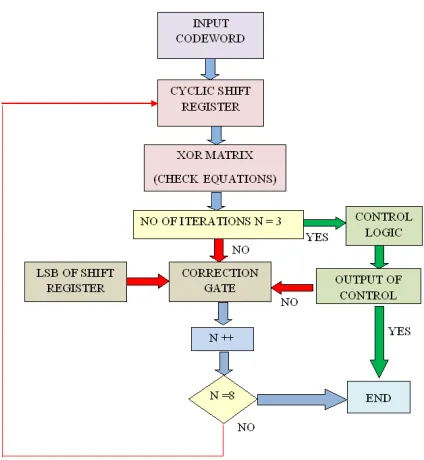
3.1 MMLDC Flow diagram
Fig.3. Flow diagram of MMLDC
In MMLDC, the input codeword is stored in the cyclic shift register. An array of XOR gates computes the value of check equations. Based on the outcome of check equations, control logic detects the presence of error in the codeword. MMLDC takes 3 iterations to detect the error. A counter is used to count the number of iterations. At the end of third iteration, the error correction occurs when one outcome of the majority logic is “1”. The process of error correction is same as that of MMLD.
4. Result discussion
4.1MMLD
After the process of encoding, a codeword is obtained to which a one-bit error or two-bit error is added. Now the erroneous data is passed to MMLD. In the first iteration, the data will be loaded to the cyclic shift register and the parity check equations will be computed.
Fig 4. Simulation result of MMLD of (15, 7) DS-LDPC
If the number of 1’s is greater than the number of 0’s, then there is an error in the codeword. So, the LSB of the codeword is XOR’ed with the output of majority logic block and is shifted. This is a single iteration. In this manner, 7 iterations takes place and the end of 7th iteration, the corrected message bits is obtained. Fig.4 gives the simulation result of MMLD. Here, the one bit and two bit errors in the message are corrected. In Fig.4, the signal “correcteda” is the final output of MMLD. MMLD takes 7 iterations to complete ED & EC.
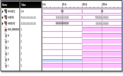
4.2 MMLDC
Fig.5. Simulation result of detection block of MMLDC
Fig.6 gives the simulation result of MMLDC of (15,7)DS-LDPC code. Here “a” is the 7-bit input message to the encoder and “correcteda” is the output of MMLDC. In the encoder, codeword is generated. The codeword gets corrupted which is given by “error_detected_out” in Fig.6. The signal “check” gives the value check equation in the first three iterations. If “error_presence” is “1”, error is present in the message bits so the process of correction is performed. Otherwise the output becomes “0” so there is no error in the message bits. This takes around three iterations for an error-free data.
Fig 6. Simulation result of MMLDC of (15, 7) DS-LDPC
4.3 Comparison of the results
Table.1 shows that the number of iteration is reduced to three in MMLDC which inturn reduces the latency of the LDPC decoder .
Method Number of iterations
MLD 15
MMLD 7
MMLDC 3
5. Conclusion
In this paper, MLD, MMLD and MMLDC are analyzed to correct the error that occurs as a result of MCU. All the methods are simulated using XILINX 14.2 and their results are compared for analysis. The result shows that proposed method (MMLDC) is superior to the existing method (MLD) and MMLD in terms of latency. MMLDC needs 3 iteration for the detection and correction of errors. The latency is thus reduced in MMLDC.
Acknowledgments
Authors would like to thank Mahendra Engineering College, Namakkal and Anna University for their valuable support.
References
[1] R.G.Gallager, “Low-density parity-check codes,” IRE Trans. Inf.Theory, vol. 8, no. 1, pp. 21–28, Jan. 1962
[2] Sarah J. Johnson,” Introducing Low-Density Parity-Check Codes”, School of Electrical Engineering and Computer Science,The University of Newcastle ,Australia.
[3] V. Zyablov and M. Loncar “On the asymptotic performance of low-complexity decoded LDPC codes with constituent hamming codes” IEEE Trans.(VLSI) Sept 2008
[4] W. Liu, J. Rho, and W. Sung, “Low-power high-throughput BCH error correction VLSI design for multi-level cell NAND flash memories,” in Proc. IEEE Workshop Signal Process. Syst. Design Implement.,Oct. 2006, pp. 303–308.
[5] N. Milanidovic and M .P .C. Fossorier,
“Improved bit-flipping decoding of low-density parity-check codes” IEEE Trans.(VLSI) Apr 2009
“Efficient serial message-passingschedules for LDPC decoding,” IEEE Trans. Inf. Theory, vol. 53, no. 11,pp. 4076–4091, Nov. 2007.
[7] J.Cho, J.Kim, and W. Sung, “VLSI implementation of a highthroughput soft-bit-flipping decoder for geometric LDPC codes,” IEEE Trans. Circuits Syst. I, Reg. Papers, vol. 57, no. 5, pp. 1083–1094, May 2010.
[8] Jonghong Kim, Wonyong Sung” Rate-0.9 LDPC Decoding VLSI for Soft-Decision Error Correction of NAND Flash Memory” IEEE Transactions On Very Large Scale Integration (VLSI) Systems, Vol. 22, No. 5, May 2014 [9] Zhengya Zhang,”Design of LDPC Decoders for
Improved Low Error Rate Performance” Electrical Engineering and Computer Science University of California at Berkeley Technical Report No. UCB/EECS-2009-99 July 10, 2009 [10]Pedro Reviriego and Juan A. Maestro “Error