ISSN 2348 – 7968
Micro-mechanical Response of Continuous and Discontinuous Fiber
Composites with Support of Computational Software
Zuzana Murčinková, Michal Halapi
1
Department of Technical Systems Design, Faculty of Manufacturing Technologies with seat in Prešov, Technical University of Košice, Bayerova 1, 080 01 Prešov, Slovak Republic
Abstract
The paper presents basic principles of stress distribution in composite materials reinforced by fibers using the hFEM and pFEM numerical models of squared unit cell (UC). Moreover, paper provides the basic approaches to numerical modeling of composite materials reinforced by short (discontinuous) and continuous fibers and depicts a common and distinctive features of their mechanical behaviour through the analysis of micro-mechanical response.
Keywords: Matrix-Fiber, Micro-mechanics, Stress, Fiber length, Laminate.
1. Introduction
The real material structures consist of different types of in-homogeneities. These in-homogeneities are stress concentrators and cause various local effects. The material micro-structure implies holes, cavities, cracks, inclusions and the material micro-structure can also imply particles and short fibres (straight, curved, waved, continuous fibres). The last mentioned structures are called reinforcing elements as they cause improving the properties. The useful combination of reinforcing elements (shape, size, volume fraction of reinforcing elements, arrangement etc.) and matrix can form the new material – composite material with needful properties.
There are two types of fibre composites: reinforced by continuous (long) and discontinuous (short) fibres. The criteria of classification are different. According to [1] the fiber length of short-fiber composites is significantly smaller compared to the size of the component. The length of continuous (long) fibers is comparable to the size of the component. Another criteria indicator according to literature [2] is aspect ratio, i.e. the ratio of the fiber length L to the diameter D. If aspect ratio L/D is less than 100 (L/D <100) then it is short-fiber composite. If the L/D>100 then the fibers are considered to be long fibers. The long fibers are called also continuous fibers if their length is equal to the size of the component.
The criteria of classification are very coarse and needs to be clarified and completed. In this paper, the short fibers are considered fibers even of L/D > 100 because their dimensions are much smaller than the size of the
component. Such fibers are named relatively short fibers. For example, the diameter of nanotubes can be 4 nm and length even more than 1 mm, i.e. length to diameter ratio L/D is more than 250 000.
The short and relatively short fibres are oriented either randomly or preferably with unidirectional orientation. Such fibres are typical for components made by extrusion, injection moulding or made of non-woven fabrics.
We use computer simulation by commercial computational software to investigate therelations in material structure. P-version and h-version of classical FEM are used in the analyses of microscopic fields. The aim of analyses is micro-mechanical response, especially:
• the distribution of stress,
• the changes due to variable volume fraction of particles and fibers,
• the changes due to other parameters,
• the changes in von Mises Stress and Shear Stress due to size of particles and fibers,
• the comparisons with homogenous material.
2. Micro-mechanical analyses
ISSN 2348 – 7968 Homogenisation is the essential first step towards the
design and analysis of larger scale and loaded structures. Many engineering problems are solved at macroscopic scale with such homogenized properties. However, sometimes such analyses are not accurate enough. There are many homogenisation theories and methods. [3, 4, 5, 6] The concept of representative volume element (RVE) and/or unit cell (UC) is used. The most composite materials exhibit statistical homogeneity. [7] Hill, R. [8] defines a representative volume element (RVE), which is entirely typical of the whole mixture on average and contains a sufficient number of inclusions for the apparent overall properties to be effectively independent of the boundary conditions. RVE as any block of material the analyst wants to use for the micromechanical analysis to find the effective properties and replace it with an equivalent homogeneous material. [9, 10] The term unit cell (UC) is also used extensively in the literature and defined as the building block of the heterogeneous material. We define UC as the smallest RVE. In other words, one RVE could contain several UCs. RVE represents the repetitive unit cell – periodic micro-structure. In case of randomly distributed reinforcing elements of different dimensions and geometry, the concept of statistical representation of representative volume element (RVE) and repeating unit cell (RUC) is used. [3, 11]
2.1 Discontinuous fibers
The short-fiber composite materials are made for example of carbon, ceramic, metal, polymers, glass, etc. with matrixes of polymers, metals and ceramics.
The square pattern is a reason for use of square UCs. As the advantage of UC symmetry of geometry and boundary conditions is used, the eights of models are modelled and computed (Fig. 1, right). The constant displacement in the direction of y-axis equals to 5x10⁻⁵. It is prescribed in the whole upper surface. The dimensionless model is used. The symmetry boundary conditions are defined for the other 5 surfaces. The following assumptions of computing are:
• The fibers are straight, cylindrical. The particles and fibers are regularly distributed without overlapped configuration.
• The ends of each fiber are modelled as half-spheres to avoid singularity.
• The particle (fiber) and matrix create the
continous material without gaps and slip.
• The material of both matrix and particle (fiber) is considered to be isotropic linear elastic.
• Any interface layer is not assumed between fiber and matrix.
• The ideal cohesion between matrix and particle (fiber) is assumed.
The numerical analyses showed that the most stressed locations are the middle part of fiber, interface fiber/matrix, ends of fibers in case of no-overlapping fibers. In case of overlapping fibers the larger stress is also in such parts of fibers that are close to end of neighboring fiber. The stress concentration on the fiber end influencing the stress distribution in the neighboring fiber. The most stressed locations are responsible for de-cohesion and re-cohesion, de-bonding of fibres, fracture of fibre.
The use of composite material does not mean the lower stress in micro-structure, but means much higher modulus of elasticity of structure and carrying capacity. Comparing stress values in matrix and fiber, the larger stress is in fibers. Naturally, the ultimate stress of fiber material is much higher than that of matrix. The fibers are load carrying phase of composite.
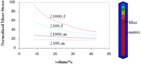
Fig. 1 Normalized von Mises Stress in matrix and fibers R1 (f – fiber, m-matrix), (left),Mises Stress distribution in UC (right).
Fig. 1, left, shows the typical attribute of fiber composites: the lower volume fraction of fiber the larger stress in fiber. Normalized stress means ratio σVM/σ0 where σVM is maximum von Mises stress and σ0 is maximum von Mises stress in material without reinforcing element, i.e. only “pore”. For compared cases in the figure, the von Mises stress is 2.2 – 3.3 times larger in fiber (in dependence on aspect ratio of modulus of elasticity) when volume fraction is the lowest (9 vol%). The stress in the fibre can exceed the largest stresses in the matrix by several orders. Fig. 1, right, provides the stress distribution in UC.
ISSN 2348 – 7968
Fig. 2 Mises Stress of fiber L50/R1 for various Em/Ef (up) and Mises
Stress due to fiber length, Em/Ef : 1/100 (down)
Fig. 2, up, presents the sensitivity of short fiber composite to matrix and fiber material properties, namely Em andEf is Young modulus of matrix and fiber, respectively. Naturally, the larger difference in fiber and matrix material properties, the larger stress in fiber. But if the ratio Em/Ef (compare 1:10 and 1:1000) is larger 100-times, the Mises stress is larger only about 10-times keeping the same dimensions and boundary conditions. The stiffer fiber in matrix is not disadvantage.
Fig. 2, down, shows the relationship between fiber length and Mises Stress. The material properties and boundary condition are the same for each numerical model. The middle part of fibre carries the largest stress. If the fiber length is 8-times larger (compare L25 and L200), the Mises stress is 3-times lower.
Fig. 3 Mises stress in fiber axis due to change of fiber volume fraction
Fig. 3 provides the influence of another parameter, i.e. volume fraction. The more fibers in volume, the lower stress in each fiber. If the volume fraction is 7-times larger, the Misese stress is only 3.75 lower.
Fig. 4 Shear Stress in fiber/matrix interface of fiber of fiber L50/R1 for various Em/Ef (up) and Shear Stress due to fiber length Em/Ef: 1/100
(down)
ISSN 2348 – 7968 areas of beginning of matrix damage. Maximum shear
stress between the fibre and the matrix can result in de-bonding of the fibres or to de-cohesion and re-cohesion at the ends and also in the middle of a fibre close to neighboring fibre. The elasticity and strength limit of composite material depend on the connectivity between fiber and matrix, not only on suitable combination of matrix/fiber materials. However, the aim is not to make the stiff connection at the ends as it would seem as it causes the very high gradients of shear stress at the ends. Nevertheless, the effect of de-cohesion and re-cohesion at the ends of fibers are appropriate regarding material damping.
2.2 Continuous fibers
Laminate composites are well known composite materials applied in the aerospace industry and extend from commercial to military aircraft. According to [12] a lamina or ply is a typical sheet of composite material; a laminate is a collection of laminae (plies) stacked to achieve the desire stiffness and thickness. Moreover, the sequence of various orientations of a fibre-reinforced composite layer in a laminate is termed the lamination scheme (or stacking sequence).
The most of commercial software have involved the modules for numerical simulation of laminates based on plate theory. Classical theory originally developed for thin elastic shells are based on the Love-Kirchhoff assumptions (thin plate theory or Kirchoff’s classical plate theory); more in [13, 14, 15]. This theory neglects the effect of transverse shear deformations. Classical lamina theory is applicable to orthotropic continuous fibre laminated composites only. The Mindlin–Reissner plate theory (thick plate theory) is an extension of Kirchhoff–Love plate theory that takes into account shear deformations through-the-thickness of a plate. [12, 13]
The individual plies suitable for numerical simulations by use of plate theories are unidirectional and bidirectional. The woven and randomly distributed fibres in plies need the different approaches based conception of RVE or UC to estimate the material properties of such ply.
2.2.1 General approach to make the numerical
laminate model
The following approach is general for commercial software. It can be different in details. The used figures are of Abaqus.
1. Modeling the CAD model
The numerical models of laminates are modeled as plates or shells (that have same characteristics as plates, but curvature is an additional one). Shells are sometimes referred to as curved plates
or a plate may be considered as a special limiting case of a shell that has no curvature. The thickness h is much smaller than the typical plate dimension L, h«L. The presented model is defined as 3D shell model meshed by 2D shell elements. 2. Defining material axes regarding the coordinate
system
The laminates are directionally oriented materials. Material axes are denoted 1, 2, 3. Material axis 1 is axis of fiber direction.
3. Defining the ply material properties.
Material constants for presented model are Young modulus (E1, E2) in direction s 1, 2, Poisson's ratio (Nu12) and shear modulus (G12, G13, G23) as shown in Tab. 1. The specific values can be define according to material lists (in presented model) that are estimated experimentally or numerically by concept of RVE or UC or analytically. Tab. 1 provides the material properties of core and glass-epoxy lamina.
Table 1: Material properties of core and lamina
Material Core Lamina
E1 [MPa] 10 35000
E2 [MPa] 10 7500
Nu12 0.3 0.3
G12 [MPa] 1 3600
G13 [MPa] 30 3000
G23 [MPa] 30 3000
4. Defining the laminate
The laminate is characterized by several parameters, as following: number of plies, ply thickness, layup orientation regarding global coordinate system and laminate (layup) sequence. The presented model involves core and symmetry layup where midplane is represented by core that is to receive the added layers.
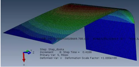
5. Assigning the laminate to model. 6. Computing and interpreting results
Stress distribution in ply 8 is shown in Fig. 5.
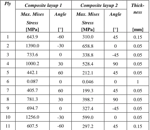
ISSN 2348 – 7968 Table 2: Comparison of two different laminate layup configurations
Ply Composite layup 1 Composite layup 2
Thick-ness
[mm]
Max. Mises
Stress
[MPa]
Angle
[°]
Max. Mises
Stress
[MPa]
Angle
[°]
1 643.9 -60 310.0 45 0.15
2 1390.0 -30 658.8 0 0.05
3 733.6 0 338.8 -45 0.05
4 1000.2 30 528.4 90 0.05
5 442.1 60 212.1 45 0.05
6 0.087 0 0.046 0 1
7 405.7 60 199.3 45 0.05
8 781.3 30 398.7 90 0.05
9 694.7 0 327.4 -45 0.05
10 1256.0 -30 599.0 0 0.05
11 607.5 -60 297.2 45 0.15
3 Conclusion
The paper presents basic principles of stress distribution in composite materials reinforced by fibers using the hFEM and pFEM numerical models of square UC. Moreover, paper the basic approaches to numerical modeling of composite materials reinforced by short (discontinuous) and continuous fibers.
It was confirmed that the final micro-mechanical response of short (discontinuous) and continuous placed in matrix is different; the reinforcing elements are load carrying elements; the connectivity of matrix and reinforcing elements and interface between matrix and reinforcing elements are very important. The composites reinforced by continuous fibers are easier for numerical simulation as the commercial software involve the modules intended for laminates or there are specialized software. In generally, the critical step of numerical simulation is material properties estimation.
The analyses show the fibers are used mainly for improving the composite material strength and the material properties of new (composite) material depend on several parameters (matrix/fiber, Young modulus ratio, fiber length, aspect ratio of fiber, volume fractions etc.) that need to be optimized. Moreover, the distribution of fibers and their interactions influences the macro-mechanical behaviour. It has to be taken into account when designing the composite material.
References
[1] B. Kratochvíl, V. Švorčík, D. Vojtech, Úvod do studia materiálů (Introduction to the study of materials). VŠCHT, Prague, 2005.
[2] J. Jancár: Úvod do materiálového inženýrství polymerních kompozitu (Introduction to Materials Engineering of polymer composites). VUT in Brno, Chemical faculty, Brno, 2003. [3] M.J. Pindera, H. Khatam, A.S. Drago, Y. Bansal:
Micromechanics of spatially uniform heterogeneous media: A critical review and emerging approaches, Composites: Part B Vol. 40, 2009, pp. 349–378.
[4] B. Klusemann, H.J. Böhm, B. Svendsen: Homogenization methods for multi-phase elastic composites with non-elliptical reinforcements: Comparisons and benchmarks, European Journal of Mechanics – A/Solids, 2012, p. 20. [5] P. Kanouté, D.P. Boso, J.L. Chaboche, B.A. Schrefler:
Multiscale Methods for Composites: A Review, Arch Comput. Methods Eng., Vol. 16, 2009, pp. 31–75.
[6] N. Charalambakis: Homogenization Techniques and Micromechanics. A Survey and Perspectives, Applied Mechnics Reviews, Vol. 63, 2010.
[7] Z. Hashin: Analysis of composite materials – a survey, Applied Mechanics Review, Vol. 50, 1983, pp. 481–505. [8] R. Hill, Elastic properties of reinforced solids: some
theoretical principles, Journal of Mechanics and Physics of Solids, Vol. 11, 1963, pp. 357–372.
[9] C.Y. Lee, W. Yu, Homogenization and dimensional reduction of composite plates with in-plane heterogeneity, International Journal of Solids and Structures, Vol. 48, No.10, May 2011, pp. 1474–1484.
[10] W. Yu and T. Tang: Variational Asymptotic Method for Unit Cell Homogenization, Solid Mechanics and its Aplications, 2009, p. 14.
[11] Y. Pan, L. Iorga and A.A. Pelegri, Numerical generation of a random chopped fiber composite RVE and its elastic properties, Composites Science and Technology Vol. 68, 2008, pp. 2792–2798.
[12] J.N. Reddy, Mechanics of Laminated Composite Plates and Shells, Theory and Analysis, 2nd Edition, CRC Press, 2004. [13] E. Ventsel and T. Krauthammer: Thin Plates and Shells,
Theory, Analysis, and Applications, Marcel Dekker, Inc. New York, 2001.
[14] V. Laš, Mechanika kompozitních materiálů (Mechanics of Composite Materials), University of West Bohemia, Pilsen, 2008.
[15] V. Kompiš, Z. Murčinková, P. Droppa, K., Computational simulations of toughening mechanisms for composite materials of short and middle-large-aspect-ratioreinforced composites. In Composite Materials in Theory and Practice K. Frydrýšek ed., pp. 1-21, VŠB – TU Ostrava, 2013.
Zuzana Murčinková, MSc. 1997 (Mechanical Engineering), PhD. 2006
Applied Mechanics), Assoc. prof. 2012 (Production Machine-tools); is employed at Faculty of Manufacturing Technologies, Technical Univesity of Košice. Author has 20 and 10, 54 and 28 Scopus and Web of Science publications and citations, respectively, and others. Author deals with the mechanics of materials and computational mechanics. (author of 1, 2 (except 2.2.1.) and 3 chapters).
Michal Halapi, MSc. 2014 (Computer Aided Manufacturing