Article
1
A dislocation-scale characterization of the evolution
2
of deformation microstructures around
3
nanoindentation imprints in a TiAl alloy
4
Antoine Guitton 1,2,*, Hana Kriaa 1,2, Emmanuel Bouzy 1,2, Julien Guyon 1,2 and Nabila Maloufi 1,2
5
1 Laboratoire d’Étude des Microstructures et de Mécanique des Matériaux (LEM3) – UMR CNRS 7239 –
6
Université de Lorraine, 7 rue Félix Savart, BP 15082, 57073 Metz Cedex 3, France
7
2 Laboratory of Excellence on Design of Alloy Metals for low-mAss Structures (DAMAS) – Université de
8
Lorraine, France
9
* Correspondence: [email protected]; Tel.: +33-372-747-787
10
11
Abstract: In this work, plastic deformation was locally introduced at room temperature by
12
nanoindentation on a γ-TiAl based alloy. Comprehensive analyzes of microstructures were
13
performed before and after deformation. In particular, the Burgers vectors, the line directions and
14
the mechanical twinning systems were studied via accurate electron channeling contrast imaging.
15
Accommodation of the deformation are reported and a scenario is proposed. All features help to
16
explain the poor ductility of the TiAl based alloys at room temperature.
17
Keywords: TiAl alloys, dislocation, twinning, nanoindentation, ECCI
18
19
1. Introduction
20
Titanium aluminide alloys have attracted considerable attention due to their unique
21
combination of properties such as high specific strength and stiffness, good creep properties and
22
resistance against oxidation and corrosion [1] [2], which make them suitable candidate materials for
23
High Temperature (HT) applications [3] [4].
24
One of the main weaknesses of TiAl alloys is that they are brittle at Room Temperature (RT),
25
i.e. below their brittle-to-ductile transition temperature, which lies between 800°C and 1000°C [5].
26
Despite intense research on the HT behavior of TiAl alloys, literature suffers from a lack of
27
understanding on their RT behavior particularly on the elementary deformation mechanisms and the
28
precise role of microstructures [6] [7] [8].
29
Among the several Ti-Al alloy phases, two of them are ordered at RT [4]: γ as the major phase
30
and α2 as a minor phase. The α2 phase is hexagonal (c
a= 0.8) with a DO19 structure while the γ phase
31
is tetragonal with a L10 structure close to cubic (c a=
c
b=1.02). Therefore, six order variants are possible.
32
They can be visualized as generated by a 120° rotation around the 1 1 1 plane normal [9].
33
The microstructures of γ-TiAl alloys are complex. A good compromise for balancing
34
properties between RT plasticity, high strength and good creep resistance at HT can be obtained for
35
the duplex microstructure. It is constituted of a mixture of monolithic γ grains and small lamellar
36
colonies of γ and α2 [10] [11].
37
In dual-phase TiAl alloys, plastic deformation mainly occurs on the 1 1 1 planes of the γ
38
phase by dislocation glide or twinning. It is strongly related to the ordered L10 structure [12]: along
39
the 1 1 0 -directions, there is only one sort of atoms (Ti or Al). In this case, dislocations are called
40
ordinary dislocations, and their Burgers vectors are 1
2 1 1 0 types. Because Ti-atoms and Al-atoms
41
interchange in 0 1 1 -directions, the 1 1 2 and the 1 0 1 dislocations are called
42
superdislocations. These two types of superdislocations can undergo various dissociations into
43
superpartials i.e. partial dislocations with the associated planar faults. In addition, true twinning
44
along 1
6 1 1 2 1 1 1 occurs that does not alter the ordered L10 structure of the γ-TiAl. Because of the
45
specific structure of the γ-TiAl, it is relatively easy to know the direction for either slip of ordinary
46
dislocations or for true twinning when the slip/twin plane is known [12]. Note also that at RT
47
twinning and then glide of ordinary dislocations are the easiest deformation modes [2] [7] [8]. In this
48
manner, Kauffmann et al. suggested that increasing deformation leads to the nucleation of only a few
49
new mechanical twins since the dislocation movement becomes more dominant with increasing
50
strain [8].
51
Although it is accepted that the α2 phase does not contribute to the deformation [6] [12],
52
evidences of prismatic slip 〈1 2 1 0〉 1 0 1 0 , basal slip 〈1 2 1 0〉 0 0 0 1 and pyramidal slip
53
〈1 1 2 6〉 1 2 1 1 were reported [12].
54
Among the difficulties encountered for understanding the mechanical behavior of TiAl based
55
alloys, most of our detailed knowledge on their deformation mechanisms has been deduced from
56
Transmission Electron Microscopy (TEM) observations on an electron transparent lamella [13] [7].
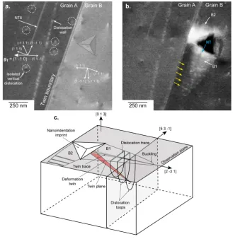
57
The investigation presented in this article focuses on the study of deformation mechanisms at the
58
mesoscopic scale. With an original combination of experiments, we investigate the evolution of
59
deformation microstructures at RT in the γ phase of a dual-phase bulk TiAl alloy. Because of the RT
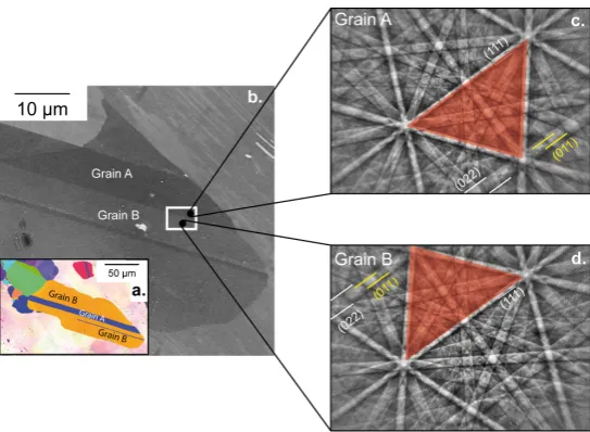
60
brittleness of this material, plastic deformation is induced by nanoindentation. The solid confinement
61
around the indent maintains the integrity of the sample, while applying the load. Note also, that
62
nanoindentation is a surface technique, so that the stress state at the specimen surface is different to
63
that in the volume. The evolution of the microstructures is characterized by accurate Electron
64
Channeling Contrast Imaging (aECCI) before and after deformation.
65
2. Materials and Methods
66
The fully dense Ti–46.8Al–1.7Cr–1.8Nb (at.%) sample was obtained in the form of investment
67
cast-bars (diameter 15 mm, height 230 mm) from Howmet. The as-received bars were hot isostatically
68
pressed at 1250°C and 125 MPa for 4 hours, then subjected to a homogenization treatment in a furnace
69
under vacuum at 1270°C for 24 hours [14]. Then the sample was ground using silicon carbide paper
70
and to avoid any work hardening due to conventional grinding, a chemo-mechanical polishing has
72
been performed using a colloidal silica suspension.
73
Because deformation occurs mainly in the γ-phase [5], plastic deformation was locally
74
introduced on the γ phase by nanoindentation using the Ultra Nanoindentation Tester from Anton
75
Paar (Switzerland), equipped with a Berkovich indenter. The indents were organized in a regular
76
array of 500 µN indents. For easier recognition, it was surrounded by 20 mN indents away at few
77
hundreds of µm.
78
Detailed characterizations of microstructures before and after deformation were performed
79
by aECCI using a Zeiss Auriga Scanning Electron Microscope (SEM) operating at 10 kV. aECCI is a
80
non-destructive method offering the ability to provide, inside a SEM, TEM-like diffraction contrast
81
imaging of sub-surface defects (at a depth of about one hundred of nanometers) on centimetric bulk
82
specimen. Defects, such as dislocations, can be characterized by applying the TEM extinction criteria
83
[15] [16]. Because the yield of BSE depends drastically on the orientation of the crystal relative to the
84
incident electron beam i.e. optic axis of the SEM, obtaining the crystallographic orientation of the
85
grain of interest with an accuracy of 0.1° is a preliminary step to aECCI [16]. The precise orientation
86
of the crystal in the SEM coordinate system is given through Selected Area Channeling Pattern
87
(SACP). To overcome this challenge, rocking the incident electron beam at a pivot point on the surface
88
of a given grain of the sample provides High-Resolution Selected Channeling Patterns (HR-SACP)
89
[17]. HR-SACP cover an angular range of 4.4° and reach an accuracy for the orientation better than
90
0.1° with a spatial resolution less than 500 nm. Because of this small angular range, for getting the
91
orientation of the grain of interest, the HR-SACP is superimposed on an Electron BackScattered
92
Diffraction (EBSD) pattern simulated at 0° using “Esprit DynamicS” software from Bruker. Note that,
93
the reason for using an EBSD pattern (acquired at 70°) simulated at 0° is that the specimen is initially
94
placed at 0° for aECCI.
95
EBSD experiments were carried out on a Zeiss Supra 40 SEM operating at 20 kV. In order to
96
discriminate the different order variants of γ-TiAl, fine EBSD analyses were performed at a step of
97
75 nm with Channel 5 as the indexation software.
98
3. Results
99
3.1. Characterization of the microstructure around the regions of interest
100
Figure 1.(a) and Figure 1.(b) show the microstructure around the Regions of Interest (ROI): ROI1 on
101
grain A away from any interfaces and ROI2 over both grains A and B. ROI1 and ROI2 are presented
102
in Figure 2 and Figure3 respectively. Note that, references [18] and [19] mentioned that interfaces
103
play an important role in TiAl alloys, thus controlling the yield stress.
104
106
Figure 1. (a) EBSD orientation map of the zone of interest. (b) Enhanced BSE image showing the
107
microstructure before deformation. The nanoindentation array is localized in the white rectangle. (c)
108
and (d) EBSD patterns corresponding to grains A and B.
109
110
Figure 2. ROI1 for which the surface is close to 4 5 7 . (a) aECCI obtained with g1= 1 1 0 showing
111
six 1 1 2 1 1 1 Nano-Twins (NT) and the position of the imprint (transparent Berkovich imprint).
112
The white arrows indicate the trace of the 1 1 1 planes. (b) Enhanced BSE image showing the
113
500 µN indent. Two areas (labelled Area 1 and 2) have changed. The NT7 slightly visible in (b) comes
114
116
Figure 3. ROI2, where the surface plane is near 4 5 7 for the twin A (left) and near 0 1 3 for grain
117
B. The TB corresponds to the 1 1 2 1 1 1 system. (a) aECCI obtained with g1= 1 1 0 with the
118
transparency position of the Berkovich imprint. The white arrows indicate the trace of the 1 1 1
119
planes. (b) Enhanced BSE image showing two buckling areas (labelled B1 and B2)clearly visible
120
around the 500 µN indent. The blue arrow points to a NT and the yellow to dislocations. (c) 3D
121
schematic of B1 and B2.
122
Experimentally, the twin nature (true or pseudo twin) is determined using the high-resolution
123
spot mode EBSD. Patterns are collected by manually pointing the electron beam at both sides of the
124
Twin Boundary (TB). The corresponding EBSD patterns (Figure 1.(c) and Figure 1.(d)) clearly indicate
125
that the grains A and B are true twin related: for example, the red triangle formed by the 3 bands
126
depicted in Figure 1.(c).(d) and the 0 1 1 superlattice band are in symmetrical position with respect
127
to the unchanged 1 1 1 band when going from grain A to grain B.
128
The evolution of the ROI1, before and after deformation, is presented on Figure 2.(a) (ECC
129
image) and Figure 2.(b) (BSE micrograph). Due to a rapid contamination of the sample surface under
130
the electron beam, controlling the channeling conditions after deformation with the required
131
accuracy for aECCI was not possible. However, enhanced BSE images were acquired and bring the
132
necessary information for understanding the evolution of the microstructure already fully
133
EBSD gives 42 54 73 ~ 4 5 7 as surface plane so that seven channeling conditions or
135
diffracting vectors g are accessible by tilting and rotating the specimen: g1= 1 1 0 , g2= 1 1 1 ,
136
g3= 3 1 1 , g4= 3 3 1 , g5= 1 3 3 , g6= 1 3 1 , g7= 4 0 2 (note that only the ECC image taken with
137
g1 is shown in Figure 2.(a)). In such conditions, all defects are expected to be in contrast. Neither
138
dislocation nor superdislocation are observed before deformation in Figure 2.(a). Only parallel linear
139
contrasts (labelled NT) are clearly visible. In addition, they are aligned along the ~ 2 3 1 direction.
140
Such BSE contrast is generally attributed to Nano-Twins (NT) and is consistent with 1 1 2 1 1 1
141
as true twin system [20] [21] [22]. After deformation (see Figure 2.(b)), no dislocation is visible, but
142
changes clearly identifiable are localized in the vicinity of the indent (Area 1 and Area 2 in Figure
143
2.(b)). In Area 1, near the imprint, a 1 1 2 1 1 1 deformation NT was created. At the other side of
144
the imprint (Area 2) the NT5 extends along the ~ 2 3 1 . Note that the NT7 visible in Figure 2.(b)
145
comes from a neighbor imprint.
146
3.3 Microstructure evolution of the ROI2
147
ROI2 is composed by two twinned grains A (left) and B (right) with their surface plane as
148
42 54 73 ~ 4 5 7 and 16 325 946 ~ 0 1 3 respectively (see Figure 3.(a)). The common direction
149
on the sample surface for both grains A and B is 2 3 1 . The 1 1 1 -plane, which intercepts both the
150
4 5 7 plane and the 0 1 3 plane along 2 3 1 is the 1 1 1 . Note also that a NT aligned along
151
~ 2 3 1 is visible (labelled NT8 in Figure 3) and consistent with 1 1 2 1 1 1 . The vertical
152
dislocations (i.e. almost perpendicular to the sample surface) either isolated or stacked into a wall in
153
grain A (Figure 3.(a)) are analyzed by aECCI in order to determine their Burgers vectors. Using the
154
diffracting conditions g1 to g7 previously mentioned with invisibility criteria leads to ±12 1 1 0 as
155
the Burgers vector.
156
Unfortunately good channeling conditions are not reachable in the right 0 1 3 grain, resulting
157
in the non-characterization of the isolated vertical dislocations.
158
Figure 3.(b) and its schematic show the ROI2 after deformation. The 500 µN indent was made in the
159
0 1 3 grain near the TB. Around this indent, two similar features (labelled B1 and B2 in Figure 3.(b))
160
are observed. Parallel to the TB i.e. in B1, a set of parallel dislocation traces is visible (yellow arrows
161
from the imprint in the 2 3 1 direction. Such buckling areas were already reported but not
163
explained for TiAl alloys [18] [23].
164
In addition, a NT contrast (blue arrow in Figure 3.(b)) is observed inside B1, and it is parallel to
165
2 3 1 consistent with the 1 1 2 1 1 1 true twinning system.
166
Perpendicular to the TB i.e. along 5 3 1 , another buckling area B2 is observed, and it cannot extend
167
because it is blocked by the TB. In the neighbor 4 5 7 grain, no change is observed compared to the
168
initial state, even if the TB is distorted locally where B2 is in contact. Outside both buckling areas, no
169
other defect is observed.
170
4. Discussion
171
From observations of the evolution of microstructures of ROI1, two assessments can be made:
172
1. at RT, twinning is observed to be the main deformation mechanism, in agreement with literature
173
[2] [7] [8]. But contrary to Zambaldi et al., who prefer to suggest that ordinary dislocation glide
174
is the main deformation mechanism at RT (without totally excluding twinning) from
175
observations by atomic force microscopy around high load (3000 µN) imprints [18].
176
2. deformation is observed to be localized near the indent.
177
In many materials, buckling areas such as those characterized in ROI2 are associated with a
178
canalization of the deformation, generally taking its origin from the accommodation of twins [24].
179
Although the accommodation of 1
6 1 1 2 1 1 1 twin by 1
2 1 1 0 1 1 1 ordinary dislocations was
180
already reported by TEM experiments in TiAl alloys [25] [26], no mechanism was proposed.
181
From this knowledge, and taking into account our results, we propose the following scenario (see
182
Figure 3.(c)):
183
• Under the indent, the 1 1 2 1 1 1 NT is formed.
184
• The stress concentration at the tip of the 1 1 2 1 1 1 NT nucleates ordinary ±1
2 1 1 0
185
dislocation loops gliding in the 1 1 1 planes. The dislocation loops will form an ellipsoid
186
surrounding the NT thus producing lines after projection on the observation plane.
187
• The elliptical area or B1 will grow by adding successive dislocation loops at its extremity.
188
• B1 will extend until it will meet an obstacle such as the TB (for B2 for example).
189
• At the location where B2 intercepts the TB, a stress concentration appears. It results in a local
190
distortion of the boundary. Therefore the TB seems to be a strong obstacle to the propagation of
191
the deformation and at higher load it may cause microcracking at its vicinity as observed in
192
references [18] [26] [27].
193
Furthermore, we can suggest that the low load used (500 µN) is just high enough for generating a
194
complex and non-uniaxial stress field at the tip of the indent. This leads to the activation of the main
195
deformation mechanism i.e. twinning, but it is too low for dislocation glide. For higher loads, both
196
mechanisms are activated subsequently, and lead to the formation of a buckling area, according to
197
5. Conclusions
199
In summary, RT nanoindentation tests combine with aECCI observations before and after
200
deformation bring novel insights into the γ-TiAl deformation mechanisms:
201
1. At RT, twinning is observed to be the main deformation mechanism.
202
2. Twinning is accommodated by ordinary dislocation mechanism leading to the canalization of
203
the deformation.
204
3. TB can play the role of obstacle to the propagation of deformation to neighbor grains leading to
205
a stress concentration at the vicinity of the boundary. Therefore, the true twin seems to be one of the
206
weak links explaining the poor ductility of γ-TiAl at RT.
207
208
209
Acknowledgments: The author thank Dr. N. Gey from the LEM3 for discussions.
210
Author Contributions: All experimental observations were performed by HK and AG. AG and HK performed
211
the dislocation analyses. AG wrote the main manuscript. All the authors participate in the discussion and they
212
reviewed the manuscript.
213
Conflicts of Interest: The authors declare no conflict of interest.
214
References
216
[1] Kim, Y.; Dimiduk, D. Progress in the understanding of gamma titanium aluminides, JOM 1991,
217
43, pp. 40-47, doi: 10.1007/BF03221103.
218
[2] Appel, F.; Wagner, R. Microstructure and deformation of two-phase gamma-titanium aluminides.
219
Mater. Sc. Eng. R 1998, 22, pp. 187-268, doi:10.1016/S0927-796X(97)00018-1
220
[3] Loria, E. Quo vadis gamma titanium aluminide. Intermetallics 2001, 9, pp. 997-1001, doi:
221
10.1016/S0966-9795(01)00064-4.
222
[4] Schuster, J.; Palm, M. Reassessment of the binary aluminum-titanium phase diagram. J. Phase
223
Equilib. Diff 2006, 27, pp. 255-277, doi: 10.1361/154770306X109809.
224
[5] Zambaldi, C. Micromechanical modeling gamma-TiAl based alloys. RWTH Aachen University,
225
Aachen, 2010; 978-3-8322-9717-6.
226
[6] Appel, F.; Paul, D.; Oehring, M. Gamma titanium aluminide alloys: science and technology,
Wiley-227
VCH Verlaf GmbJ, 2011; 9783527315253.
228
[7] Beran, P.; Heczko, M.; Kruml, T.; Panzner, T.; Van Petegem, S. Complex investigation of
229
deformation twinning in γ-TiAl by TEM and neutron diffraction. J. Mech. Phys. Sol 2016, 95, pp.
230
647-662, doi: 10.1016/j.jmps.2016.05.004.
231
[8] Kauffmann, F.; Bidlingmaier, T.; Dehm, G.; Wanner, A.; Clemens, H. On the origin of acoustic
232
emission during room temperature compressive deformation of a gamma-TiAl based alloy.
233
Intermetallics 2000, 8, pp. 823-830, doi: 10.1016/S0966-9795(00)00025-X
234
[9] Zambaldi, C.; Zaefferer, C.; Wright, S. Characterization of order domains in γ-TiAl by orientation
235
microscopy based on electron backscatter diffraction. App. Crystal 2009, 42, pp. 1092-1101, doi:
236
10.1107/S0021889809036498.
237
[10] Dey, S.; Hazotte, A.; Bouzy, E. Multiscale gamma variant selection in a quaternary near-gamma
238
Ti-Al alloy. Philos. Mag 2006, 2006, no. 86, pp. 3089-3112, doi: 10.1080/14786430600669832.
239
[11] Dey, S.; Morawiec, A.; Bouzy, E.; Hazotte, A.; Fundenberger, J.-J. Determination of
240
gamma/gamma interface relationships in a (alpha2 + gamma) TiAl base alloy using TEM Kikuchi
241
patterns obtained by nanoprobe scanning. Mater. Lett 2003, 60, pp. 646-650, doi:
242
10.1016/j.matlet.2005.09.052.
243
[12] Marketz, M.; Fischer, F.; Clemens, H. Deformation mechanisms in TiAl intermetallics -
244
experiments and modeling. Int. J. Plasticity 2003, 19, pp. 281-321, doi: 10.1016/S0749-6419(01)00036-5.
245
[13]Zghal, S.; Coujou, A.; Couret, A. Transmission of the deformation through γ-γ interfaces in a
246
polysynthetically twinned TiAl alloy. Philos. Mag 2001, 81, pp. 345-382, doi:
247
10.1080/01418610108214308.
248
[14] Dey, S.; Hazotte, A.; Bouzy, E.; Naka, S.Development of Widmanstätten laths in a near-gamma
249
TiAl alloy. Acta Mater 2005, 53, pp. 3783-3794, doi: 10.1016/j.actamat.2005.04.007
250
[15] Mansour, H.; Guyon, J.; Crimp, M.; Gey, N.; Beausir, B.; Maloufi, N. Accurate electron channeling
251
contrast analysis of dislocations in fine grained bulk materials. Scr. Mater 2014, 84-85, pp. 11-14, doi:
252
10.1016/j.scriptamat.2014.03.001.
253
[16] Kriaa, H.; Guitton, A.; Maloufi, N. Fundamental and experimental aspects of diffraction for
254
characterizing dislocations by electron channeling contrast imaging in scanning electron microscope.
255
[17] Guyon, J.; Mansour, H.; Gey, N.; Crimp, M.; Chalal, S.; Maloufi, N. Sub-micron resolution selected
257
area electron channeling patterns. Ultromicro 2015, 149, pp. 34-44, doi: 10.1016/j.ultramic.2014.11.004
258
[18] Zambaldi, C.; Raabe, D. Plastic anisotropy of gamma-TiAl revealed by axisymmetric indentation.
259
Acta Materialia 2010, 58, pp. 3516-3530, doi: 10.1016/j.actamat.2010.02.025
260
[19] Kad, B.; Asaro, R.J. Apparent Hall-Petch effects in polycrystalline lamellar TiAl. Philos. Mag. A
261
2006, 75, no. 1, pp. 87-104, doi: 10.1080/01418619708210284
262
[20] Simki, B.; Ng, B.; Crimp, M.; Bieler, T. Crack opening due to deformation twin shear at grain
263
boundaries in near-γ TiAl. Intermetallics 2007, 15, pp. 55-60, doi: 10.1016/j.intermet.2006.03.005
264
[21] Simki, B.; Crimp, M.; Bieler, T. A factor to predict microcrack nucleation at γ–γ grain boundaries
265
in TiAl. Scripta Mat 2003, 49, pp. 149-154, doi: 10.1016/j.intermet.2006.03.005
266
[22] Ng, B.; Simki, B.; M. Crimp, M.; Bieler, T. The role of mechanical twinning on microcrack
267
nucleation and crack propagation in a near-γ TiAl alloy. Intermetallics 2004, 12, pp. 1317-1323, doi:
268
10.1016/j.intermet.2004.03.015.
269
[23] Gehard, S.; Pyczak, F.; Göken, M. Microstructural and micromechanical characterisation of TiAl
270
alloys using atomic force microscopy and nanoindentation. Materials Science and Engineering A
271
2009, 523, pp. 235-241, doi: 10.1016/j.msea.2009.05.068.
272
[24] Hirth, J. P.; Lothe, J. Theory of dislocations, 2nd ed.; Krieger Publishing Company, 1982, pp 756;
273
0521864364.
274
[25] Gibson, M.; Forwood, C. Slip transfer of deformation twins in duplex γ-based Ti-Al alloys: Part
275
III. Transfer across general large-angle γ-γ grain boundaries. Philos. Mag. A 2002, 82, no. 7, pp.
1381-276
1404, doi: 10.1080/01418610208235678
277
[26] Simki, B.; Crimp, M.; Bieler, T. A factor to predict microcrack nucleation at gamma-gamma grain
278
boundary in TiAl. Scr. Mater 2003, 49, pp. 149-154, doi : 10.1016/S1359-6462(03)00216-1
279
[27]Bieler, T.; Fallahi, A.; Ng, B.; Kumar, D. Crimp, M.; Simki, B.; Zamiri, A.; Pourboghrat, F.; Mason,
280
D. Fracture initiation/propagation parameters for duplex TiAl grain boundaries based on twinning,
281
slip, crystal orientation and boundary misorientation. Intermetallics 2005, 13, pp. 979-984, doi: