ISSN (Print) : 2320 – 3765 ISSN (Online): 2278 – 8875
I
nternational
J
ournal of
A
dvanced
R
esearch in
E
lectrical,
E
lectronics and
I
nstrumentation
E
ngineering
(An ISO 3297: 2007 Certified Organization)
Vol. 5, Issue 5, May 2016
Automatic Braking System for Automobiles
Using IR Sensor
Hemalatha B K1, P Pooja2 , Chaithra M3 ,Megha S4,Rakshitha R T5
Assistant Professor, Department of Electrical and Electronics Engineering, SJB Institute of Technology, Bangalore,
Karnataka, India 1
UG Students, Department of Electrical and Electronics Engineering, SJB Institute of Technology, Bangalore,
Karnataka, India 2345
ABSTRACT: Automotive vehicles are increasingly being equipped with collision avoidance and warning systems for predicting the potential collision with an external object, such as another vehicle or a pedestrian. Upon detecting a potential collision, such systems typically initiate an action to avoid the collision and/or provide a warning to the vehicle operator. The aim is to design and develop a control system based on an automatic, intelligent and electronically controlled automotive braking system for automobiles is called as “INTELLIGET BRAKING SYSTEM”. This Braking system consists of IR transmitter and receiver circuit and the vehicle. The IR sensor is used to detect the obstacle. There is any obstacle in the path, the IR sensor senses the obstacle and giving the control signal to the microcontroller, which in turn sends a signal to the motor to stop and also to the solenoid so as to stop the vehicle as programmed. This project facilitates electromagnetic braking system using solenoid. Here in fabrication module include a circular disc associated with a dc motor and a solenoid. Embedded system module includes micro controller with a solenoid and sensor
KEYWORDS: Peripheral Interface Controller (PIC) Microcontroller, Infrared (IR) sensor, Solenoid, Permanent Magnet Direct current (PMDC) motor.
ISSN (Print) : 2320 – 3765 ISSN (Online): 2278 – 8875
I
nternational
J
ournal of
A
dvanced
R
esearch in
E
lectrical,
E
lectronics and
I
nstrumentation
E
ngineering
(An ISO 3297: 2007 Certified Organization)
Vol. 5, Issue 5, May 2016
Braking is basically a mechanical action applied for slowing down of vehicles or even making the vehicle coming to halt depending upon the circumstances.
A.NEED FOR BRAKING SYSTEM
When a safety factor of a vehicle is considered a primary factor that flashes in mind is its brakes or braking system.So a braking system is such a vital component that is necessarily required when a vehicle is considered. It reduces the kinetic energy of the vehicle in conditions when a vehicle has to slow down or also it has to be stopped. Thus making sure the vehicle and the passengers inside it are safe. Thus a braking system is always needed to ensure the safety of the drivers and passengers uncountable valued lives.
B.PROBLEM STATEMENT
The conventional friction brake system is composed of the following basic components: the “master cylinder” which is located under the hood is directly connected to the brake pedal, and converts the drivers’ foot pressure into hydraulic pressure. Steel “brake hoses” connect the master cylinder to the “slave cylinders” located at each wheel. Brake fluid, specially designed to work in extreme temperature conditions, fills the system. “Shoes” or “pads” are pushed by the slave cylinders to contact the “drums” or “rotors,” thus causing drag, which slows the car. Two major kinds of friction brakes are disc brakes and drum brakes.
Disc brakes use a clamping action to produce friction between the “rotor” and the “pads” mounted in the “caliper” attached to the suspension members. Disc brakes work using the same basic principle as the brakes on a bicycle: as the caliper pinches the wheel with pads on both sides, it slows the vehicle (Limpert 1992).
Drum brakes consist of a heavy flat-topped cylinder, which is sandwiched between the wheel rim and the wheel hub. The inside surface of the drum is acted upon by the linings of the brake shoes. When the brakes are applied, the brake shoes are forced into contact with the inside surface of the brake drum to slow the rotation of the wheels (Limpert1992).
Air brakes use standard hydraulic brake system components such as braking lines, wheel cylinders and a slave cylinder similar to a master cylinder to transmit the air-pressure-produced braking energy to the wheel brakes. Air brakes are used frequently when greater braking capacity is required.
All the above mentioned convectional brakes have two chief problems one is the wear and tear and other is unnecessary excessive temperature in the service is attained.
Excessive heating of brakes can result in fade .it causes temporary changes in the friction as they get hotter. Normally efficiency is regained when they cool again Brake pads and linings also wear away faster at higher temperatures.
C.APPROACH TO THE SOLUTION
As seen in the above-mentioned problem with the convectional brakes the problem is arises due to the friction between two or more rubbing parts.
Hence electromagnetic brakes can be used as a replacement which is totally frictionless. And due to which there is no question of wear and tear of parts and unnecessary temperature issues as there is no friction in this braking system.
This results in stable efficiency of the braking system for a longer service span. In addition, it results in longer life span of the braking system without any wear and tear. This also gives the answer for the replacement of cooling system.
ISSN (Print) : 2320 – 3765 ISSN (Online): 2278 – 8875
I
nternational
J
ournal of
A
dvanced
R
esearch in
E
lectrical,
E
lectronics and
I
nstrumentation
E
ngineering
(An ISO 3297: 2007 Certified Organization)
Vol. 5, Issue 5, May 2016
II. HARDWARE COMPONENTS
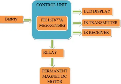
Figure 2 : Internal Circuit Diagram
The fabrication module includes a circular disc associated with dc motor and a solenoid.
The transducer senses the approaching vehicle, represented by field lines and generates a detection signal that is transferred to the controller.
The controller determines whether the detection signal is greater than the pre-determined magnitude, constituting that the approaching vehicle is within a pre-determined distance and/or is accelerating toward or approaching the target vehicle.
After receiving the error signal, the controller warns the operator of approaching vehicle by a warning signal and the brake is applied automatically by stopping the motors, which is running in normal conditions.
In addition, the microcontroller sends the signal to the solenoid, which gets activated to generate magnetic field in the disc provided. This magnetic field generated will oppose the moment of the disc, which is mounted on the wheel of the vehicle thus making the vehicle come to halt.
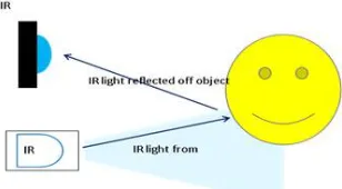
III. IR SENSOR
ISSN (Print) : 2320 – 3765 ISSN (Online): 2278 – 8875
I
nternational
J
ournal of
A
dvanced
R
esearch in
E
lectrical,
E
lectronics and
I
nstrumentation
E
ngineering
(An ISO 3297: 2007 Certified Organization)
Vol. 5, Issue 5, May 2016
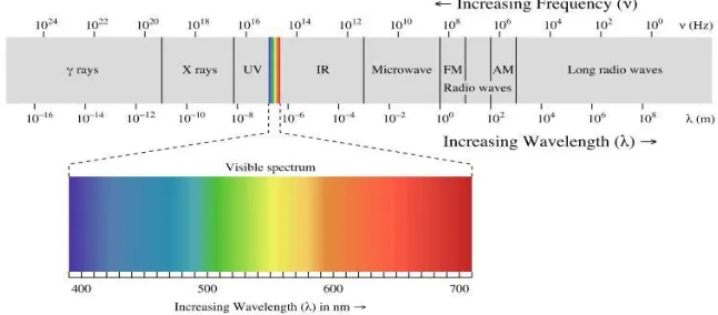
Figure 4: Sensitivity Spectrum
V. MICROCONTROLLER - PIC 16F877A
Figure 5: PIC microcontroller
The microcontroller is a set of digital logic circuits integrated on a single silicon “chip” whose connections and behavior can be specified and later alter when required, by the program in its memory. The great advantage of this is that in order to change the circuit’s structure and operation, all that is needed is a change in the program very little, if any, circuit hardware modifications are necessary. The microcontroller unit used here is a PIC16f877A .The core controller is a mid-range family having a built-in SPI master. 16F877A have enough I/O lines for current need. It is capable of initiating all intersystem communications. The master controller controls each functions of the system with a supporting device. Also responsible for reception of commands from the host and taking necessary actions. PIC16F877A is an 8-bit, fully static, EPROM/EPROM/ROM-based CMOS microcontroller. It employs RISC architecture with only 35 word/single cycle instructions. All these instructions are single cycle (1ms) expect for program branches which takes two cycles. The PIC16f877A products are supported by a full featured macro assembler,
a software simulator, „C‟ compiler etc.
A. SPECIAL MICROCONTROLLER FEATURES
•100,000 erase/write cycle Enhanced Flash program memory typical •1,000,000 erase/write cycle Data EEPROM memory typical •Data EEPROM Retention > 40 years
•Single-supply 5V In-Circuit Serial Programming
•Watchdog Timer (WDT) with its own on-chip RC oscillator for reliable operation •Programmable code protection •Power saving Sleep mode
ISSN (Print) : 2320 – 3765 ISSN (Online): 2278 – 8875
I
nternational
J
ournal of
A
dvanced
R
esearch in
E
lectrical,
E
lectronics and
I
nstrumentation
E
ngineering
(An ISO 3297: 2007 Certified Organization)
Vol. 5, Issue 5, May 2016
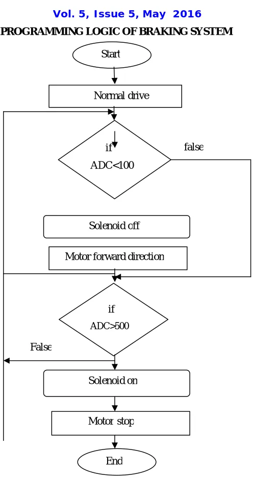
VI.PROGRAMMING LOGIC OF BRAKING SYSTEM
Figure 6: Programming Logic of braking system
VII. APPLICATIONS
Some of the applications of our project are: Used in high speed trains.
Used in military application such as spy robot.
Start
Solenoid off if
ADC<100
Motor forward direction Normal drive
if
ADC>500
Solenoid on
Motor stop
End
false
ISSN (Print) : 2320 – 3765 ISSN (Online): 2278 – 8875
I
nternational
J
ournal of
A
dvanced
R
esearch in
E
lectrical,
E
lectronics and
I
nstrumentation
E
ngineering
(An ISO 3297: 2007 Certified Organization)
Vol. 5, Issue 5, May 2016
Table 1: Condition for Braking operation
Signal strength (db V/m) RESULT
<100 No Braking Operation
>500 Braking Takes Place
This proposed system can be easily implemented near different populated areas. The power of the proposed system lies in its flexibility and capability of development with little hardware changes such as changing the speed limits and speed control methods using the software of the base station in negligible amount of time.
The proposed system is based on microcontroller technology for collecting data related to speed and transmitting it through a transceiver to a base station that analyzes the transmitted data and takes appropriate decisions related to speed limit and control requirements. This experience has encouraged us to learn more about upcoming trends and technologies and thereby adding our bumble knowledge and experience about the vast ocean of electronics.
A revolutionary invention is made in the field of brakes. The Electromagnetic brakes are excellent replacement for conventional automobile brakes. The use of Electromagnetic brakes can be done for lighter vehicles also. With some modification, a regenerative braking system can be equipped with the Electromagnetic brakes. The Electromagnetic brakes are the future of automobile brakes.
The intelligent braking system provides a total safety in the negligence of the driver in the emergency situation thus saving reduction in loss of precious human lives and properties. Thus there is no doubt that this system becomes the future braking system for the automobiles.
In addition to the braking system, an additional module is developed for controlling the direction of the vehicle. The remote controller is developed using RF transmitter and receiver which is interfaced with microcontroller.
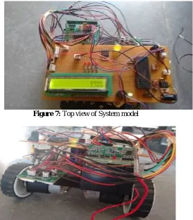
Figure 7: Top view of System model
ISSN (Print) : 2320 – 3765 ISSN (Online): 2278 – 8875
I
nternational
J
ournal of
A
dvanced
R
esearch in
E
lectrical,
E
lectronics and
I
nstrumentation
E
ngineering
(An ISO 3297: 2007 Certified Organization)
Vol. 5, Issue 5, May 2016
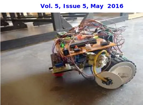
Figure 9: Side view of System model
REFERENCES
1. Fleming, Frank; Shapiro, Jessica “BASIC OF ELECTROMAGNETIC BRAKES”. 2. Zalud Todd, Automatic Braking System using sensorics-“brake selection” .
3. E. Coelingh, H. Lind, W. Birk and D. Wetterberg, Collision Warning with Auto Brake, FISITA World Congress, F2006V130, Yokohama Japan, 2006Collision warning with full brake and pedestrian detection.