A Novel Fuzzy Based Modular Seven Level
Cascaded Inverter Using P and O MPPT for the
Application in Single Or Three Phase Grid
Connected Systems
Meripo Sudheer Teja
1& A.S.S. Veerendra Babu
2PG Scholor1 Assistant Professor2 , Adithya College Of Engineering, JNTU Kakinada
Abstract:
This project illustrates that a novel Fuzzy based modular Seven Level converter applied for grid connected systems used to rectify the distorted current waveforms in a single phase or a three-phase systems by P and O based
technique. The Perturb and Observe MPPT
(maximum power point tracking) is a technique used in solid state converters to extract maximum energy from the photovoltaic (PV) systems. Also increases the system efficiency and flexibility of PV systems which realizes the utilization of maximum solar energy and has a independent control of each bridge and each DC-link. The major advantage of this type is to reduce the distorted current waves a fuzzy based modulation
is presented for a 185W solar system. Some
results such as current, voltage and output power for each various combination have been recorded. The simulation has been accomplished in software of MATLAB Math works.
I. INTRODUCTION
DUE to the shortage of fossil fuels and environmental problems caused by conventional power generation, renewable energy, particularly solar energy, has become very popular. Solar-electric-energy demand has grown consistently by 20%–25% per annum over the past 20 years [1], and the growth is mostly in grid-connected applications. With the extraordinary market growth in grid-connected photovoltaic (PV) systems, there are increasing interests in grid-
This cascaded inverter would maintain the benefits of ―one converter per panel,‖ such as better utilization per PV module, capability of mixing different sources, and redundancy of the system. In addition, this dc/ac cascaded inverter removes the need for the per-string dc bus and the central dc/ac inverter, which further improves the overall efficiency. The modular cascaded H-bridge multilevel inverter, which requires an isolated dc source for each H-bridge, is one dc/ac cascaded inverter topology. The separate dc links in the multilevel inverter make independent voltage control possible. As a result, individual MPPT control in each PV module can be achieved, and the energy harvested from PV panels can be maximized. Meanwhile, the modularity and low cost of
Fig. 1. Configurations of PV systems. (a) Central inverter. (b) String inverter.(c) Multi string inverter. (d) AC-module inverter. (e) Cascaded dc/dc converter. (f) Cascaded dc/ac inverter.
Multi level converters would position them as a prime candidate for the next generation of efficient, robust, and reliable grid connected solar power electronics. A modular cascaded H-bridge multilevel inverter topology for single- or three-phase grid-connected PV systems is presented in this paper. The panel mismatch issues are addressed to show the necessity of individual MPPT control, and a control scheme with distributed MPPT control is then proposed. The distributed MPPT control scheme can be applied to both single and three-phase systems. In addition, for the presented three-phase grid-connected PV system, if each PV module is operated at its own MPP, PV mismatches may introduce unbalanced power supplied to the three-phase multilevel inverter, leading to unbalanced injected grid current. To balance the three-phase grid current, modulation compensation is also added to the control system. A three-phase modular cascaded multilevel inverter prototype has been built. Each H-bridge is connected to a 185-W solar panel. The modular design will increase the flexibility of the system and reduce the cost as well. Simulation and experimental results are provided to demonstrate the developed control scheme.
II. S YSTEM DESCRIPTION
Modular cascaded H-bridge multilevel inverters for single and three-phase grid-connected PV systems are shown in Fig. 2. Each phase consists of n H-bridge converters connected in series, and the dc link of each H-bridge can be fed by a PV panel or a short string of PV panels. The cascaded multilevel inverter is connected to the grid
through L filters, which are
used to reduce the switching harmonics in the current. By different combinations of the four switches in each H-bridge module, three output voltage levels can be generated: −vdc, 0, or +vdc. A cascaded multilevel inverter with n input sources will provide 2n + 1 levels to synthesize the ac output waveform. This (2n + 1)-level
reduction of harmonics in the synthesized current, reducing the size of the needed output filters. Multilevel inverters also have other advantages
such as reduced voltage stresses on
the semiconductor switches and having higher efficiency when compared to other converter topologies [17].
III. PANEL MISMATCHES
PV mismatch is an important issue in the PV system. Due to the unequal received irradiance, different temperatures, and aging of the PV panels, the MPP of each PV module may be different. If each PV module is not controlled independently, the efficiency of the overall PV system will be decreased. To show the necessity of individual MPPT control, a five-level two-H-bridge single-phase inverter is simulated in MATLAB/SIMULINK. Each H-bridge has its own 185-W PV panel connected as an isolated dc source. The PV panel is modeled according to the specification of the commercial PV panel from A strong energy CHSM-5612M. Consider an operating condition that each panel has a different irradiation from the sun; panel 1 has irradiance S
=1000 W/m2, and panel 2 has S = 600 W/m2. If only panel 1 is tracked and its MPPT controller determines the average voltage of the two panels, the power extracted from panel 1 would be 133 W, and the power from panel 2 would be 70 W,
as can
be seen in Fig. 3. Without individual MPPT control, the total power harvested from the PV system is 203 W. However, Fig. 4 shows the MPPs of the PV panels under the different irradiance. The maximum output power values will be 185 and 108.5 W when the S values are 1000 and 600 W/m2, respectively, which means
that the total power harvested from
the PV system would be 293.5 W if individual MPPT can be achieved. This higher value is about 1.45 times of the one before. Thus, individual MPPT control in each PV module is required to increase the efficiency of the PV system. In a three-phase grid-connected PV
system, a PV mismatch may cause more problems. Aside from decreasing the overall efficiency, this could even introduce unbalanced power supplied to the three-phase grid-connected system. If there are PV mismatches between phases, the input power of each phase would be different. Since the grid voltage is balanced, this difference in input power will cause unbalanced current to the grid, which is not allowed by grid standards. For example, to unbalance the current per phase more than 10% is not allowed for some utilities, where the percentage imbalance is calculated by taking the maximum deviation from the average current and dividing it by the average current [18]
Fig. 2. Topology of the modular cascaded H-bridge multilevel inverter for grid-connected PV
systems.
Fig. 4. P–V characteristic under the different irradiance
To solve the PV mismatch issue, a control scheme with individual MPPT control and modulation compensation is proposed. The details of the control scheme will be discussed in the next section.
IV. CONTROL SCHEME
A. Distributed MPPT Control
In order to eliminate the adverse effect of the mismatches and increase the efficiency of the PV system, the PV modules need to operate at different voltages to improve the utilization per PV module. The separate dc links in the cascaded H-bridge multilevel inverter make independent voltage control possible. To realize individual MPPT control in each PV module, the control scheme proposed in [19] is updated for this application. The distributed MPPT control of the three-phase cascaded H-bridge inverter is shown in Fig. 5. In each H-bridge module, an MPPT controller is added to generate the dc-link voltage reference. Each dc-link voltage is compared to the corresponding voltage reference, and the sum of all errors is controlled through a total voltage controller that determines the current reference Idref. The reactive current reference Iqref can be set to zero, or if reactive power compensation is required, Iqref can also be given by a reactive current calculator [20], [21]. The synchronous reference frame phase-locked loop (PLL) has been used to find the phase angle of the grid
voltage [22]. As the classic control scheme in
three-phase systems, the grid currents
in abc coordinates are converted to dq coordinates and regulated through proportional–integral (PI) controllers to generate the modulation index in the dq coordinates, which is then converted back to three phases. The distributed MPPT control
scheme for the single-phase
system is nearly the same. The total voltage controller gives the magnitude of the active current reference, and a PLL provides the frequency and phase angle of the active current reference. The current loop then gives the modulation index. To make each PV module operate at its own MPP, take phase a as an example; the voltages v d c a2 to v d c a n are controlled individually through n − 1 loops. Each voltage controller gives the modulation index proportion of one H-bridge module in phase a. After multiplied by the modulation index of phase a, n − 1 modulation indices can be obtained. Also, the modulation index for the first H-bridge can be obtained by subtraction. The control schemes in phases b and c are almost the same. The only difference is that all dc-link voltages are regulated through PI controllers, and n modulation index proportions are obtained for each phase
Fig. 5. Control scheme for three-phase modular cascaded H-bridge multilevel PV inverter.
A phase-shifted sinusoidal pulse width
can be seen that there is one H-bridge module out of N modules whose modulation index is obtained by subtraction. For single-phase systems, N = n, and for three-phase systems, N = 3n, where n is the number of H-bridge modules per phase. The reason is that N voltage loops are necessary to manage different voltage levels on N H-bridges, and one is the total voltage loop, which gives the current reference. So, only N − 1 modulation indices can be determined by the last N − 1 voltage loops, and one modulation index has to be obtained by subtraction. Many MPPT methods have been developed and implemented [23], [24]. The incremental conductance method has been used in this paper. It lends itself well to digital
control, which can
easily keep track of previous values of voltage and current and make all decisions.
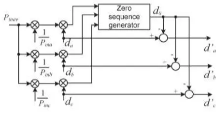
B. Modulation Compensation
As mentioned earlier, a PV mismatch may cause more problems to a three-phase modular cascaded H-bridge multilevel PV inverter. With the individual MPPT control in each H-bridge module, the input solar power of each phase would be different, which introduces unbalanced current to the grid. To solve the issue, a zero sequence voltage can be imposed upon the phase legs in order to affect the current flowing into each phase [25], [26]. If the updated inverter output phase voltage is proportional to the unbalanced power, the current will be balanced. Thus, the modulation compensation block, as shown in Fig. 6, is added to the control system of three-phase modular cascaded multilevel PV inverters. The key is how to update the modulation index of each phase without increasing the
Fig. 6. Modulation compensation scheme.
complexity of the control system. First, the unbalanced power is weighted by ratio r j, which is calculated as
r
j=
PinavPinj
(1)
where Pinj is the input power of phase j (j = a, b, c), and Pinav is the average input power. Then, the injected zero sequence modulation index can be generated as
where dj is the modulation index of phase j (j = a, b, c) and is determined by the current loop controller. The modulation index of each phase is updated by
dj′ = dj − d0 (3)
Only simple calculations are needed in the scheme, which will not increase the complexity of the control system. An example is presented to show the modulation compensation scheme more clearly. Assume that the input power of each phase is unequal
Fig. 7. Modulation indices before and after modulation compensation.
By injecting a zero sequence modulation index at
t = 1 s, the balanced modulation index will be updated, as shown in Fig. 7. It can be seen that,
with the compensation, the updated
modulation index is unbalanced proportional to the power, which means that the output voltage (v j N) of the three-phase inverter is unbalanced, but this produces the desired balanced grid current.
V. S IMULATION RESULTS
Simulation and experimental tests are carried out to validate the proposed ideas. A modular cascaded multilevel inverter prototype has been
built in the laboratory. The MOSFET
IRFSL4127 is selected as inverter switches operating at 1.5 kHz. The control signals to the H-bridge inverters are sent by a dSPACE ds1103 controller. A three-phase seven-level cascaded
bridge inverter is simulated and tested. Each
H-bridge has its own 185-W PV
panel (Astronergy CHSM-5612M) connected as an independent source. The inverter is connected to the grid through a transformer, and the phase
voltage of the secondary side is
60 Vrms. The system parameters are shown in Table I.
A. Simulation Results
To verify the proposed control scheme, the three-phase grid connected PV inverter is simulated in two different conditions. First, all PV panels are operated under the same irradiance S = 1000 W/m2 and temperature T = 25 ◦C. At t = 0.8 s, the solar irradiance on the first and second panels of phase a decreases to 600 W/m2, and that for the other panels stays the same. The dc-link voltages of phase a are shown in Fig. 8. At the beginning, all PV panels are operated at an MPP voltage of 36.4 V. As the irradiance changes, the first and second dc
(a)
(b)
Fig. 8. DC-link voltages of phase a with distributed MPPT ( T = 25 ◦ C ). (a) DC-link voltage of modules 1 and 2. (b) DC-link voltage
Fig. 9. PV currents of phase a with distributed MPPT ( T = 25 ◦ C )
link voltages decrease and track the new MPP voltage of 36 V, while the third panel is still operated at 36.4 V. The PV current waveforms of phase a are shown in Fig. 9. After t = 0.8 s, the currents of the first and second PV panels are much smaller due to the low irradiance, and the lower ripple of the dc-link voltage can be found in Fig. 8(a). The dc-link voltages of phase b are shown in Fig. 10. All phase-b panels track the MPP voltage of 36.4 V, which shows that they are not influenced by other phases. With the distributed MPPT control, the dc-link voltage of each H-bridge can be controlled independently. In other words, the connected PV panel of each H-bridge can be operated at its own MPP voltage and will not be influenced by the panels connected to other H-bridges. Thus, more solar energy can be extracted, and the efficiency of the overall PV system will be increased. Fig. 11 shows the power extracted from each phase. At the beginning, all panels are operated under irradiance
Fig. 10. DC-link voltages of phase b with distributed MPPT ( T = 25 ◦ C ).
Fig. 11. Power extracted from PV panels with distributed MPPT.
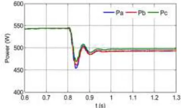
Fig. 12. Power injected to the grid with modulation compensation
S = 1000 W/m2, and every phase is generating a maximum power of 555 W. After t = 0.8 s, the power harvested from phase a decreases to 400
W, and those from the other two
phases stay the same. Obviously, the power supplied to the three-phase grid-connected inverter is unbalanced. However, by applying the modulation compensation scheme, the power injected to the grid is still balanced, as shown in Fig. 12. In addition, by comparing the total power extracted from the PV panels with the total power injected to the grid, it can be seen that there is no extra power loss caused by the modulation
compensation scheme.
Fig. 13 shows the output voltages (v j N) of the three-phase inverter. Due to the injected zero sequence component, they are unbalanced after t
Fig. 13. Three-phase inverter output voltage waveforms with modulation
compensation.
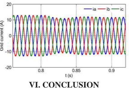
VI. CONCLUSION
In this paper, Fuzzy based P and O MPPT is illustared . The multilevel inverter topology will help to improve the utilization of connected PV modules if the voltages of the separate dc links are controlled independently. Thus, a distributed MPPT control scheme for both single- and three-phase PV systems has been applied to increase the overall efficiency of PV systems. For the three-phase grid-connected PV system, PV mismatches may introduce unbalanced supplied power, resulting in unbalanced injected grid current. A modulation compensation scheme, which will not increase the complexity of the control system or cause extra power loss, is added to balance the grid current. A modular three-phase seven-level cascaded H-bridge inverter has been built in the laboratory and tested with PV panels under different partial shading conditions. With the proposed control scheme, each PV module can be operated at its own MPP to maximize the solar energy extraction, and the
three-phase grid current is balanced even with the unbalanced supplied solar power.
REFERENCES
[1] J. M. Carrasco et al., ―Power-electronic systems for the grid integration of renewable energy sources: A survey,‖ IEEE Trans. Ind. Electron., vol. 53, no. 4, pp. 1002–1016, Jun. 2006.
[2] S. B. Kjaer, J. K. Pedersen, and F. Blaabjerg, ―A review of single-phase grid connected inverters for photovoltaic modules,‖ IEEE Trans. Ind. Appl., vol. 41, no. 5, pp. 1292–1306, Sep./Oct. 2005.
[3] M. Meinhardt and G. Cramer, ―Past, present and future of grid connected photovoltaic- and hybrid power-systems,‖ in Proc. IEEE PES Summer Meet., 2000, vol. 2, pp. 1283–1288.
[4] M. Calais, J. Myrzik, T. Spooner, and V. G. Agelidis, ―Inverter for singlephase grid connected photovoltaic systems—An overview,‖ in Proc. IEEE PESC, 2002, vol. 2, pp. 1995–2000.
[5] J. M. A. Myrzik and M. Calais, ―String and module integrated inverters for single-phase grid connected photovoltaic systems—A review,‖ in Proc. IEEE Bologna Power Tech Conf., 2003, vol. 2, pp. 1–8.
[6] F. Schimpf and L. Norum, ―Grid connected converters for photovoltaic, state of the art, ideas for improvement of transformerless inverters,‖ in Proc. NORPIE, Espoo, Finland, Jun. 2008, pp. 1– 6.
[7] B. Liu, S. Duan, and T. Cai, ―Photovoltaic
DC-building-module-based BIPV system—
Concept and design considerations,‖ IEEE Trans. Power Electron., vol. 26, no. 5, pp. 1418–1429, May 2011.
Summer Meet., Seattle, WA, USA, Jul. 2000, pp. 1271–1274.
[9] H. Ertl, J. Kolar, and F. Zach, ―A novel multicell DC–AC converter for applications in renewable energy systems,‖ IEEE Trans. Ind. Electron., vol. 49, no. 5, pp. 1048–1057, Oct. 2002.