MCS HOST INTERFACE LINK HL7
INSTALLATION/CONFIGURATION GUIDE
NEC America, Inc.
LIABILITY DISCLAIMER
NEC America reserves the right to change the specifications, functions, or features in this document at any time without notice. NEC America has prepared this document for use by its employees and customers. The information contained herein is the property of NEC America and shall not be repro-duced without prior written approval from NEC America.
Copyright 1997
NDA-30088 Revision 1.0 Page i
MCS Host Interface Link CONTENTS
TABLE OF CONTENTS
Page
Chapter 1 - HL7 INTERFACE. . . 1
Background. . . 1
Shared Libraries (LLP and Link Type) . . . 1
HL7 Configurations (User Definable) . . . 1
Installation. . . 1
Interface Configuration . . . 1
Shared Library Configuration (LLP and Link Type) . . . 3
Link Specific Parameters Configuration . . . 6
Miscellaneous Configurations (Timers, Counters, Etc.) . . . 8
Page ii NDA-30088 Revision 1.0
CONTENTS MCS Host Interface Link
NDA-30088 Revision 1.0 Page iii
MCS Host Interface Link FIGURES
LIST OF FIGURES
Figure Title Page
1-1 Main Menu. . . 2
1-2 Configuration Menu . . . 3
1-3 Shared Library Selection Menu . . . 3
1-4 Low Level Protocol Selection Menu . . . 4
1-5 Link Type Selection Menu . . . 5
1-6 Shared Library Load Menu . . . 6
1-7 TCP/IP Link Specific Parameters . . . 7
1-8 Asynchronous Serial Link Specific Parameters. . . 8
1-9 Miscellaneous Configurations . . . 9
1-10 HL7 User-Definable Configuration . . . 10
1-11 HL7 Receiving Application Configuration . . . 11
1-12 HL7 Sending Application Configuration. . . 12
Page iv NDA-30088 Revision 1.0
FIGURES MCS Host Interface Link
NDA-30088 Revision 1.0 Page 1
MCS Host Interface Link HL7 INTERFACE
Chapter 1
HL7 INTERFACE
Background
The HL7 interface provided for the MCS supports several communication low level protocols and two physical interface types.
The MCS HL7 interface software has many configurable items that can be tailored for a particular site’s communication link. Background information of these configurable items is described below. For more detailed information on the available options for these fields, refer to the section, Shared Library Configuration (LLP and Link Type) and, Link Specific Parameters Configuration.
Shared Libraries (LLP and Link Type)
The Link Type defines the hardware link to the MCS HL7 interface. Currently, the MCS HL7 interface supports 1) a TCP/IP Ethernet connection, and 2) an
asynchronous, serial line (RS-232) connection. In addition, different selections are available for the Low Level Protocol (LLP). The LLP defines a data encapsulation method to provide flow control and error recovery issues of data transmissions. The installer selects from a menu of shared libraries to define the LLP and Link Type applicable to the site’s communication link. Shared libraries provide a means to dynamically load the needed processing code into the MCS HL7 interface application without the need to have separate interface applications for each site specific communication link.
HL7
Configurations (User Definable)
The HL7 Standard Version document defines some fields as user-definable. For those fields that are applicable to the MCS, a configuration screen is provided to define the values expected in the HL7 message for correct processing of these fields by the MCS HL7 interface application.
Installation
The MCS HL7 interface software is installed using the OAI APM Installation of Applications/Packages command. The installer will need to know the ‘root’
password for the system. After the files have been installed, the installation routine will prompt the installer to configure the MCS HL7 interface software. The configuration process is discussed in the following sections.
Interface Configuration
Configuration of the MCS HL7 interface must be completed before the MCS HL7 interface application can be started. At each administrative login (as the user
mcshost), if the MCS HL7 interface software has not yet been configured, the user
Page 2 NDA-30088 Revision 1.0
HL7 INTERFACE MCS Host Interface Link
Interface Configuration (Cont)
If the MCS HL7 interface software was not configured during the installation of the application, follow steps 1. - 2. to get to the Configuration option display. Otherwise, if configuration is being performed as part of installation, skip to step 3.
1. From the login: prompt enter the user account name mcshost. Enter a password if required.
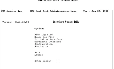
2. If the system has not been previously configured for the MCS HL7 interface, you will be prompted to do so; other-wise the main menu screen (Figure 1-1) will be displayed. To configure the MCS HL7 interface, select the Configura-tion opConfigura-tion from the main menu.
Figure 1-1 Main Menu
3. The Configuration command will display the screen shown in Figure 1-2. This menu displays all configurable items of the MCS HL7 interface application. Select the desired con-figuration option.
NEC America Inc MCS Host Link Administration Menu Tue - Jan 27, 1998
Version: HL71.03.03 Interface Status: Idle
Options
View Log File Erase Log File Initialize Interface Terminate Interface Configuration Statistics
UNIX Logout
NDA-30088 Revision 1.0 Page 3
MCS Host Interface Link HL7 INTERFACE
Figure 1-2 Configuration Menu
Shared Library Configuration (LLP and Link Type)
The shared library configuration options allow the user to select the LLP and / or the Link Type configuration items, and to load these libraries to shared library directory path.
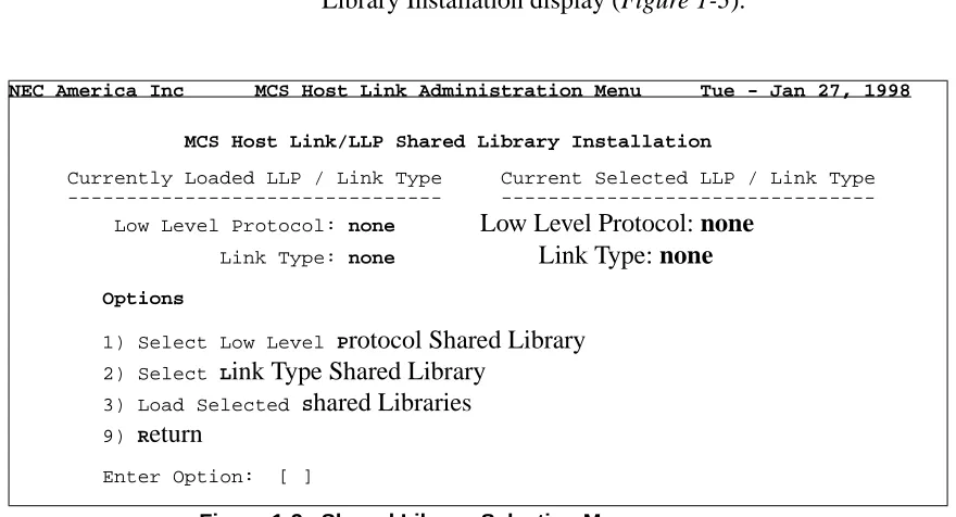
1. Select ‘1’ or ‘S’ to access the MCS Host Link/LLP Shared Library Installation display (Figure 1-3).
Figure 1-3 Shared Library Selection Menu
2. Select ‘1’ or ‘P’ to choose the applicable LLP used by the site. The LLP Shared Library Selection menu screen is dis-played (Figure 1-4).
NEC America Inc MCS Host Link Administration Menu Tue - Jan 27, 1998
MCS Host Interface Configuration
Options
1) Shared Library Configuration (LLP and Link Type) 2) Link Specific Parameters Configuration
3) Misc Configurations (Timers, Counters, Etc.) 4) HL7 Configurations (User Definable)
9) Return
Enter Option: [ ]
NEC America Inc MCS Host Link Administration Menu Tue - Jan 27, 1998
MCS Host Link/LLP Shared Library Installation
Currently Loaded LLP / Link Type Current Selected LLP / Link Type Low Level Protocol: none Low Level Protocol: none
Link Type: none Link Type: none
Options
1) Select Low Level Protocol Shared Library 2) Select Link Type Shared Library
3) Load Selected Shared Libraries 9) Return
Page 4 NDA-30088 Revision 1.0
HL7 INTERFACE MCS Host Interface Link
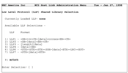
Figure 1-4 Low Level Protocol Selection Menu
Note: The available LLP’s are listed. The format of the LLP signifies the data encapsu-lation of the HL7 message. LLP1 and LLP2 are implementations of the Hybrid Lower Layer Protocol and the Minimal Layer Protocol, respectively, described in the HL7 Version 2.2. Implementation Guide. LLP3, LLP4 and LLP7 are rec-ommended for use with the TCP/IP Link Type, while LLP6 is recrec-ommended for use with the Asynchronous Serial Link Type. For LLP3, ‘{length}’ defines a 4 character length field, equal to the length of the ‘{data}’ portion of the message. For LLP4, ‘<EB>’ is equal to the ASCII <FS> character (1C hex). For LLP6, the <LRC> represents a longitudinal redundancy check byte.
3. The currently loaded LLP value indicates the LLP presently used by the MCS HL7 interface application. A ‘none’ indi-cates the LLP has not yet been configured. Select the appro-priate LLP number, followed by <CR>. The MCS Host Link/LLP Shared Library Installation menu screen is dis-played (Figure 1-3).
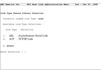
4. Select ‘2’ or ‘L’ to choose the applicable Link Type used by the site. The Link Type Shared Library Selection menu screen is displayed (Figure 1-5).
NEC America Inc MCS Host Link Administration Menu Tue - Jan 27, 1998
Low Level Protocol (LLP) Shared Library Selection
Currently Loaded LLP: none
Available LLP Selections
LLP Format
1) LLP1 - <SB>tvv<CR>{data}ccccxxx<EB><CR> 2) LLP2 - <SB>{data}<EB><CR>
3) LLP3 - {length}{data} 4) LLP4 - {data}<EB>
6) LLP6 - <STX><STX><STX><SOH>{data}<ETX><LRC><EOT> 7) LLP7 - <STX>{data}<ETX>
9) Return
NDA-30088 Revision 1.0 Page 5
MCS Host Interface Link HL7 INTERFACE
Figure 1-5 Link Type Selection Menu
5. The currently loaded Link Type value indicates the Link Type presently used by the MCS HL7 interface application. A ‘none’ indicates the Link Type has not yet been config-ured. Select the ‘1’ or ‘A’ for an Asynchronous Serial Link, or select ‘2’ or ‘T’ for a TCP/IP link, followed by <CR>. The MCS Host Link/LLP Shared Library Installation menu screen is displayed (Figure 1-3).
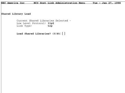
6. If the currently selected LLP / Link Type shown in the upper right portion of the display is correct, select ‘3’ or ‘S’ to load the shared libraries for use with the MCS HL7 interface application. The Shared Library Load screen is displayed (Figure 1-6), showing the configuration chosen, with a prompt to load the libraries.
NEC America Inc MCS Host Link Administration Menu Tue - Jan 27, 1998
Link Type Shared Library Selection
Currently Loaded Link Type: none
Available Link Type Selections
Link Type Definition
1) ASL - Asynchronous Serial Link 2) TCP - TCP/IP Link
9) Return
Page 6 NDA-30088 Revision 1.0
HL7 INTERFACE MCS Host Interface Link
Figure 1-6 Shared Library Load Menu
Note: If the MCS HL7 interface application is currently running, the shared libraries cannot be loaded. If this is the case, the user is notified and prompted to tempo-rarily halt the interface while the shared libraries are loaded.
When complete, the MCS Host Link/LLP Shared Library Installation menu screen is displayed (Figure 1-3). Select ‘9’ or ‘R’ to return to the MCS Host In-terface Configuration screen (Figure 1-2).
Link Specific Parameters Configuration
This menu gives the user different configuration options based on which Link Type was chosen in Section 1.3.1, Shared Library Configuration (LLP and Link Type), step 5.
For TCP/IP Link Type:
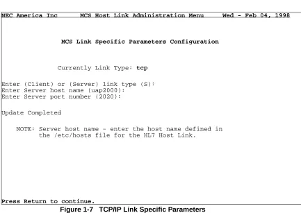
1. Select ‘2’ or ‘L’ to access the MCS Link Specific Parame-ters Configuration display (Figure 1-7).
2. Enter ‘C’ or ‘S’, followed by <CR>, to indicate whether the MCS HL7 interface acts as client or server, respectively, in the client/server model for TCP/IP. In “Server” mode, the applications “listens” for a connection from a client before communications can begin. In “Client” mode, the
NEC America Inc MCS Host Link Administration Menu Tue - Jan 27, 1998
Shared Library Load
Current Shared Libraries Selected Low Level Protocol: llp2
Link Type: tcp
NDA-30088 Revision 1.0 Page 7
MCS Host Interface Link HL7 INTERFACE
Link Specific Parameters Configuration (Cont)
application makes repeated attempts to connect to the server application, and then communications can begin. The cur-rently selected, or default value, is displayed in parenthesis.
Figure 1-7 TCP/IP Link Specific Parameters
3. Enter the server host name, followed by <CR>. For default when “S” or “Server” is selected, the UAP’s host name is shown. However, the value entered must match the host name as defined in the /etc/hosts file corresponding to the IP address used for the HL7 link. If the link type is “C”, the server host name is the name of the Hospital Information System (HIS) machine to which connect requests are being made.
4. Enter the server TCP/IP port number, followed by <CR>. When complete with this step enter <CR> again to return back to the MCS Host Interface Configuration screen (Fig-ure 1-2). For an Asynchronous Serial Link Type:
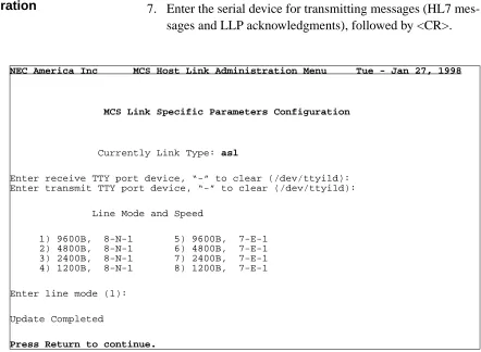
5. Select ‘2’ or ‘L’ to access the MCS Link Specific Parame-ters Configuration display (Figure 1-8).
NEC America Inc MCS Host Link Administration Menu Wed - Feb 04, 1998
MCS Link Specific Parameters Configuration
Currently Link Type: tcp
Enter (Client) or (Server) link type (S): Enter Server host name (uap2000):
Enter Server port number (2020):
Update Completed
NOTE: Server host name - enter the host name defined in the /etc/hosts file for the HL7 Host Link.
Page 8 NDA-30088 Revision 1.0
HL7 INTERFACE MCS Host Interface Link
Link Specific Parameters Configuration (Cont)
6. Enter the serial device for receiving HL7 messages, fol-lowed by <CR>.
7. Enter the serial device for transmitting messages (HL7 mes-sages and LLP acknowledgments), followed by <CR>.
Figure 1-8 Asynchronous Serial Link Specific Parameters
8. Enter the appropriate number indicating the line mode for the link, followed by <CR>. Each line mode displayed indi-cates baud rate, number of bits, parity type, and number of stop bits. When complete with this step enter <CR> again to return back to the MCS Host Interface Configuration screen (Figure 1-2).
Miscellaneous Configurations (Timers, Counters, Etc.)
Figure 1-9 shows the Miscellaneous Configurations menu, which gives
miscellaneous options for configuration. These parameters have default values displayed in parenthesis next to each prompt. The default values are the
recommended values. Modifications to these values should be coordinated with the system administrator.
NEC America Inc MCS Host Link Administration Menu Tue - Jan 27, 1998
MCS Link Specific Parameters Configuration
Currently Link Type: asl
Enter receive TTY port device, “-” to clear (/dev/ttyi1d): Enter transmit TTY port device, “-” to clear (/dev/ttyi1d):
Line Mode and Speed
1) 9600B, 8-N-1 5) 9600B, 7-E-1 2) 4800B, 8-N-1 6) 4800B, 7-E-1 3) 2400B, 8-N-1 7) 2400B, 7-E-1 4) 1200B, 8-N-1 8) 1200B, 7-E-1
Enter line mode (1):
Update Completed
NDA-30088 Revision 1.0 Page 9
MCS Host Interface Link HL7 INTERFACE
Figure 1-9 Miscellaneous Configurations
1. Select ‘3’ or ‘M’ to access the MCS Host Link Miscellaneous Configuration display (Figure 1-9).
2. Enter a time-out value (in seconds) for waiting on a complete message reception, followed by <CR>. If a message recep-tion has begun, and the complete message has not been received by this configured time, the message reception is aborted.
3. If the Link Type chosen is TCP/IP, enter the retry timer value, followed by <CR>. This value defines the time inter-val used to retry a ‘connect’ to the server when the link goes down.
4. Enter the logging level for the MCS HL7 interface applica-tion, followed by <CR>.
5. Enter the shared memory key value, followed by <CR>. The shared memory here is used to share information for collect-ing statistical data about message reception and message processing.
6. Enter the maximum number of negative acknowledgments (NAK) for a single message before terminating the link, fol-lowed by <CR>.
NEC America Inc MCS Host Link Administration Menu Tue - Jan 27, 1998
MCS Host Link Miscellaneous Configuration
Enter the new configuration value or just press Return to accept the current value.
Enter message reception timer value (5 sec):
Enter network (TCP/IP) link connection retry timer value (15 sec): Enter logging level (9 level):
Enter host link shared memory key value (2734):
Enter number of times to send a negative acknowledgment (3): Enter host interface working directory (/oai/app/mcs/host/bin): Enter logging and statistics directory (/oai/app/mcs/host/log): Enter modem dial out telephone number ():
Update Completed
Page 10 NDA-30088 Revision 1.0
HL7 INTERFACE MCS Host Interface Link
Configurations (Timers, Counters, Etc.) (Cont)
7. Enter the directory path for the current working directory, followed by <CR>.
8. Enter the directory path which contains the logging file, fol-lowed by <CR>.
9. If the Link Type chosen is Asynchronous Serial, and if a modem is being used, enter the dial out number, followed by <CR>. When complete with this step enter <CR> again to return back to the MCS Host Interface Configuration screen (Figure 1-2).
HL7
Configurations (User Definable)
Some of the fields defined by the HL7 Standard are allowed to have site-specific values. The values for these ‘user-defined’ fields are configurable using the HL7 Configurations menu. Only those fields applicable to the MCS HL7 interface are available for configuration. The values entered here are compared against incoming HL7 messages. If a match occurs, process-ing is performed accordprocess-ingly.
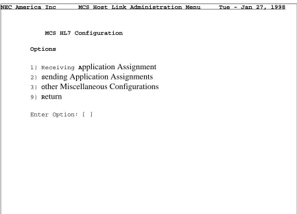
1. Select ‘1’ or “A” to assign the Receiving Application name for HL7 messages (Figure 1-10).
Figure 1-10 HL7 User-Definable Configuration
NEC America Inc MCS Host Link Administration Menu Tue - Jan 27, 1998
MCS HL7 Configuration
Options
1) Receiving Application Assignment 2) Sending Application Assignments 3) Other Miscellaneous Configurations 9) Return
NDA-30088 Revision 1.0 Page 11
MCS Host Interface Link HL7 INTERFACE
HL7
Configurations (User Definable)
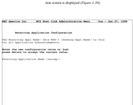
2. Enter the value when prompted (Figure 1-11). If an HL7 message is received with no value entered in MSH-5 (receiving application), this value is used in the MSH-3, Sending Application, field in all HL7 acknowledgments. After entering the data, the HL7 User-Definable Configura-tion screen is displayed (Figure 1-10).
Figure 1-11 HL7 Receiving Application Configuration
3. Select ‘2’ or ‘S’ to enter the Sending Application names allowable for this interface (Figure 1-12). Only HL7 mes-sages with these Sending Application names (MSH-3) are processed. Entering ‘-’ allows all messages to be processed. After entering the data, the HL7 User-Definable Configura-tion screen is displayed (Figure 1-10)
NEC America Inc MCS Host Link Administration Menu Tue - Jan 27, 1998
Receiving Application Configuration
The Receiving Appl Name: Sets MSH-3 (Sending Appl Name) to this for all Application Acknowledgments.
Enter the new configuration value or just press Return to accept the current value.
Page 12 NDA-30088 Revision 1.0
HL7 INTERFACE MCS Host Interface Link
Figure 1-12 HL7 Sending Application Configuration
HL7
Configurations (User Definable) (Cont)
4. Select ‘3’ or ‘O’ to access the MCS HL7 Miscellaneous Configuration display (Figure 1-13).
HL7 Miscellaneous Configurations
NEC America Inc MCS Host Link Administration Menu Tue - Jan 27, 1998
Sending Application Configuration
The Sending Appl Names: Filter list for received messages (MSH-3) (“-” indicates all names are acceptable.
Current Settings:
Sending Appl Names (MSH-3)
NDA-30088 Revision 1.0 Page 13
MCS Host Interface Link HL7 INTERFACE
Figure 1-13 HL7 Sending Application Configuration
HL7
Configurations (User Definable) (Cont)
5. Enter the value used to indicate ‘death’ in the Discharge Disposition field (message segment PV1, sequence 36). 6. For the same field, enter the value to indicate ‘other’ cause
for discharge.
7. Enter the value used to indicate a confidential patient with visitors allowed, as defined in the VIP Indicator field (message segment PV1, sequence 16).
8. For the same field, enter the value to indicate a confidential patient with no visitors allowed.
9. For the same field, enter the value to indicate a non-confi-dential with visitors allowed.
10. For the same field, enter the valued to indicate a non-confi-dential patient, but with no visitors allowed. When complete with this step enter <CR> again to return back to the MCS Host Interface Configuration screen (Figure 1-2).
11. Enter ‘N’ or ‘D’ to indicate whether a new or duplicated Message Control ID (MSH-10) is sent in HL7 acknowledg-ments. If ‘D’ is chosen, the Message Control ID of the received message (MSH-10) is used.
NEC America Inc MCS Host Link Administration Menu Tue - Jan 27, 1998
MCS HL7 Miscellaneous Configuration
Enter the new configuration value or just press Return to accept the current value.
Death Indicator:
Enter HL7 Message Segment Containing Death Indicator (PV1): Discharge Disposition (PV1, Seq 36):
Enter Death Indicator String (Y): VIP Indicator (PV1, Seq 16):
Enter Confidential w/ Visitors Allowed Indicator (Y): Enter Confidential w/o Visitors Allowed Indicator (Y): Enter Visitors Allowed Indicator (N):
Enter No Visitors Allowed Indicator (N): HL7 Application ACK Message Control ID:
HL7 INTERFACE MCS Host Interface Link
Page 14 NDA-30088 Revision 1.0