ISSN (Print) : 2320 – 3765 ISSN (Online): 2278 – 8875
I
nternational
J
ournal of
A
dvanced
R
esearch in
E
lectrical,
E
lectronics and
I
nstrumentation
E
ngineering
(An ISO 3297: 2007 Certified Organization)
Vol. 5, Issue 7, July 2016
Analysis of Basic Telecommunication
Switching Techniques
Akshay Sadashiv Bhoite
Former B.E Student, Dept. of E&TC, Vidya Pratishthan College of Engineering, Baramati, Maharashtra, India
ABSTRACT
:
For communication of voice or data over long distance demands switched telecommunication network.It is a collection of switching elements arranged and controlled in such a way as to setup a communication path between any two distant users so they can communicate more conveniently.
Telecommunication switching networks use basic switching techniques to perform switching which are circuit switching, message switching and packet switching. In circuit switching, when a circuit between source & destination has been established, the packet can be sent and any other packets on the assigned path is denied. In message switching, all switching devices provided with storage. They receive incoming message and store then they forward it according to routing information. In packet switching, a message is broken into packets and these packets are transmitted through the network. This paper presents detail information about the basic switching systems and overview of their functioning, advantages and explains how these techniques overcome on each other's drawbacks.
KEYWORDS: Circuit switching, Message switching, Packet switching, Virtual circuit packet switching, Datagram
packet switching.
I.INTRODUCTION
Modern telecommunication networks carry information signals among entities which are geographically far apart. An entities like a computer, a data terminal, a teleprinter etc. Information transfer between two entities which are very far from each other realised full potential of telecommunication networks. Two entities perform communication through intermediate equipments using the switching system. Telecommunication switching system played vital role in making the idea of "universal connectivity" a reality [1].
ISSN (Print) : 2320 – 3765 ISSN (Online): 2278 – 8875
I
nternational
J
ournal of
A
dvanced
R
esearch in
E
lectrical,
E
lectronics and
I
nstrumentation
E
ngineering
(An ISO 3297: 2007 Certified Organization)
Vol. 5, Issue 7, July 2016
In Fig 1, communication links between each pair of devices, each device can communicate with any other device in network using point to point link. Here is mathematical formula for calculating the number of links
.
Number of links= n (n-1)/2, Where n is Number of devices. As shown in the fig 1, n=4 so, six links are there to form network.
However, mesh topology is impractical for large number of devices. For instance, if we want to connect 3000 devices, then number of links require= 3000(3000-1)/2 that is 4498500 links and if there is 3001 devices then we will require 4501500 links. That means 3000 additional links required to connect extra 1 device. So it is highly impossible to connect large number of devices. A better way is to use switched communication network. In switched network two devices are not directly connected in that they perform communication through intermediate equipments using switching techniques [2].
The switching can be performed using three basic switching techniques. 1. Circuit Switching
2. Message Switching 3. Packet Switching
II.CIRCUIT SWITCHING
Public telephone system is the primary example of circuit switching. Circuit switching was developed during the early days of telephony when calls were connected by operator at a manualswitchboard. In circuit switching channel of fixed bandwidth is dedicated between two users for the duration of a call [3]. It involved following three distinct steps
.
1. Circuit Establishment 2. Data transfer
3. Circuit disconnect
Circuit Establishment
:
Circuit establishes using end to end connection before any transfer of data. As shown in thefig 2 call request sent from source to destination using intermediate switching devices and after the call accept circuit established and it is ready to data transfer
.
Data transfer
:
After call accept data transfer take place from source to destination. Data may be in form of analog ordigital, depending on nature of the network.
Circuit disconnect
:
As shown in the fig 2 after data transfer complete the acknowledgment signal is send back to source and circuit disconnectCircuit switching was developed to handle voice traffic but is now also used for data traffic. It was originally designed and implemented to service analog telephone subscribers but it handles substantial data traffic via modem and gradually being converted to a digital network [4].
ISSN (Print) : 2320 – 3765 ISSN (Online): 2278 – 8875
I
nternational
J
ournal of
A
dvanced
R
esearch in
E
lectrical,
E
lectronics and
I
nstrumentation
E
ngineering
(An ISO 3297: 2007 Certified Organization)
Vol. 5, Issue 7, July 2016
Fig. 2: Timing diagram for circuit switching
Circuit switching has some limitations like circuit establisment and circuitt disconnction introduces extra overhead and delay, there is westage of bandwidth because channel capacity is dedicated for the duration of connection, even if no data transfer and when user not using the bandwidth other cannot use it. It also has several disadvantages for most data applications. First, data transmission is constant it does not allow variable data rate cause link between nodes or switching devices have much higher data rate capability by using TDM and FDM techniques and use transmission media with higher bandwidth. Second, once connection is established, that connection is used throughout the session of conversation even when some other routes can get free in the meanwhile. Third, there is no concept of message priority because it treats all communication requests as equal [5].
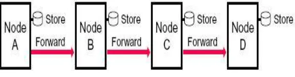
III.MESSAGE SWITCHING
Message switching is an alternative to circuit switching. In message switching technique, it is not required to establish connection between the source and destination [6]. All nodes or switching devices provided with storage. They receive and store the message then they determine the next leg of the route and forward the message. A network using this technique is called a message switching network or store-and-forward network.
ISSN (Print) : 2320 – 3765 ISSN (Online): 2278 – 8875
I
nternational
J
ournal of
A
dvanced
R
esearch in
E
lectrical,
E
lectronics and
I
nstrumentation
E
ngineering
(An ISO 3297: 2007 Certified Organization)
Vol. 5, Issue 7, July 2016
Fig. 3: Message switching
For data transmission message switching is more efficient than circuit switching. The main reason for that is availability of a single channel between two switching devices and that channel is shared by many messages at the same time. In circuit switching channel is dedicated and there is no sharing of a channel therefore message switching technique is more efficient. Another main advantage of message switching is that it is possible to assign different priorities to different messages. So, message with high priorities can forward earlier [6].
In case of large size of message, switches in transit path need enough storage to accommodate entire message otherwise it will monopolizes the link and storage. That is why this message switching concept has been extended to another technique is known as packet switching.
IV. PACKET SWITCHING
Packet switching is one of the effective technologies for long distance data communication. It is used in wide area network, for instance, in the internet. In packet switching data are transmitted in short packets in size of few Kbytes because data transmitted in small size like Kbytes that overcome the disadvantage of message switching. In this technique longer message is broken up into a series of packets and every packet contains some control information in its header and header will contain some information like source address, destination address then sequence number. Such information is needed for routing of packets.
There are two approaches commonly used for handling these packets. 1. Virtual circuit packet switching.
2. Datagram packet switching.
Virtual circuit packet switching: In virtual circuit packet switching a pre-planned route is established before any packet is sent. It is similar to circuit switching that is why it called virtual circuit approach but difference between two approaches is storage and forward method is used in virtual circuit technique. In this technique no dedicated path like circuit switching, only the route is fixed and it is being shared by other source-destination pairs.
ISSN (Print) : 2320 – 3765 ISSN (Online): 2278 – 8875
I
nternational
J
ournal of
A
dvanced
R
esearch in
E
lectrical,
E
lectronics and
I
nstrumentation
E
ngineering
(An ISO 3297: 2007 Certified Organization)
Vol. 5, Issue 7, July 2016
Fig. 4:Virtual circuit packet switching
Datagram packet switching: In datagram packet switching each packet is treated independently. In this approach
switching is done by a switching device or a node which uses a routing table for each incoming packet. Routing table contains a "mapping" of routes to the destination and identifies the outgoing port of a path to the destination [7].
In Fig 5, packet 1 and packet 2 route independently. Both packets take different route to reach destination. Intermediate nodes or switching devices perform routing using routing table.
Fig. 5: Datagram packet switching.
In this technique no call set-up time is required because no call set-up required. So, call set-up phase is avoided. This is best suited for short messages, perhaps better than virtual and circuit switching. Therefore short and burst traffic generated by computers can best be handled using datagram type of packet switching [8]. In case any link is failed then it can be avoided. So, it is more flexible and reliable approach.
V.CONCLUSION
ISSN (Print) : 2320 – 3765 ISSN (Online): 2278 – 8875
I
nternational
J
ournal of
A
dvanced
R
esearch in
E
lectrical,
E
lectronics and
I
nstrumentation
E
ngineering
(An ISO 3297: 2007 Certified Organization)
Vol. 5, Issue 7, July 2016
bandwidth is dedicated between source and destination. So, data transfers at constant rate and introduces constant delay. These features enable circuit switching technique to use for voice communication. This method has limitations like, it treats all transmission as equal so there is no priority among the transmission of data, it introduces extra delay while establishing and disconnecting circuit between source and destination and channel is dedicated so it cannot shared by other user. These limitations are suppressed in technique call message switching.
In message switching, no need to wait for setup of path therefore if a user has data, he or she can transmit it over the channel without any delay. Channel is shared by other messages so channel can be fully utilized and transmission of data takes place according to the priority of data. In case of very large message, device need to have sufficient memory to store the message otherwise it can keep the channel blocked for a long period of time.
In Packet switching, long messages chopped up into small packets and send over the channel so it will not monopolizes the link and storage. Therefore, drawbacks of circuit switching are overcome in message switching and drawbacks of message switching suppressed in packet switching method
.
REFERENCES
[1] Thiagarjan Viswanathan, “Telecommunication Switching Systems and Networks,” PHI Publication, 01-Jan-1992. [2] “Switched Communication Networks” Version 2, CSE IIT, Kharagpur.
[3] TM Chen and DG Messerschmitt, “Integrated Voice/ Data Switching,” IEEE Communications Magazine, vol.26, No.6, pp.19-20, 1988. [4] Brijendra Singh, “Data communication and computer networks,” Fourth edition, PHI Publication, 2014.
[5] Achyut S. Godbole, “Data communications and Networks,” Tata McGraw-Hill Publication, 2002 [6] Ashok Arora, “Foundations of computer science,” Firewall Media Publication, 2006.
[7] Roger L. Freeman, “Telecommunication System Engineering,” John Wiley and Sons, Inc., Publication, 2004.