Provably Secure Concurrent Error Detection
for Advanced Encryption Standard
Xiaofei Guo, Debdeep Mukhopadhyay, and Ramesh Karri Polytechnic Institute of New York University
[email protected], [email protected]
Abstract. Differential fault analysis (DFA) poses a significant threat to Advanced Encryption Standard (AES). Only a single faulty ciphertext is required for contemporary DFA to extract the secret key of AES using an average of230
computations. Concurrent error detection (CED) is widely used to protect AES against DFA. Traditionally, these CEDs are evaluated with uniformly distributed faults, and the resulting fault coverage indicates the security strength of CEDs. However, DFA-exploitable faults are not uniformly distributed and are a small subspace of the entire fault space. We provide a systematic study of various DFAs of AES and experimentally show that in the context of DFA, the attacker is capable ofbiasingthe induced faults to improve the success rate of the attacks. Then we show that the fault coverage of most CED techniques drops significantly against the fault model used by the attacker. This work challenges the traditional use of fault coverage for uniformly distributed faults as a metric for evaluating security against DFA. Good cryptographic designs always consider the worst scenario. Because a single carefully injected fault can leak the secret key, we propose a DFA-aware design flow for CEDs. We point out that CEDs should provide 100% fault coverage for DFA-exploitable faults. We show that cryptographic algorithm-specific CEDs have higher fault coverage against DFA faults and lower area overhead compared to general CEDs.
1
Introduction
Security is only as strong as its weakest link. In addressing the security requirements of various information disciplines, e.g., networking, telecommunications, database systems, and mobile applications, applied cryptography has recently gained immense importance. To satisfy the high throughput requirements of such applications, cryptographic systems are imple-mented either as cryptographic accelerators, or as cryptographic libraries. The complexity of these hardware and software implementations is raising concerns regarding their security and reliability.
Advanced Encryption Standard (AES) is the standard secret key algorithm [46]. To provide high security features, AES implementations have been employed in an increasing number of consumer products with dedicated hardware; e.g., smart cards, servers, FPGAs, and TV set-top boxes. Because the AES algorithm is public, it is subject to continuous, vigilant, expert cryptanalysis. Purely mathematical attacks, such as linear and differential cryptanalysis, reduce the key search space, but they cannot break AES [26].
Although AES is difficult to break mathematically, its hardware implementation, unless carefully designed, may result in security vulnerabilities. Because an attacker can inject malicious faults into a cryptographic device and build correlations between the faulty and the corresponding fault-free outputs, he is able to drastically reduce the key search space and extract the key in a short time. This is known as differential fault analysis (DFA). Radiation, heat, incorrect voltages, and atypical clock rates all cause cryptographic devices to malfunction [7]. DFA of Data Encryption Standard (DES) and other symmetric block ciphers are demonstrated in [11]. Later, DFA of AES has been studied extensively [12,20,42,44,48–50,57]. In recent years, DFA has been demonstrated to be practical, and inexpensive [7, 8, 19, 27]. Optical fault injection attack employed a $30 camera flashgun and a microscope to demonstrate its effectiveness on widely used smart cards [24, 55]. Several DFAs of AES have been shown by injecting clock glitches [2, 6, 50]; such shortening causes multiple errors, corrupting a single byte or multiple bytes. An attacker can also inject transient faults by lowering the supply voltage or injecting power glitches. This methodology is reported to be effective on ASIC implementations of AES [9, 54], as well as FPGA implementations [16, 31]. Varying the operating temperature may also inject controlled faults [8]. The attackers may also inject faults with more costly schemes, including shooting lasers [1, 15, 16] or applying electromagnetic pulse [18].
modules in FIPS 140 [47]. FIPS 140 defines four levels of security. At security level 4, the highest, the protection circuitry shall either (1) shut down the module to prevent further operation or (2) immediately zeroize all plaintexts and secret keys. Because faults can be detected using concurrent error detection (CED) [34], it is used for both reliability and security purposes.
Various CEDs have been proposed [10, 13, 16, 17, 21, 22, 25, 28, 29, 36–38, 40, 43, 45, 52, 58]. Traditionally, the fault coverage is derived from uniformly distributed transient and permanent faults. Although the fault coverage in these papers indicates reliability, it is also used to indicate the security against DFA. Recent literature highlights that the probability of successful attacks is enhanced when attackers bias the fault [23, 60]. Researchers have compared CEDs for their fault coverage [39, 40]; however, these analyses lack discussions on the DFA fault models and the actual ability of attackers. Therefore, re-analysis of the security of CEDs is important. In this paper, we present a comprehensive analysis of the DFAs of AES and show that the DFA faults are a small subspace of the entire fault space. We show that DFA faults drastically reduce the fault coverage previously reported for CEDs. We present fault injection results to show that an attacker is capable of injecting biased faults, as opposed to uniform fault distribution in most previously reported CED designs. We also analyze the other fault injection techniques to evaluate the attacker’s ability.
Note that most DFAs focus on the AES datapath. DFA of the AES key schedule is proposed in [5, 33, 49, 56]. State machine validation and duplication techniques can be used to protect the key schedule unit with low overhead [38]. Thus, we do not focus on these DFAs. Most of the DFAs focus on AES-128 datapath. Although several attacks are proposed for the AES-192 and AES-256 datapath [4, 32, 51], the discussion in this paper will hold true because the fault coverage does not depend on the number of rounds. Fault sensitivity analysis exploits the fact that the delays of different input to output paths is different [35]. It builds a correlation between the hamming weight of the input and the delay characteristics. Although this attack injects faults into the chip, it does not utilize the value of the faulty output; instead, it uses the timing side channel information provided by faults. Thus, this attack is out of the scope of this paper.
1.1 Contributions
In this paper, we provide a systematic study of CEDs with the actual DFAs in perspective. Our key contributions are summarized as follows:
– We systematically analyze all DFAs of AES and their underlying fault models to identify the fault space which can be exploited in a fault attack.
– We analyze the fault coverage of CEDs against DFA, considering the practical fault injection ability of an attacker.
– We propose a CED design flow for AES which takes DFA as a first order consideration. We emphasize that design for the worst case scenario is important for cryptographic devices. Therefore, CEDs should detect 100% DFA faults. The rest of the paper is organized as follows: In Section 2, we introduce the AES algorithm, DFA attack procedure, and CED techniques. In Section 3, we summarize the fault models in previous DFA of AES and find out their internal relationships. In Section 4, we analyze the security of CEDs against DFA. In Section 5, we conclude the paper.
2
Preliminaries
2.1 AES Algorithm
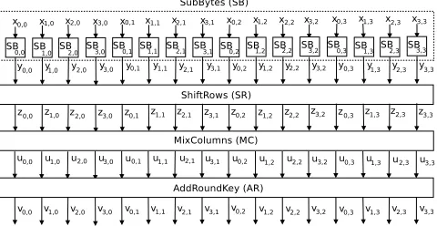
AES is a block cipher with key lengths of 128, 192, and 256. We consider 128-bit key for AES, but the conclusions apply to the other key sizes. AES encrypts a 128-bit plaintext into a 128-bit ciphertext with a 128-bit user key using 10 nearly identical rounds plus an initial round (round 0). One AES encryption round consists of SubBytes, ShiftRows, MixColumns, and AddRoundKey denoted bySB,SR,M C, andAR, respectively, as shown in Fig. 1. In round 0, only AddRoundKey is used and in round 10, MixColumns is not used. Each operation in every round acts on a 128-bit inputstate, where each state element is a byte inGF(28). Each byte is denoted bys
r,c(0 ≤ r, c ≤3) indicating that this byte is in rowrand columncin the state matrix.
s0,0s0,1s0,2s0,3
s1,0s1,1s1,2s1,3
s2,0s2,1s2,2s2,3
s3,0s3,1s3,2s3,3
Fig. 1: One typical AES encryption round (The last round does not have MixColumns).
In SubBytes, each byte is processed by an S-box (SB in Fig. 1). Each SB performs a nonlinear transformation of the input byte. IfXis the input, the output is:
Y =SB(X) =SB([xr,c]r,c=0..3) = [yr,c]r,c=0..3 (2)
In ShiftRows, each row of the state is shifted cyclically byte-wise using a different offset. Row 0 is not shifted, while rows 1, 2, and 3 are cyclically shifted to the left by one, two, and three bytes respectively. The resulting output is:
Z =SR(Y) =
y0,0y0,1y0,2y0,3
y1,1y1,2y1,3y1,0
y2,2y2,3y2,0y2,1
y3,3y3,0y3,1y3,2
= [yr,(r+c)mod4]r,c=0..3= [zr,c]r,c=0..3 (3)
In MixColumns, the output state is obtained by multiplying the output of ShiftRows by a constant matrix. The resulting output is:
U =M C(Z) = [ur,c]r,c=0..3
=
02 03 01 01 01 02 03 01 01 01 02 03 03 01 01 02
z0,0z0,1z0,2z0,3
z1,0z1,1z1,2z1,3
z2,0z2,1z2,2z2,3
z3,0z3,1z3,2z3,3
(4)
In AddRoundKey, the round keyK = [kr,c]r,c=0..3is added (modulo-2) to the 128-bit stateU. The resulting round
output is:
V =AR(K, U) = [kr,c]r,c=0..3+ [ur,c]r,c=0..3= [vr,c]r,c=0..3 (5)
2.2 Differential Fault Analysis
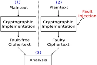
There is a considerable amount of work on DFA of AES. Some of the DFA proposals are based on theoretical models [12, 20, 42, 44, 48–50, 57], while others launched successful attacks on ASIC and FPGA devices using previously proposed theoretical models [2, 9, 16, 18, 31, 50, 54]. The key idea of DFA is composed of three steps as shown in Fig. 2. (1) Run the cryptographic algorithm and obtain fault-free ciphertexts. (2) Inject faults, i.e., unexpected environmental conditions into cryptographic implementations, rerun the algorithm with the same input, and obtain faulty ciphertexts. (3) Analyze the relationship between the fault-free and faulty ciphertexts to significantly reduce the key search space.
Fig. 2: Three steps of DFA.
2.3 Concurrent Error Detection
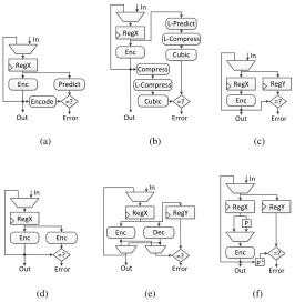
Previous work on CEDs can be classified into four types of redundancy: information, time, hardware, and hybrid, as shown in Fig. 3.
Information Redundancy Many CEDs are based on error detecting codes. In these techniques, the input message is encoded to generate a few check bits, and these bits are propagated along with the input message. The information is validated when the output message is generated as shown in Fig. a. Three information redundancy techniques are discussed below:
Parity-1 One can use single bit parity for the entire 128-bit state, and the parity bit is checked once for the entire round [58].
Parity-16 One parity bit can be generated for each input byte. While some parity-16 techniques depend on the S-box
implementations [10, 43], a general parity formation is proposed in [36]. While gaining higher fault coverage, the area overhead of Parity-16 is more than Parity-1.
Robust Code The parity code suffers from nonuniform fault coverage [28], e.g., parity-1 cannot detect an even number of
faulty bits, and parity-16 cannot detect an even number of faulty bits in each byte. Robust code addresses the limitation of parity code, because it provides uniform fault coverage for all types of faults [28]. The key idea is to construct a prediction circuit at round input to predict a nonlinear property of the round output as shown in Fig. b. The prediction circuit is composed of a linear predictor (L-Predict), linear compressor (L-Compress), and a cubic function (Cubic), where each is the next stage of the previous one. The linear predictor will take the round key and the round input and generate a 32-bit output. The linear compressor and cubic function will reduce the 32-bit data into 28 bits. There are three components at the round output to extract the nonlinear property of the output: the compressor (Compress), the linear compressor, and the cubic function. Each byte of the compressor outputL(j)is equivalent to the componentwise XOR of four bytes of the same column. The output of the linear predictorLl(j)is the same as the output of the compressor. A detailed description of this technique is in [28].
Time Redundancy The function is computed twice with the same input, and the results are compared with each other as shown in Fig. c. One redundant encryption cycle is required to check each round. Although time redundancy has low area overhead, it cannot detect permanent and transient faults that appear in both normal and the redundant computations.
Straightforward Recomputation A time redundancy is proposed in [40]. The design simply recomputes the input and no
hardware change is required.
DDR CED : A variation of the time redundancy is proposed in [38]. The function is computed on both clock edges to speed
RegX Enc Predict Encode In Out =? Error (a) RegX Enc Cubic Compress In Out =? Error L-Predict L-Compress L-Compress Cubic (b) RegX Enc In Out =? Error RegY (c) RegX Enc Enc In Out =? Error (d) RegX Enc Dec In Out =? Error RegY (e) RegX Enc In Out =? Error RegY P P-1 (f)
Fig. 3: Four CEDs. (a) Information redundancy: parity. (b) Information redundancy: robust code. (c) Time redundancy. (d) Hardware redundancy. (e) Hybrid redundancy: inverse function. (f) Hybrid redundancy: invariance-based CED.
Hardware Redundancy The original circuit is duplicated, and both original and duplicated circuits are fed with the same inputs and the outputs are compared with each other as shown in Fig. d. Hardware redundancy technique offers high fault coverage against both naturally occurring faults [40], but it may be bypassed by an attacker who can inject the same faults in both copies of the hardware. Layout obfuscation can be used to confuse the attacker and thus reduce the probability of injecting the same fault [25]. However, both techniques have 100% hardware overhead.
Hybrid Redundancy Hybrid redundancy techniques combine the characteristics of the previous CED categories, and they often explore certain properties in the underlying algorithm and/or implementation.
Inverse function : In [29], an operation, a round, or the entire encryption is followed by its inverse, and the results are
compared with the original input. The detail is shown in Fig. e. Most faults are detected, but both encryption and decryption have to be on the chip. If counter mode, cipher feedback mode, or output feedback mode is used, there is no need to implement both encryption and decryption. In this case, the technique suffers from more than 100% area overhead. Low performance and area overhead are achieved by merging the encryption and decryption datapaths [52]. In this technique, both encryption and decryption are deeply pipelined. In encryption, each stage performs a function in one clock cycle, and the inverse function in the next clock cycle. The authors optimize the area by sharing hardware between functions and their inverses.
Invariance-based CED : In [21], redundant rounds are inserted in the encryption. In each redundant round, the input data is
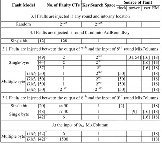
Table 1: A summary of DFA of AES.?CT = ciphertext.†Only one byte in a word is faulty. ‡Two or three bytes in a word are faulty. ♦All four bytes in a word are faulty.
Fault Model No. of Faulty CTs?Key Search Space Source of Fault
clock power laser EM 3.1 Faults are injected in any round and into any location
Random 2128 2128
3.1 Faults are injected in round 0 and into AddRoundKey
Single bit [12] 128 1
3.1 Faults are injected between the output of7thand the input of8thround MixColumns
Single-byte
[49] 2 240 [31, 54] [16] [18]
[44] 2 232 [16] [18]
[57] 1 28 [16] [18]
Multiple byte
DM0 [50] 1 232 [50] [18]
DM1 [50] 1 264 [50] [18]
DM2 [50] 1 296 [50] [18]
DM3 [50] 2128 2128 [50] [18]
3.1 Faults are injected between the output of8thand the input of9thround MixColumns
Single bit [20] ≈50 1 [2] [18]
Single byte [48] ≈40 1 [9] [16] [18]
[42]† 6 1 [16] [18]
At the input of9thMixColumns Multiple byteDM0 [42]
‡
6 1 [18]
DM0 [42]♦ 1500 1 [18]
Recomputing with Shifted Operands In [16], the authors also insert redundant rounds. In each redundant round, the input
data is cyclically shifted, and the order is restored after S-boxes. This technique also has close to 100% fault coverage on S-boxes. However, because the CED for the other three round operations is time redundancy, it suffers the drawback of these these operations.
3
Biased Faults and DFA Fault Models
We first study DFA fault models. Then we formulate the relationships among fault models to identify the DFA fault space. We also show that an attacker can control the fault injection to inflict the targeted faults with a high probability.
3.1 DFA of AES: Fault Models
Faults are Injected in any Round and into any Location The attacker injects faults in any round and any location. These faults are equivalent to naturally occurring random faults. Natural faults may leak information, but the probability is extremely low. First of all, if natural faults do not occur after the7thand before the9thround MixColumns, the attacker cannot use DFA. Secondly, even if the natural faults occur after the7thand before the9thround MixColumns, faults may not last for only one clock cycle. The faulty outputs will not be useful for DFA if faults last for more than one clock cycle. Thirdly, even if faults occur during the right time, they are not exploitable if they do not fit into DFA fault models which we will discuss later. Given the huge uncertainty in time and space, the probability that natural faults are exploitable is minuscule.
Faults are Injected in Round 0 and into AddRoundKey The only fault model an attacker uses in this scenario is single bit transient fault.
Single bit transient fault If the attacker is able to set or reset every bit of the first round key one bit at a time, he can recover
the entire key using 128 faulty ciphertexts with each faulty ciphertext uniquely revealing one key bit [12]. Hence, the key search space is one. Because this attack requires precise control of the fault location and fault value, it becomes impractical even with expensive equipment such as lasers to inject the faults as transistor size scales [1].
Faults are Injected between the Output of7thand the Input of8thMixColumns The attacker uses single and multiple byte fault in this scenario.
Single byte transient fault The three attacks are shown in Table 1. In the first DFA [49], two faulty ciphertexts are needed
to obtain the key with240key search space. This fault model is experimentally verified in [31, 54]. In [54], power glitch is
used to inject faults into a smart card. In the second DFA [44], two faulty ciphertexts are needed to reveal the key. Because this attack exploits the faults more efficiently, the key search space is232. The attack in [57] is similar to [44], but further
improved. The key search space is reduced to only28with a single faulty ciphertext.
Multiple byte transient fault Diagonal fault modelis proposed in [50]. The authors divide the AES state matrix into four
diagonals.A diagonalis a set of four bytes of the state matrix, where theithdiagonal is defined as follows:
Di={sj,(j+i)mod4; 0≤j <4} (6)
We obtain the following four diagonals.
D0= (s0,0, s1,1, s2,2, s3,3), D1= (s0,1, s1,2, s2,3, s3,0),
D2= (s0,2, s1,3, s2,0, s3,1), D3= (s0,3, s1,0, s2,1, s3,2)
Faults in the diagonal fault model are denoted asDMd. They affectddiagonals of the state matrix (1≤d≤4). This model is further classified into four submodels:
1. DM0(i): Faults affectibyte(s) of one diagonal (1≤i≤4).
2. DM1(i,j): Faults affect at most two diagonals; One withifaulty bytes and the other withj(1≤i, j≤4).
3. DM2(i,j,k): Faults affect at most three diagonals, where the faulty diagonals havei,jandkfaulty bytes, respectively (1≤i, j, k≤4).
4. DM3(i,j,k,l): Faults affect at most four diagonals, where the faulty diagonals havei,j,k,l faulty bytes, respectively (1≤i, j, k, l≤4).
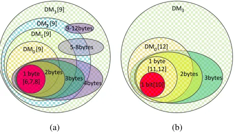
Fig. 4 shows four examples. From left to right areDM0(2),DM1(2,2),DM2(2,2,2), andDM3(2,2,2,1). For each diagonal affected, faults propagate to different columns as shown in Fig. 5. If faults are injected into one, two, or three diagonals, the key search space is reduced to232,264, or296, respectively. If faults are injected into four diagonals, the attacker is not able to do better than brute force.
Fig. 4: Diagonal fault models. The first is aDM0(2) example. Two bytes inD0 are affected. The second is a DM (2,2) 1
example. Two bytes inD0and two bytes inD3are affected. The third is aDM (2,2,2)
2 example. The last is aDM (2,2,2,1) 3
example; all four diagonals are affected.
Fig. 5: Propagation of diagonal faults. The upper row shows the diagonals that faults are injected into. The lower row shows the corresponding columns affected.
Single bit transient fault In [20], the attacker needs only three faulty ciphertexts to succeed with a probability of 97%. The
key search space is trivial.
Single byte transient fault In [48], the authors are able to obtain the key with 40 faulty ciphertexts, and the key is uniquely
revealed.
Multiple byte transient fault Another DFA injects faults into a 32-bit word [42]. The authors propose two fault models.
In the first, the number of faulty bytes can be one, two, or three. It includes the single byte fault model. If only one single byte fault is injected, six faulty ciphertexts are required to reveal the secret key. The second fault model does not require the knowledge of the number of faulty bytes. However, it requires around 1,500 faulty ciphertexts. These uniquely reveal the key.
3.2 Relationships between Fault Models
DFAs exploit a subset of faults, namely single bit, single byte, and multiple byte transient faults injected in selected rounds and into selected locations. Therefore, understanding the relationships among fault models is the basis for analyzing the security of CEDs. Because DFAs target the last few rounds1, we synthesize the relationships between different fault models based on the rounds and the locations they are injected into. The goal is to identify the fault space for which 100% fault coverage is necessary.
Faults are Injected in any Round and into any Location As previously shown, the attacker cannot derive enough useful information from the faults.
DM [9]
DM [9] DM [9]
DM [9]
2bytes 3bytes
4bytes 5-8bytes 9-12bytes
1 byte [6,7,8]
3
2 2
0 1
(a)
DM
3bytes DM [12]
1 byte [11,12]
1 bit[10]
2bytes
3
0
(b)
Fig. 6: Relationships between DFA fault models when faults are injected between (a) the output of7thand the input of8th
round MixColumns, (b) output of8thand the input of9thround MixColumns.
Faults Are Injected between the Output of7thand the Input of8thMixColumns Fig. a shows the relationships among DFA fault models in this category. Single byte faults are, a subset of theDM0faults which are a subset of theDM1faults
and so on. This is summarized as below:
Single Byte⊂DM0⊂DM1⊂DM2⊂DM3 (7)
A more careful look reveals that two byte faults are eitherDM0 or DM1. Three byte faults are eitherDM0,DM1, or
DM2. Four byte faults are eitherDM0,DM1,DM2, orDM3. Similarly, the relationships among five to 12 byte faults and
diagonal fault models are show in Fig a.
Such an analysis of the fault classes will enable one to clearly determine the capabilities of CEDs. As shown in Fig. a,DM3includes all possible transient faults. DFA based onDM0,DM1, orDM2leads to the successful retrieval of the
key [50] . Remember thatDM3faults are the universe of all possible transient faults injected in the selected AES round.
These faults spread across all diagonals and are not exploitable by DFA, as mentioned in Section 3.1. These fault models are multiple byte transient faults and thus, attacks based on these models are more feasible than those based on single byte transient faults. The fault models are exploitable by DFA in the following order: (i)DM0faults reduce the key search space
to232, (ii)DM1faults reduce the key search space to264, and (iii)DM2faults reduce the key search space to296after a
single fault injection. The more encompassing the fault model is, the easier the attacks are. Considering the cardinalities of the identified fault classes, the number of possibleDM0,DM1, andDM2faults are234,3×265, and298, respectively.
DM3has2128possible faults2. If all faults are equiprobable, the probability of injectingDM0,DM1, andDM2faults is
negligible. The probability that a randomly injected fault is aDM0,DM1, orDM2type fault is2−94,13×2−63, and2−30,
respectively.
Faults Are Injected between the Output of8th and the Input of9th MixColumns Fig. b shows the relationships among DFA fault models. Single bit faults are a subset of single byte faults which are a subset ofDM0faults.
3.3 Injecting Biased Faults
Because DFA attackers do not inject uniformly distributed faults, they characterize the device and inject biased faults to achieve high success rates. In this section, we present a case study of fault injection through a laboratory set-up and analyze the other fault injection cases.
Fig. 7: Fault injection set-up using clock glitches.
72
72.472.873.273.67474.474.875.275.67676.476.877.277.67878.478.879.279.680 Clock Frequency
0.1 0.2 0.3 0.4 0.5 0.6 0.7 0.8 0.9 1
Probability of injecting the same fault
DM0(1)
DM1(1,1)
DM1 (1,2)
DM1(1,3)
DM2(1,1,2)
DM2(1,1,3)
Fig. 8: Probability of repeating the same faults when clock frequency changes.
Clock We launched a fault attack with laboratory set-ups as shown in Fig. 7. The set-up included a function generator hooked up to a Xilinx Spartan-3E FPGA on which the AES ran.Slow Clockhad the normal clock frequency of the design. When the8thround encryption started, the device switched to theFast Clockbefore returning to the normal clock frequency, creating critical path violations inside the circuit. We used ChipScope Pro 10.1 analyzer [59] to observe the faulty bytes in the AES. The experiment started with a fast clock frequency set to 72MHz. This frequency was gradually increased at the rate 0.2MHz per step. At each step, we performed 512 fault injections.
The general observations are summarized as follows:
– At the beginning of the fault injection, we injected single byte faults that can be exploited by the attacks proposed in [44, 49, 50].
– When the system was highly overclocked,DM3faults dominated. These faults were not exploitable by DFA. – Between the two extremes discussed above,DM0,DM1, andDM2faults were injected.
Fig. 8 shows the repeatability of faults. The first fault appears when the fast clock is 72.6MHz, although onlyDM1(1) faults are observed when clock frequency is lower than 73.8MHz. The experiment was continued with up to 80MHz, and we observed that the probability of acquiring a sample belonging to a particular fault model is not uniform. For example, in most cases, the faults belong toDM0(1)(black),DM1(1,1)(blue), andDM1(1,2)(red) for which the attacks reduce the key space to28,216, and224, respectively. The highest probability of repeatingDM(1)
0 ,DM
(1,1)
1 , andDM (1,2)
1 faults is 44%,
38.5%, and 72%, respectively. Experiments show that the same faults can be reproduced, thus showing that attackers can inject DFA faults deliberately.
Clock glitch injection is also used in [2]. The authors validated a single bit attack on a Xilinx 3AN FPGA. The proba-bility injecting this kind of fault was 90%.
65nm ASIC chip. 39,881 faulty ciphertexts were collected, and 30,386 were the outcome of single byte faults. Thus, it has 76% probability to inject DFA faults.
Laser In [15], attackers targeted a Xilinx Virtex-2 device. He modified in average of 2.35 bits and 1.99 bits, with 40 µmand 8µmlaser spots, respectively. The probability of modifying CLB contents on the FPGAs ranged from 99.15% to 100% depending on the laser configuration. Moreover, a similar injection technique was used to target the same FPGA [16]. Attackers were able to inject faults in specific rounds to increase the probability to bypass DDR CED. During 1400 laser shots, 50.2% of the faults led to ciphering errors. and 18.1% were undetected, which means that 36.2% of the effective fault injections were undetected.
EM Pulse In [18], attackers characterized the electromagnetic fault injection effect on an AES FPGA implementation. They divided the FPGA chip into 30×30 positions. They did 1,000 encryptions with the same plaintext for each position. The results were reported on three locations. For the first, second, and third locations, the most sensitive byte is the15th,
11th, and7th, respectively. The probability of injecting single bit and single byte faults in these bytes is (80%, 3%), (0%, 53%), and (15%, 20%), respectively.
In summary, attackers are able to reproduce the faults in high probability in these fault injections techniques.
3.4 Adversary Model VS CED
From the previous analysis, it is obvious that the attacker cannot exploit all kinds of faults. Only single bit, single byte, and multiple byte faults as mentioned above are exploitable.
The strength of the DFA adversary lies in its controllability of faults. Ideally, attackers injects faults of arbitrary nature inside a circuit through various mechanisms. However, when the adversary tries to bypass the CED techniques, he needs to carefully control the faults over temporal and spatial dimensions. It is possible to inject the same faults in a device for a specific duration. It is also possible to inject the same fault in two hardware units with similar layout, although it requires high spatial precision. The comparator is assumed to be fault free. In practice, it may be subjected to clock, power, laser, or EM pulse attack. To defend against clock glitch, one can use WDDL logic style [53]. To defend against power or EM pulse attack, one can use power supply noise detector for the comparator [41]. To defend against laser, one can use shielding [14]. The attacker can characterize a device and perform directed variations in the operating conditions, e.g., clock glitch, to inject DFA faults to extract the key. From a designer’s perspective, we would like to develop countermeasures that detect such faults so that the key is not leaked or prevent reductions in key search space. In the next section, we evaluate CEDs for their ability in detecting DFA faults.
4
DFA-aware CED Design Flow for Cryptographic Device
We analyze the fault coverage of CEDs against DFA faults. Attackers can obtain the secret key with one or two faulty ciphertexts when single or multiple byte transient faults are injected as shown in Table 1. Therefore, CEDs should provide 100% fault coverage for DFA faults, because even a single missed DFA fault can be sufficient to reveal the key, rendering the CED useless.
We propose a DFA-aware CED design flow for cryptographic device as shown in Fig.9. The CED design should first go through the security evaluation (blue) and is evaluated against DFA fault models. When the fault coverage for DFA faults meets the security requirement, the design is sent for reliability evaluation. Depending on the reliability requirement, the designer will decide whether to go through the traditional CED design flow or not. In the traditional CED design flow (white), the CED is evaluated against faults with uniform distribution. Then the fault coverage is used as the quality of the CED. This methodology is widely used for other domains such as microprocessors [34]. However, cryptographic components are critical in achieving security objectives, and security should be the first order consideration. The traditional CED design flow does not take fault injection attack into full consideration.
The benefit of considering the DFA faults are two fold:
Fault Coverage (DFA faults)
Meet security requirement?
CED Design
No
Yes
Any reliability Requirement?
Yes
Fault coverage (Random faults)
No
Implementation Yes
No
Security Evaluation
Reliability Evaluation Meet reliability
requirement?
Fig. 9: DFA-aware CED design flow
– It brings down the cost of CED. Developing a technique with fault coverage of 100% for random faults will be very expensive. Therefore, by prioritizing DFA faults, secure but low cost solutions are also possible.
In this work, fault coverage (FC) is calculated as:
F C = 1− Tundetected Ttotal−Tcorrect
whereTtotalis the total number of fault injections,Tundetectedis the number of fault injections in which faults are excited but not detected, andTcorrectrepresents the number of fault injections in which the faults are not excited.
4.1 Security Analysis of Information Redundancy
Security Analysis of Parity-1 Parity-1 considers one parity bit for the 128-bit state matrix. Apparently, it provides 100% fault coverage against single bit faults. However, the technique cannot detect an even number of faults. The fault coverage is1−50% = 50%. For parity-1, the value of the parity bit is not affected by the location of faults; fault coverage for single and multiple byte faults are equal.
As we discussed in Section 3, an attacker needs only one or two faulty ciphertexts. Therefore, by using parity-1 tech-nique with 50% fault coverage, the attacker defeat parity-1 by at most four experiments.
Security Analysis of Parity-16 Similar to parity-1, parity-16 provides 100% fault coverage for single bit faults. For single byte faults, the probability of detecting a fault is50%, while for multiple byte faults, the fault coverage is:
1−(1−50%)n (8)
wherenis the number of faulty bytes. Obviously this technique is not secure against DFA.
Table 2: Fault coverage of CEDs against random and DFA faults 1 Information redundancy. 2. Time redundancy. 3. Hardware redundancy. 4. Hybrid redundancy. 5. Only one byte in a word is faulty. 6. Two or three bytes in a word are faulty. 7. All four bytes in a word are faulty. 8. This technique provides1−2−56 ≈100%fault coverage. 9. The fault coverage of random fault is1−2−38≈100%. 10. The fault coverage of random fault is1−2−37≈100%. 11. The fault
coverage is for ShiftRows, MixColumns, and AddRoundKey. The fault coverage of DFA for SubBytes is1−2−38≈100%.
CED
Fault coverage
Random
Biased fault
Single bit Single byte Multiple byte Area Throu.
[12] [20] [49] [44] [57] [48] [42]5 [42]6 [42]7 [50] overhead Reduct. DM0DM1 DM2
[58] 50 100 100 50 50 50 50 50 50 50 50 50 50 7.4 6.4
[10] 99.998 100 100 50 50 50 50 50 75– 93.75 50– 75– 87.5– 113.3 32.1 87.5 93.75 99.61 99.98
Info.
[36] 99.998 100 100 50 50 50 50 50 75– 93.75 50– 75– 87.5– 8.2-26.9 ∼0
Red.1 87.5 93.75 99.61 99.98
[43] 99.998 100 100 50 50 50 50 50 75– 93.75 50– 75– 87.5– 43-46.1 20 87.5 93.75 99.61 99.98
[28]8 ≈100 100 100 100 100 100 100 100 89.99 99.6 99.6 99.94 99.936 77 13 Time [40]9 ≈100 99.8 99.8 98.4 98.4 98.4 98.4 98.4 93.6 93.6 93.6 93.6 93.6 ∼0 50 Red.2[38]9 ≈100 99.8 99.8 98.4 98.4 98.4 98.4 98.4 93.6 93.6 93.6 93.6 93.6 36 15-55 H.W. [40]10≈100 99.22 99.22 93.75 93.75 93.75 93.75 93.75 75 75 75 75 75 100.1 ∼0
Red3[25]10≈100 ≈100≈100≈100≈100≈100≈100≈100≈100≈100≈100≈100 ≈100 100.1 ∼0 [29]10≈100 ≈100≈100≈100≈100≈100≈100≈100≈100≈100≈100≈100 ≈100 19-38 24-61 Hyb. [52]10≈100 ≈100≈100≈100≈100≈100≈100≈100≈100≈100≈100≈100 ≈100 24.8 14.5 Red.4[21] 99.999 100 100 100 100 100 100 100 100 100 100 100 100 13.2-27.3 10-50
[16]11≈100 99.8 99.8 98.4 98.4 98.4 98.4 98.4 93.6 93.6 93.6 93.6 93.6 2.7 50
ForDM0, a fault can affect from one to four bytes of data in a diagonal. When four bytes are affected, parity-16 has
the highest fault coverage (93.75%), while the fault of this technique is 50% when only one byte is affected. On average, fault coverage is
Detectable faults
All possible faults =
(C4
4×232−C43×224−C42×216−C41×28)×93.75%
232 +
+C 3
4×224×87.5% +C42×216×75% + 4×28×50% 232
≈93.74%
It is close to the best case fault coverage. But we pointed out, the attacker will aim for faults that escape from the CED. ForDM1 andDM2 faults,nchanges between two to eight and three to 12, respectively. Accordingly, the highest fault
coverage for detectingDM1andDM2faults using parity-16 is 99.61% and 99.98%, respectively. However, the lowest fault
coverage while using parity-16 to detectDM1andDM2faults is 75% and 87.5%, respectively. Accordingly, an attacker
only requires four times to break the secret key if theDM1 faults are carefully crafted. The number of experiments are
eight whileDM2faults are injected.
Security Analysis of Robust Code Robust code is designed to address the nonuniform fault coverage problem in linear code such as parity. By using robust code withrcheck bits, the percentage of undetectable faults is reduced from2−r
to2−2rcompared to the parity code, and it provides uniform fault coverage [3]. In [28],ris 28 because of the hardware overhead is low for the cubic network implementation. The fault coverage is
However, we show that a biased fault injection significantly reduces the fault coverage of robust code. Let the round input beX. Then, the output of ShiftRows isZ, and the output of MixColumns isU. ThereforeL(j) = [ui,j]i=0..3⊕ [ki,j]i=0..3. Assumee0,e1,e2, ande3are the DM0fault in each bytes in the diagonal at the input of ShiftRows which
is equivalent to a column at the input of MixColumns. Ife0⊕e1⊕e2⊕e3 = 0, then the robust code fails. The detailed
explanation is given in the appendix. Hence, the probability of detecting such kind of fault is
1−1/256 = 99.6%
Similarly, we can find out that if the fault affect the same bit position in even number of byte quantities, and these byte quantities move to the same column before MixColumns, then the robust code technique will not detect it.
4.2 Security Analysis of Time Redundancy
We call the computation and the recomputation of each roundRiandR0i, respectively (i ∈ {1,2, ...,10}).Rf represents the faulty round(s). Based on the duration of the faults, we classify the faults into three categories:
Category 1: Only one round is affected. This includes all faults that have a duration of odd number of rounds. For
exam-ple, if the same fault appears for three rounds, it must belong to one of the following sets{R0i−1, Ri, R0i}or{Ri, R0i, Ri+1}
(2 ≤i ≤9). Because the same faults will not be detected in the computation and recomputation of the same round, the faults are either detected inR0i−1 orRi+1. Thus, it is equivalent to faults appear in one round. There are 20 cases, i.e.,
Rf ∈ {R1, R
0
1, R2, R
0
2, ..., R10, R
0
10}. In this category, the fault coverage is 100%.
Category 2: Two rounds are affected and they are the computation of one round and the recomputation of another round,
There are nine cases, i.e.,Rf ∈ {(R 0
1, R2),(R
0
2, R3), ...,(R
0
9, R10)}. In this category, the fault coverage is 100%.
Category 3: Two rounds are affected and they are the computation and recomputation of the same round. There are
10 possible cases, i.e.,Rf ∈ {(R1, R
0
1),(R2, R
0
2), ...,(R10, R
0
10)}. We defineP ras the probability of injecting the same
faults. Then in this category, the fault coverage isP r×0% + (1−P r)×100% = 1−P r×100%. Category 2 and 3 include all the faults that have a duration of even number of rounds and the reason is similar to category 1.
Therefore, there categories includes 20 + 9 + 10 = 39 cases. The overall fault coverage is:
100%×(20/39 + 9/39) + (1−P r)×10/39
= 1−P r×10/39 (9)
With random fault model, the probability of injecting the same faults in two rounds is1/(2128−1). According to (9), the fault coverage for random fault is
1−1/(2128−1))×10/39≈1−10−38
When attackers are able to bias the fault, the probability that he injects a single bit fault in both rounds is1/128×P rDF A, whereP rDF Ais the probability that attackers are able to reproduce the same fault.P rDF Adepends on the fault injection technique. The worse case is whenP rDF Ais one, which means attackers accurately reproduces the fault. A good practice to design a secure cryptographic system is to consider the worse case scenarios [30]. So the fault coverage of single bit fault is
1−1/128×P rDF A×10/39≈1−0.2%×P rDF A≥99.8%
Similarly, the fault coverage for single byte fault is:
1−1/16×P rDF A×10/39≈1−1.6%×P rDF A ≥98.4%
The fault coverage forDM0fault is:
1−1/4×P rDF A×10/39≈1−6.4%×P rDF A≥93.6%
Similarly, the worst case fault coverage forDM1andDM2 faults is 93.6% as well. As shown in Fig. 10, when the
0 0.2 0.4 0.6 0.8 1 PrDFA
0.9 0.92 0.94 0.96 0.98 1 1.02
Fault Coverage Random
Single bit Single byte DM
0
Fig. 10: The relationship between fault coverage and the probability of injecting the same faultP rDF A
significantly from 100% to 93.6%. For single bit and single byte faults, the fault coverage drops to 99.8% and 98.4%, respectively.
As mentioned in Section 3.4, an attacker can tweak the number of cycles faults persist. Therefore, straightforward recomputation are vulnerable in the presence of an attacker, because he can control the fault injection period so that the fault appears in both the computation and recomputation. Although the DDR technique requires significant changes to the AES circuit, the attacker successfully break the DDR CED by injecting faults that persist in both the computation and recomputation. [16].
4.3 Security Analysis of Hardware Redundancy
To break hardware redundancy, the attacker needs to inject the same faults in both hardware copies. In two copies of the hardware, we call one original and the other one duplication. The probability that the same faults appears randomly in both of the copies is:1/(2128−1). Therefore, the fault coverage is1−1/(2128−1)≈100%.
Similar to time redundancy, when the attacker is able to bias the fault, the fault coverage for single bit fault injected by the attacker is:
1−(1/128)×P rDF A≈1−0.78%×P rDF A≥99.22%
The worst case fault coverage of single byte is93.75%. ForDM0,DM1,DM2, the worst fault coverage is 75%.
Hardware redundancy can be hardened by layout obfuscation technique [25]. By permuting the wires between two copies of the hardware, one can create at least256! = 8∗10506different wire sequence in AES. Therefore, it significantly
increase the difficulty of injecting the same fault in both copies of the hardware.
4.4 Security Analysis of Hybrid Redundancy
Security Analysis of Inverse Function Because the algorithmic property of AES, each plaintext and key input pair corresponds to a unique ciphertext. Similarly, this one to one mapping is also true for decryption. Previous works such as [29] and [36] claim that this technique has 100% fault coverage, because if the attacker make the AES generate a faulty ciphertext, the decryption will not generate the correct plaintext. Our analysis shows that the fault coverage is close to 100% even against a DFA attacker. For example, if the attacker is able to flip a single bit at10thround AddRoundKey during encryption, the encryption will generate a faulty output. Then, the attacker flips that bit back at the1stround AddRoundKey during decryption, the decryption will generate the original plaintext. This is possible because theithround in encryption corresponds to the10−ithround in decryption. To generalize this, if a faultF occurs in theithround encryption, the complementary fault valueF can occur at the10−ith round decryption to offset the first fault so that the decryption generate the original plaintext to bypass the detection. Therefore, the fault coverage of inverse function against random faults is1−1/(2128−1). Because the key is not known to the attacker, the attacker needs to guess the value ofFto inject
Fig. 11: Diagonal fault propagation in the invariance-based CED when diagonalD0is faulty.
Security Analysis of the Invariance-based CED In [21], the authors prove that the invariance-based CED provides 100% fault coverage for single bit and single byte faults. We prove that this technique also provides 100% fault coverage for the diagonal faults ofDM0,DM1, andDM2models. An attacker cannot benefit from injectingDM3faults to break the secret
key. Accordingly, we do not include this fault model in our discussion.
In this method, for each AES roundirepresented byA(K,(M(S(B(S))))), byte-permutation ofPexists for the state input of S such that In this technique, the authors discuss that for each AES roundirepresented byA(K,(M(S(B(S))))), at least one byte permutation for the inputSexists such that
AR(K,(M C(SR(SB(S))))) =
P−1(AR(P(K),(M C(SR(SB(P(S))))))) (10)
whereSis the 128-bit state input of roundi,Pis a permutation, andP−1denotes the inverse function ofP. The authors
show that one of the byte permutations is as below:
P1(S) =P1([sr,c]r,c=0..3) =
s0,3s0,0s0,1s0,2
s1,3s1,0s1,1s1,2
s2,3s2,0s2,1s2,2
s3,3s3,0s3,1s3,2
= [sr,(c+3)mod4]r,c=0..3 (11)
P1−1([sr,(c+3)mod4]r,c=0..3) = [sr,c]r,c=0..3 (12)
Theorem 1. For the diagonal fault model, at least one column differs between the original computation and the permuted computation.
Proof. We prove this theorem forDM0,DM1, andDM2 fault models. The theorem holds true forDM3faults too but
since injectingDM3faults are not useful in revealing the secret key, we do not discuss those faults.
Case 1: DM0 faults. Assume that a fault affects only the diagonal ofDj in C1 (the first encryption cycle used for
CED), whereDj = xi,(i+j)mod4 (0 ≤ i ≤ 3,0 ≤ j ≤ 3). Accordingly, Si,(i+j)mod4 generates faulty output(s)
ofyi,(i+j)mod4. After performing ShiftRows, the outputs are[zr,c]r,c=0..3=[yr,(r+c)mod4]r,c=0..3, and the faulty state
elements are[zr,j]r=0..3 =yi,(i+j)mod4. In MixColumns, a fault is propagated from a single faulty input to all the state
elements residing in the same column, i.e.,[ur,j]r=0..3. After AddRoundKey, [vr,j]r=0..3 are the faulty state elements.
However, in C2 (the second encryption cycle used for CED), we useX0 andK0 as the permuted inputs. Using the same steps shown above, faulty state elements are represented as[v0r,j]r=0..3. From equation (12), we know that
[v0r,j]r=0..3= [vr,(j+3)mod4]r=0..3 (13)
Assume that that the faulty column in C1 is the columnj. Considering the above equation, the faulty column in C2 is the column(j+ 3)mod4, where0≤i, j≤3. Therefore,j6= (j+ 3)mod4.
Take Fig. 5 as an example. Assume that in the normal round, diagonalD0is faulty. In C1, after performing SubBytes,
diagonals affected by the faults are different in the two rounds, faults are detected. Therefore, the invariance-based CED changes the diagonal affected by the fault.
Case 2:DM1Faults. Assume that multiple faults affect two diagonals in C1; diagonalsDj1 = xi,(i+j1)mod4 and
Dj2=xi,(i+j2)mod4where0≤i≤3, andj16=j2.
In C1, while performing SubBytes,SBi,(i+j1)mod4andSBi,(i+j2)mod4 generate faulty outputyi,(i+j1)mod4 and
yi,(i+j2)mod4, respectively. After performing ShiftRows, MixColumns, and AddRoundKey, similar to Case 1,[vr,j1]r=0..3
and[vr,j2]r=0..3are the faulty state elements. On the other hand, we apply the permuted inputs in C2. Using the same steps
shown above, faulty state elements are represented as[v0r,j1]r=0..3 and[v
0
r,j2]r=0..3. Therefore, the faulty columns in C1
are the columns ofj1andj2, while the faulty columns in C2 correspond to column(j1 + 3)mod4and(j2 + 3)mod4in C1. Note thatj16= (j1 + 3)mod4andj26= (j2 + 3)mod4. Therefore, the location of the faulty columns in normal and CED-related rounds are different.
As an example, lets0,0,s1,1,s2,2, ands3,3be the state elements of first faulty diagonal. Similarly, assume thats0,1,
s1,2,s2,3, ands3,0are the state elements residing in another faulty diagonal. In C1, after performing AddRoundKey, the
faulty columns are shown as[vr,0]r=0..3and[vr,1]r=0..3. However, in C2, the faulty columns are represented as[v
0 r,0]r=0..3
and[v0r,1]r=0..3, because[v
0
r,0]r=0..3 = [vr,3]r=0..3and[v
0
r,1]r=0..3 = [vr,0]r=0..3. Similar to the case ofDM0, the faulty
columns in C1 and C2 are different.
Case 3:DM2faults. The same proof used for Case 2 can be used for this case.
The invariance-based CED to detectDM0,DM1, andDM2faults, because at least one column of the original and
permutated data states are different. Therefore, the invariance-based CED has 100% fault coverage for single bit, single byte, and diagonal faults.
Security Analysis of the general RESO technique For S-boxes, the fault coverage of the general RESO technique is the same as the the invariance-based CED, because the cyclical shift is a specific form of permutation. Because the cyclical shift is inverse shifted after the S-box, the data are simply computed on the other three operations twice. Therefore, for the other three round operations, the fault coverage will be the same as time redundancy. It is possible that the attacker injects faults in the other three round operations, and the faults persisted in both the computation and recomputation. Therefore, its worst case fault coverage is the same as time redundancy.
We have evaluated the security of CEDs in the presence of DFA. Due to practical concerns, designers have a limited resource to achieve security against DFA. Thus, hardware and computation overheads are important criteria to choose a suitable CED. In the next section, we will analyze the area overhead and throughput reduction of these CEDs.
4.5 Area and Throughput Analysis
The area overhead and the throughput reduction of previously discussed CEDs are shown in Table 2.
Information redundancy allows various trade-off between area and throughput depending on the error detecting codes used. Parity-1 [58] incurs only 7.4% area overhead and 6.4% throughput degradation. Parity-16 in [10] has a significant 113.1% area overhead and 32.1% throughput degradation. This technique replaces the 256×8 memory by the 512×9 memory for each S-box, and therefore the area overhead is significant. Parity-16 in [36] uses a systematic parity formation, and it has around 8.2-26.9% area overhead and almost no performance overhead. Parity-16 in [43] applies to polynomial and normal basis S-box implementations. It has 43-46.1% area overhead and around 20% throughput reduction. Although parity techniques can be implemented with low area overhead and throughput reduction, as mentioned in the previous section, their fault coverage for DFA-exploitable faults are not high. Robust code [28] increase the area by 77% and the throughput drops by 13%. Due to the nonlinear property in robust code, it has the highest fault coverage against DFA attack. Straightforward recomputation [40] requires small changes to the circuit, and thus the area overhead is almost 0%. However, the throughput is halved. DDR CED [38] requires more changes, and thus it has 36% area overhead. Because the DDR CED allows the chip to operate at a higher frequency, the throughput reduction ranges from 15-55% depending on the clock frequency. Both of these techniques are not sufficient for security, because the attacker can inject faults that persist in the computation and recomputation as discussed in Section 4.2.
Inverse function [29] has 19-38% area overhead and 24-61% throughput reduction. These variations depends on whether the CED is implemented at the operation, round, or algorithm level. In cases where counter mode encryption is used, a decryption unit is not in the original chip. Therefore, a decryption unit is added and thus causing a significant increase in area overhead which is around 119-138%. Moreover, if the AES is implemented in composite field, hardware sharing between S-box and inverse S-box is possible to decrease the hardware cost to 24.8% (from 38%) [52]. The reason why they can achieve such a low area overhead is that S-boxes occupy more than half of the implementation area. The invariance-based CED [21] has 13.2-27.3% area overhead and 10-50% throughput reduction. Because it uses an algorithmic property of AES, it is able to provide high fault coverage against DFA-exploitable faults with small area overhead. However, this technique requires AES to be implemented with 128-bit datapath. It will have the same fault detection capability as straightforward recomputation when used in 32-bit or 8-bit AES implementation.
5
Conclusion
DFA is proven to be practical and low-cost. CEDs are used to detect deliberately injected faults. However, previous CED techniques do not differentiate between random and malicious faults. Their claims of security are based on the fault cover-age of uniformly distributed faults. From an attacker’s perspective, only a subset of the fault space is enough for successful attacks.
We proposed a DFA-aware CED design flow which prioritizes the DFA faults. This flow brings two advantages over the traditional flow: (1) It provides an accurate security evaluation of CEDs. (2) It brings the possibility of designing low-cost and secure CEDs. We establish the inter-relationships of various fault models and the type of faults that are possible to inject. With this adversary model, we analyze the security of the most common CEDs. These faults can bypass most CED techniques.
Neither hardware redundancy nor time redundancy guarantees security against a strong adversary. Hardware redun-dancy can be hardened against this kind of adversary by employing layout obfuscation. Information redunredun-dancy techniques offer a large trade-off space. However, parity-based techniques do not provide sufficient protection against DFA. Moreover, the robust code provides high security, but the area overhead is close to hardware redundancy. Hybrid redundancy tech-niques are highly secure and they provide flexible trade-off between security and cost. The area overhead of the inverse function technique is large only if counter mode, cipher feedback mode, or output feedback mode is used. Though the throughput is reduced by at most half, the invariance-based CED provides high security for all DFA-exploitable faults with very low area overhead, and it has no limitation on the mode of operations. But it is not applicable when AES is not imple-mented with 128-bit datapath. Therefore, with security against DFA in mind, designers also need to select the appropriate CEDs for their specific implementations.
Acknowledgment
The authors would like to thank the reviewers for their valuable comments. This material is based upon work supported by the NSF CNS program under grant 0831349.
References
1. Michel Agoyan, Jean-Max Dutertre, Amir-Pasha Mirbaha, David Naccache, Anne-Lise Ribotta, and Assia Tria. How to Flip a Bit? InIOLTS, pages 235–239, 2010.
2. Michel Agoyan, Jean-Max Dutertre, David Naccache, Bruno Robisson, and Assia Tria. When Clocks Fail: On Critical Paths and Clock Faults. InCARDIS, pages 182–193, 2010.
3. Kahraman D. Akdemir, Zhen Wang, Mark Karpovsky, and Berk Sunar. Design of Cryptographic Devices Resilient to Fault Injection Attacks Using Nonlinear Robust Codes.Fault Analysis in Cryptography, pages 171–199, 2012.
4. SkSubidh Ali, Debdeep Mukhopadhyay, and Michael Tunstall. Differential Fault Analysis of AES: Towards Reaching Its Limits. Journal of Cryptographic Engineering, pages 1–25, 2012.
5. Subidh Ali and Debdeep Mukhopadhyay. Differential Fault Analysis of AES-128 Key Schedule Using a Single Multi-byte Fault. In CARDIS, pages 50–64, 2011.
7. H. Bar-El, H. Choukri, D. Naccache, M. Tunstall, and C. Whelan. The Sorcerer’s Apprentice Guide to Fault Attacks. Proceedings of the IEEE, 94(2):370–382, 2006.
8. A. Barenghi, L. Breveglieri, I. Koren, and D. Naccache. Fault Injection Attacks on Cryptographic Devices: Theory, Practice, and Countermeasures.Proceedings of the IEEE, 100(11):3056–3076, 2012.
9. Alessandro Barenghi, Cédric Hocquet, David Bol, François-Xaiver Standaert, Francesco Regazzoni, and Israel Koren. Exploring the Feasibility of Low Cost Fault Injection Attacks on Sub-Threshold Devices through An Example of A 65nm AES Implementation. pages 48–60. in Proc. Workshop RFID Security Privacy, 2011.
10. Guido Bertoni, Luca Breveglieri, Israel Koren, Paolo Maistri, and Vincenzo Piuri. Error Analysis and Detection Procedures for a Hardware Implementation of the Advanced Encryption Standard.IEEE Trans. Computers, 52(4):492–505, 2003.
11. Eli Biham and Adi Shamir. Differential Fault Analysis of Secret Key Cryptosystems.Eurocrypt, 1233:37–51, 1997.
12. Johannes Blömer and Jean-Pierre Seifert. Fault Based Cryptanalysis of the Advanced Encryption Standard (AES). InFC, pages 162–181, 2003.
13. Luca Breveglieri, Israel Koren, and Paolo Maistri. An Operation-Centered Approach to Fault Detection in Symmetric Cryptography Ciphers.IEEE Trans. Computers, 56:635–649, May 2007.
14. S. Briais, J.-M. Cioranesco, J.-L. Danger, S. Guilley, D. Naccache, and T. Porteboeuf. Random Active Shield. InFDTC, pages 103–113, sept. 2012.
15. G. Canivet, J. Clediere, J.B. Ferron, F. Valette, M. Renaudin, and R. Leveugle. Detailed Analyses of Single Laser Shot Effects in the Configuration of a Virtex-II FPGA. InIOLTS, pages 289 –294, july 2008.
16. G. Canivet, P. Maistri, R. Leveugle, J. Clédière, F. Valette, and M. Renaudin. Glitch and Laser Fault Attacks onto a Secure AES Implementation on a SRAM-Based FPGA.Journal of Cryptology, 24, 2011.
17. Y. Chih-Hsu and W. Bing-Fei. Simple Error Detection Methods for Hardware Implementation of Advanced Encryption Standard. IEEE Trans. Computers, 55(6):730–731, 2006.
18. A. Dehbaoui, J. Dutertre, B. Robisson, and A. Tria. Electromagnetic Transient Faults Injection on a Hardware and a Software Implementations of AES. InFDTC, pages 7–15, 2012.
19. Chistophe Giraud and Hugues Thiebeauld. A Survey on Fault Attacks. InCARDIS, pages 159–176, August 2004. 20. Christophe Giraud. DFA on AES. InAES, pages 27–41, 2005.
21. Xiaofei Guo and R. Karri. Invariance-based Concurrent Error Detection for Advanced Encryption Standard. InDAC, pages 573–578, Jun 2012.
22. Xiaofei Guo and R. Karri. Recomputing with Permuted Operands: A Concurrent Error Detection Approach.IEEE Trans. Computer-Aided Design, 32(10):1595–1608, 2013.
23. K. Jarvinen, C. Blondeau, D. Page, and M. Tunstall. Harnessing Biased Faults in Attacks on ECC-Based Signature Schemes. In FDTC, pages 72–82, sept. 2012.
24. J.Markoff. Vulnerability Is Discovered In Security for Smart Cards. New York Times, 2002.
25. M. Joye, P. Manet, and JB. Rigaud. Strengthening Hardware AES Implementations against Fault Attack.IET Information Security, 1:106–110, 2007.
26. A. Kaminsky, M. Kurdziel, and S. Radziszowski. An Overview of Cryptanalysis Research for the Advanced Encryption Standard. InMILCOM, pages 1310–1316, Nov 2010.
27. D. Karaklaji´c, J.-M. Schmidt, and I. Verbauwhede. Hardware Designer’s Guide to Fault Attacks.IEEE Trans. VLSI, 21(12):2295– 2306, 2013.
28. Mark Karpovsky, Konrad J. Kulikowski, and Alexander Taubin. Robust Protection Against Fault-Injection Attacks of Smart Cards Implementing the Advanced Encryption Standard. InDNS, pages 93–101, 2004.
29. Ramesh Karri, Kaijie Wu, P. Mishra, and Y. Kim. Concurrent Error Detection Schemes of Fault Based Side-Channel Cryptanalysis of Symmetric Block Ciphers.IEEE Trans. Computer-Aided Design, 21(12):1509–1517, Dec 2002.
30. Jonathan Katz and Yehuda Lindell. Introduction to Modern Cryptography: Principles and Protocols. Chapman and Hall/CRC, 2007.
31. Farouk Khelil, Mohamed Hamdi, Sylvain Guilley, Jean Luc Danger, and Nidhal Selmane. Fault Analysis Attack on an AES FPGA Implementation. InNTMS, pages 1–5, 2008.
32. Chong Hee Kim. Differential Fault Analysis against AES-192 and AES-256 with Minimal Faults. InFDTC, pages 3–9, aug. 2010. 33. Chong Hee Kim and Jean-Jacques Quisquater. New Differential Fault Analysis on AES Key Schedule: Two Faults Are Enough. In
CARDIS, pages 48–60, 2008.
34. Israel Koren and C. Mani Krishna.Fault-Tolerant Systems. Morgan Kaufmann Publishers Inc., San Francisco, CA, USA, 2007. 35. Yang Li, Kazuo Sakiyama, Shigeto Gomisawa, Toshinori Fukunaga, Junko Takahashi, and Kazuo Ohta. Fault Sensitivity Analysis.
InCHES, pages 320–334, 2010.
36. M. Mozaffari-Kermani and A. Reyhani-Masoleh. Concurrent Structure-Independent Fault Detection Schemes for the Advanced Encryption Standard.IEEE Trans. Computers, 59(5):608–622, 2010.
38. P. Maistri and R. Leveugle. Double-Data-Rate Computation as a Countermeasure against Fault Analysis.IEEE Trans. Computers, 57(11):1528–1539, Nov 2008.
39. Paolo Maistri. Countermeasures against Fault Attacks: the Good, the Bad, and the Ugly. InIOLTS, pages 134–137, Jul 2011. 40. T.G. Malkin, F.-X. Standaert, and Moti Yung. A Comparative Cost/Security Analysis of Fault Attack Countermeasures. InFDTC,
pages 109–123, Sept 2005.
41. C. Metra, L. Schiano, and M. Favalli. Concurrent Detection of Power Supply Noise.IEEE Trans. Reliability, 52(4):469–475, 2003. 42. Amir Moradi, Mohammad T. Manzuri Shalmani, and Mahmoud Salmasizadeh. A Generalized Method of Differential Fault Attack
against AES Cryptosystem. InCHES, pages 91–100, 2006.
43. Mehran Mozaffari-Kermani and Arash Reyhani-Masoleh. A Lightweight High-Performance Fault Detection Scheme for the Ad-vanced Encryption Standard Using Composite Field.IEEE Trans. VLSI Systems, 19(1):85–91, 2011.
44. Debdeep Mukhopadhyay. An Improved Fault Based Attack of the Advanced Encryption Standard. InAFRICACRYPT, pages 421–434, 2009.
45. Giogio Di Natale, Marie-Lisa Flottes, and Bruno Rouzeyre. A Novel Parity Bit Scheme for SBox in AES Circuits. InDDECS, pages 1–5, Apr 2007.
46. National Institute of Stardards and Technology (NIST). Advanced Encryption Standard (AES). http://csrc.nist.gov/publications/ fips/fips197/fips-197.pdf, Nov 2001.
47. National Institute of Stardards and Technology (NIST) Federal Information Processing Standards (FIPS) publication 140-2. Security requirements for cryptographic modules. http://csrc.nist.gov/publications/fips/fips140-2/fips1402.pdf, Mar 2001.
48. G. Letourneux P. Dusart and O. Vivolo. Differential Fault Analysis on AES. InCryptology ePrint Archive, 2003.
49. G. Piret and J.J. Quisquater. A Differential Fault Attack Technique against SPN Structures, with Application to the AES and Khazad. InCHES, pages 77–88, Sept 2003.
50. Dhiman Saha, Debdeep Mukhopadhyay, and Dipanwita Roy Chowdhury. A Diagonal Fault Attack on the Advanced Encryption Standard.IACR Cryptology ePrint Archive, page 581, 2009.
51. K. Sakiyama, Y. Li, K. Ohta, and M. Iwamoto. Information-Theoretic Approach to Optimal Differential Fault Analysis.IEEE Trans. Information Forensics and Security, 7(1):109–120, 2012.
52. Akashi Satoh, Takeshi Sugawara, Naofumi Homma, and Takafumi Aoki. High-Performance Concurrent Error Detection Scheme for AES Hardware. InCHES, pages 100–112, Aug 2008.
53. N. Selmane, S. Bhasin, S. Guilley, T. Graba, and J.-L. Danger. WDDL is Protected against Setup Time Violation Attacks. InFDTC, pages 73–83, sept. 2009.
54. Nidhal Selmane, Sylvain Guilley, and Jean-Luc Danger. Practical Setup Time Violation Attacks on AES. pages 91–96. EDCC, 2008.
55. Sergei P. Skorobogatov and Ross J. Anderson. Optical Fault Induction Attacks. Inproceedings of CHES, pages 2–12, Aug 2002. 56. Junko Takahashi, Toshinori Fukunaga, and Kimihiro Yamakoshi. DFA Mechanism on the AES Key Schedule. InFDTC, pages
62–74, 2007.
57. Michael Tunstall, Debdeep Mukhopadhyay, and Subidh Ali. Differential Fault Analysis of the Advanced Encryption Standard Using a Single Fault. InWISTP, pages 224–233, 2011.
58. Kaijie Wu, Ramesh Karri, G. Kuznetsov, and M. Goessel. Low Cost Concurrent Error Detection for the Advanced Encryption Standard. InITC, pages 1242–1248, Oct 2004.
59. Xilinx. ChipScope Pro. http://www.xilinx.com/support/ documentation/dt_chipscopepro.htm.
6
Appendix: Counterexamples
DM0fault counterexamples for parity-1:Assume the input of the8thround isX. The parity of the input isP arity(X).
Therefore, the parities after SubBytes, ShiftRows, and MixColumns areP arity(Y),P arity(Z), andP arity(U), respec-tively. Because ShiftRows and MixColumns do not change the parity of the state matrix [58],P arity(Y) =P arity(Z) =
P arity(U). The key of this AES round isK. The parity of the key isP arity(K). The predicted output parity isP arity(U)⊕ P arity(K). Because the output of this round isV, the actual output parity isP arity(V). When there is no fault,P arity(V) =
P arity(U)⊕P arity(K). When there is an attacker injects faults into the chip, let the faults affect any even number of bits in one diagonal of the input to MixColumns. The faulty input of MixColumns becomesZf. For this case, the outputs of the MixColumns and AddRoundKey becomeUf andVf. Because changing an even number of bits does not affect the parity, the parity of the faulty input equals the parity of the correct inputP arity(Zf) = P arity(Z). Recall that Mix-Columns does not change the parity of the state matrix [58], thus,P arity(Uf) =P arity(Zf). The output parity of the AddRoundKey then becomesP arity(Vf) =P arity(Uf)⊕P arity(K). BecauseP arity(Zf) =P arity(Z), we know P arity(Vf) = P arity(V). Therefore, parity-1 cannot detect an even number ofDM
0 faults. Similar to the previous
counterexample, if any even number of faults affect multiple diagonals at the input of the MixColumns, the faults will be detected becauseP arity(Zf) =P arity(Z)still holds true.
DM0 fault counterexample for parity-16: Assume the input of the 8th round is [xr,c]r,c=0..3. The parity bits of
the input are[pin
r,c]r,c=0..3. The key input of this AES round is[kr,c]r,c=0..3. The parity bits of the key are[pkr,c]r,c=0..3.
The parity bits of the output of the S-box are[pBr,c]r,c=0..3. ShiftRows only cyclically shifts the parity bits. Therefore, the
output parity bits of the ShiftRows becomes[pSr,c]r,c=0..3= [pr,B(r+c)mod4]r,c=0..3. After MixColumns, the parity becomes [pM
r,c]r,c=0..3. Finally, the predicted parity bits are[pprer,c]r,c=0..3 = [pMr,c]r,c=0..3⊕[pkr,c]r,c=0..3, which matches the actual
parity[pK
r,c]r,c=0..3. An attacker can flip an even number of bits in any number of bytes in the same diagonal. Then the
parity bit of that faulty byte is the same as the fault-free one. Therefore, the countermeasure is successfully defeated. Similarly, if any even number of bits in arbitrary number of output bytes are flipped by the attacker, parity-16 will not detect it.
DM0fault counterexamples for robust code:Let the input of the round beX. Then, the output of ShiftRows isZ,
and the output of the MixColumns isU. ThereforeL(j) = [ui,j]i=0..3⊕[ki,j]i=0..3. Assumee0,e1,e2, ande3are theDM0
fault in each bytes in the diagonal at the input of ShiftRows which is equivalent to a column at the input of MixColumns. If e0⊕e1⊕e2⊕e3= 0, then the robust code fails. The reason is explained as below. The faulty bytes occur at the input of
MixColumns. They arez00,j =z0,j⊕e0,z
0
1,j =z1,j⊕e1,z
0
2,j =z2,j⊕e2, andz
0
3,j =z3,j⊕e3, respectively. From (4),
we know that at the input
[u0i,j]i=0..3= 02·z
0
0,j⊕03·z 0
1,j⊕z 0
2,j⊕z 0
3,j⊕ z00,j ⊕02·z10,j⊕03·z20,j⊕z30,j⊕
z00,j ⊕z01,j ⊕02·z20,j⊕03·z30,j⊕
03·z00,j⊕z10,j⊕z20,j⊕02·z03,j
= 02·z0,j⊕02e0⊕03·z1,j⊕03e1⊕z2,j⊕e2⊕z3,j⊕e3
⊕z0,j⊕e0⊕02·z1,j⊕02e1⊕03·z2,j⊕03e2⊕z3,j ⊕e3
⊕z0,j⊕e0⊕z1,j⊕e1⊕02·z2,j⊕02e2⊕03·z3,j⊕03e3
⊕03·z0,j⊕03e0⊕z1,j⊕e1⊕z2,j⊕e2⊕02·z3,j⊕02e3 =z0,j⊕z1,j⊕z2,j⊕z3,j = [ui,j]i=0..3