Optimization Method of Magnetic Coupling Resonant Wireless
Power Transfer System with Single Relay Coil
Jianpo Li1, *, Yang Lu1, Fuxin Liu2, Baochun Mu3, Ziqi Dong4, Songjun Pan2, and Cong Zheng2
Abstract—In view of the dynamic wireless energy charging of electric vehicles, because of the different types or dynamic changes of carrying capacity, the distance between receiving coil at the chassis of electric vehicles and transmitting coil under the road will change dynamically. The unsuitable distance may make the system keep an under-coupling state and reduce the output power of energy transmission system. To improve the system output power, and a relay coil can be added between transmitting coil and receiving coil. But the system charging state may change from under-coupling state to over-coupling state directly because of the introduction of relay coil, and at the same time, the system may show frequency splitting phenomenon. These problems can be solved by adjusting the position of relay coil, the rotating angle of relay coil, and the load value. The experiment shows that the system output power can be improved obviously by increasing relay coil and suppressing frequency splitting. In order to obtain the optimal parameters about the position, rotation angle of relay coil, and load resistance, a genetic algorithm is introduced to improve the output power. At last, using the optimal system parameters, a magnetic coupling resonant wireless power transmission (MCRWPT) system is designed and manufactured, by which the effectiveness and advantage of this approach are verified by experiments.
1. INTRODUCTION
Wireless power transfer (WPT) is a new technology which can free people from annoying wires. Magnetic coupling resonance (MCR) mode is one of the ways of inductance contactless power transfer (ICPT). This technology is widely concerned because it has broad application prospects [1–3]. Compared with wired charging, the ICPT system makes it possible to charge the electric vehicles wirelessly to avoid safety issues and provide convenience to users. The ICPT system also has potential applications in the field of medical sciences, industrial loading machines, and battery charging.
Although the ICPT system has been applied successfully in electric vehicle charging, it still has many problems and challenges. References [4] and [5] optimize the electrical parameters involved in ICPT system. The presented algorithms can help us choose appropriate coil dimension and electrical parameter to cope with the issue of misalignment tolerance. The detailed analysis of different types of wireless charger topologies in electric vehicle charging applications are presented. The different winding designs for wireless transformer are described and compared [6].
However, it is not enough to optimize the parameters of resonant coil, especially in some specific applications. To increase the transmission distance for a two-coil magnetic coupling wireless power transmission system, a relay coil is placed near the transmitting coil or receiving coil [7–9]. The relay
Received 1 November 2018, Accepted 28 February 2019, Scheduled 3 April 2019 * Corresponding author: Jianpo Li ([email protected]).
1 School of Computer Science, Northeast Electric Power University, Jilin 132012, China. 2 Global Energy Interconnection Group
coil can even be combined with the transmitting coil or receiving coil into a whole. An auxiliary coil is added between the transmitting coil and receiving coil. The relationship between the transmission efficiency and coupling coefficient and the self-resonant frequency of auxiliary coil is discussed in [10].
In view of the influence of azimuth change between the coils on the system transmission performance, the mutual inductance coupling model is built to obtain the relationship between mutual inductance coefficient and transmission power. At the same time, the influence of axial distance, radial distance, and deflection angle on the transmission performance is analysed in [11–13].
In the ICPT system, there are three different situations for power transfer, under-coupling, critical coupling, and over-coupling. When the transmission distance is reduced, the transmission power at the original resonant frequency decreases with the decrease of distance. The transmission power has multiple extreme points, but the transmission power at the resonant frequency is not the system’s maximum value. If the corresponding frequency of each extreme point of the system transmission power is called resonant frequency, a number of resonant frequencies will inevitably exist with the splitting of the transmission power, which is called frequency splitting phenomenon. In [14–16], the equivalent circuit model is used to analyse the frequency splitting phenomenon of two-coil system and three-coil system, and the odd frequency and even frequency are obtained. The critical coupling coefficient that determines the over-coupling region is obtained. Reference [17] proposes a method of asymmetric resonant coils to suppress the frequency splitting of a two-coil system. A transmitting structure for multiple receiving coils is proposed in [18, 19]. Each receiving coil is connected with a different compensation capacitance, and the resonant conditions can be satisfied by dynamically adjusting the distance between receiving coils and transmitting coils.
In this paper, in view of the dynamic wireless energy charging of electric vehicles, because of the different types or the dynamic changes of carrying capacity, the distance between receiving coil at the chassis of electric vehicles and transmitting coil under the road will change dynamically. The unsuitable distance may make the system keep an under-coupling state and reduce the output power of energy transmission system. It is proposed that the system output power can be improved by adding a relay coil between transmitting coil and receiving coil according to the distance between transmitting coil and receiving coil. That is, in a traditional two-coil ICPT system, the positions of transmitting coil and receiving coil are fixed. The introduction of relay coil will improve the output power greatly, but the system charging state may change from under-coupling state to over-coupling state directly, at the same time frequency splitting phenomenon may appear in the system. In addition, considering the different measures to suppress frequency splitting, it is difficult to find the best solution.
In this paper, the frequency splitting phenomenon in an ICPT system is inhibited by rotating the relay coil, adjusting its space position, and changing the load resistance of receiving coil. The system output power is improved accordingly. In order to obtain the above optimal parameters, a genetic algorithm is introduced. At last, using the optimal system parameters, we design a magnetic coupling resonant wireless power transmission (MCRWPT) system.
2. SYSTEM PRINCIPLE AND STRUCTURE ANALYSIS
2.1. Coil Resistance, Self-Inductance and Mutual Inductance Calculation
The coil’s equivalent resistance is composed of an ohmic resistance and a radiation resistance. The radiation resistance is negligible relative to ohmic resistance and load resistance. The coil’s equivalent resistance can be calculated according to formula (1) [20, 21].
R =
ωμ0
2σ l
4πr (1)
The self-inductance of spiral coil is calculated by formula (2).
L=N2rμ0[ln (8r/g)−2] (2)
where ω is the angular frequency; μ0 is a vacuum permeability; σ is the copper conductivity; l is the
length of copper wire;N is the number of coil turns;r is the radius of copper wire;g=k(2a+ 2a×N),
The mutual inductance between coils is closely related to the turn number, coil radius, and the distance between turns. If the resonant coil is a coaxial spiral coil, the mutual inductance between coils is as follows.
M =
⎧ ⎪ ⎪ ⎪ ⎪ ⎪ ⎪ ⎪ ⎨ ⎪ ⎪ ⎪ ⎪ ⎪ ⎪ ⎪ ⎩
μ0πNiNjr2ir2j
2
d2ij+ri2 3
2
rj< ri
μ0πNiNjr2ir2j
2
d2ij+rj2 3
2
rj≥ri
(3)
where the transmission distance between coiliand coil j is dij.
2.2. MCRWPT System with Relay Coil
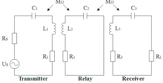
Figure 1 is a structure schematic diagram of MCRWPT system with relay coil. The system includes a driving power, a transmitting coil, a receiving coil, a relay coil, and a load. The transmitting coil is connected with the power supply. The receiving coil is connected with the load. The transmitting coil and relay coil, and also the relay coil and receiving coil are all weakly coupled by magnetic field. The rotation angle θis the angle between the plane of relay coil and the vertical direction to the ground.
Figure 1. Structure schematic diagram of MCRWPT system with relay coil.
The equivalent circuit of MCRWPT system with relay coil is shown in Figure 2.
In Figure 2, Us is the system equivalent voltage. The resistances Rs and RL represent the internal resistance of power supply and load resistance, respectively. The resistances R1, R2, and R3 are the
equivalent resistances of transmitting coil, relay coil, and receiving coil at high frequency, respectively, and R1 =R2 =R3. Their self-inductances areL1, L2, and L3, and L1 = L2 = L3. Their equivalent
capacitances areC1,C2, andC3, andC1 =C2 =C3. The mutual inductance between transmitting coil
and relay coil is M12. The mutual inductance between relay coil and receiving coil isM23. The mutual
inductance M13 between transmitting coil and receiving coil is much smaller than M12 and M23, so it
can be neglected. The current of receiving coil is i3. The system output power is Pout. The angular
frequency is ω. Their coil radii are r1, r2, and r3, respectively, and r1 = r2 = r3. Their turns are N1, N2, andN3, respectively, and N1 = N2 = N3. The distance between transmitting coil and relay coil is d12. The distance between relay coil and receiving coil is d23. The position of the relay coil is represented as ζ =d12/(d12+d23).
Under resonant frequency, the input impedance based on mutual inductance is:
Zin=RS+R1+ (ω0M12)
2
R2+
(ω0M23)2 R3+RL
(4)
The equivalent impedances of transmitting coil, relay coil, and receiving coil are:
Z11=RS+R1+jωL1+
1
jωC1
Z22=R2+jωL2+
1
jωC2
Z33=R3+jωL3+
1
jωC3
+RL
(5)
According to the equivalent circuit, the following KVL equation can be obtained.
Z11i1+jωM12i2 =US Z22i2+jωM12i1+jωM23i3 = 0 Z33i3+jωM23i3 = 0
(6)
In the formula, i1, i2, and i3 are the currents of transmitting coil, relay coil, and receiving coil, respectively.
The system works in resonance state and satisfies formula (7).
ωL1 =
1
ωC1
ωL2 =
1
ωC2
ωL3 =
1
ωC3
(7)
The matrix equation of the resonant state:
Us
0 0
=
Rs+R1 −jωM12 0
−jωM12 R2 −jωM23
0 −jωM23 RL+R3 I 1 I2 I3 (8)
The currents of transmitting coil, relay coil, and receiving coil can be obtained respectively.
I1 = US[ω
2M
232+R2(R3+RL)]
ω2M232(R1+RS) +ω2M122(R3+RL) + (R1+RS)R2(R3+RL) (9) I2 =
ωM12RS(R3+RL)
ω2M232(R1+RS) +ω2M122(R3+RL) + (R1+RS)R2(R3+RL) (10) I3 =
ω2M12M23US
The input power of transmitting coil and the output power of receiving coil are:
Pin =
US2[ω2M232+R2(R3+RL)]
ω2M
232(R1+RS) +ω2M122(R3+RL) + (R1+RS)R2(R3+RL)
(12)
Pout =
ω4M122M232US2RL
[ω2M
232(R1+RS) +ω2M122(R3+RL) + (R1+RS)R2(R3+RL)]
2 (13)
According to η=Pout/Pin, the system transmission efficiency can be further obtained:
η= ω
4M
122M232RL
[ω2M232(R1+RS) +ω2M122(R3+RL) + (R1+RS)R2(R3+RL)][ω2M232+R2(R3+RL)] (14)
3. THEORETICAL ANALYSIS AND DESIGN OF POWER OPTIMIZATION METHOD FOR WPT SYSTEM
3.1. Construction of MCRWPT System in Critical Coupling State
As the mechanical parameters of various resonant coils are known, in order to obtain the maximum output power of MCRWPT system, the optimal position parameters of relay coil, includingζ,d12, and d23 should be known. Under normal circumstances, the internal resistance of power supply R3 is not
equal to that of load RL. The whole system structure is not completely symmetrical, so d12 = d23. That is, the relay coil is not in the middle of transmitting coil and receiving coil. The output power is a function of mutual inductanceM12and mutual inductanceM23, whileM12andM23are the functions of distancesd12and d23, respectively. When the load resistance is known, the optimal mutual inductances
M12 and M23 can be obtained with the output power as the target function. So the distances d12 and
d23 can be obtained respectively in the critical coupling state.
The resonant frequency can be obtained according to formula (7), and formula (11) can be simplified.
I3 =
US M23
M12
(R1+RS) +M12
M23
(R3+RL) +(R1+RS)R2(R3+RL)
ω2M 12M23
(15)
Formula (15) shows that, in order to obtain the maximum output current and the maximum output power, the denominator part should be minimized. So the following two conditions need to be met at the same time.
min
M23
M12(R1+RS) + M12
M23(R3+RL)
min
(R1+RS)R2(R3+RL)
ω2M 12M23
(16)
According to the mean inequality, it can be obtained:
M23
M12(R1+RS) + M12
M23(R3+RL)≥2
(R1+RS)(R3+RL) (17)
If and only if M23
M12(R1+RS) =
M12
M23(R3+RL), it is known that whenM12andM23satisfy formula (18),
the inequality of Eq. (17) is established.
M12=
R1+RS
R3+RLM23 (18)
In addition, in order to minimize (R1+ωR2SM)R2(R3+RL)
12M23 at the same time,M12M23should be maximum.
It is shown thatM12is affected by the inductance of transmitting coil and relay coil, andM23is affected by the inductance of relay coil and receiving coil. That is, according to the principle that coupling coefficientk12≤1,k23≤1, we can get the following conclusions.
M12≤L1L2
M23≤
L2L3
According to the system mechanical parameterRL> RS, so
R1+RS
R3+RL <1,M23> M12. Therefore,
to maximizeM12M23, we can simplify it and bring it into formula (18) and get the new formula (20). M23=
L2L3
M12=
R1+RS R3+RL
M23=
R1+RS R3+RL
L2L3
(20)
When the best mutual inductanceM12 and mutual inductance M23 are obtained, accordingly, the
optimal distances d12 and d23 can be obtained. So, in the critical coupling state, the distance between
transmitting coil and receiving coil is D0 =d12+d23.
3.2. Construction of MCRWPT System in Over-Coupling State
In the MCRWPT system with relay coil mode, the research of suppressing frequency splitting method plays a key role in improving the output power. In order to construct an MCRWPT system in over-coupling state, the method of suppressing frequency splitting is studied. Under the premise of constant mechanical parameters, the distance between transmitting coil and receiving coil D = d12+d23 and
D < D0. At this time, the introduction of relay coil will cause the frequency splitting.
3.3. Study on the Method of Suppressing Frequency Splitting
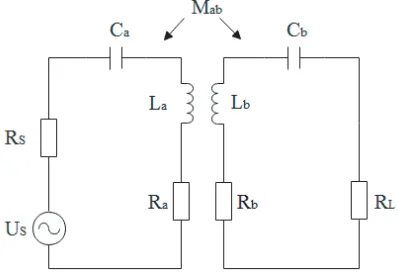
Figure 3 is the equivalent circuit of the traditional two-coil MCRWPT system. According to the method in [21], in order to make the system exit the frequency splitting region, it should satisfy formula (21).
(ωMab)2≤(Rb+RL)2 (21)
Figure 3. Equivalent circuit of the traditional two-coil MCRWPT system.
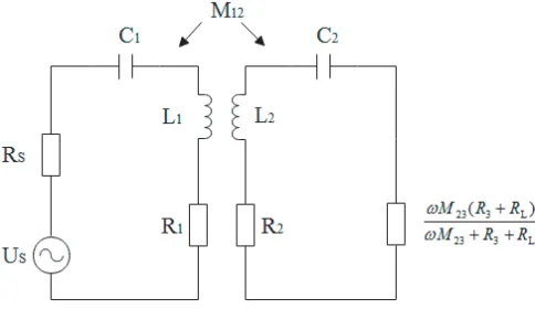
In order to obtain the condition for the MCRWPT system with relay coil to exit frequency split region, the equivalent circuit is simplified to the two-coil structure listed in Figure 4, and formula (22) is obtained.
(ωM12)2 ≤
R2+
ωM23(R3+RL)
ωM23+R3+RL 2
(22)
When the frequency of power supply is stable, and the system mechanical parameters are constant, the frequency splitting can be suppressed by changing M12 andM23, and adjusting the load valueRL.
3.3.1. Rotate the Relay Coil
Figure 4. Equivalent circuit of MCRWPT system with relay coil converting to two-coil MCRWPT system.
The mutual inductance between transmitting coil and relay coil is as follows [22].
M12=μ0√r1r2 π
2−θ
0
(2sin2θ−1)dθ
1− 4r1r2sin
2θ
d122+ (r1+r2)2
(23)
The mutual inductance between relay coil and receiving coil is as follows.
M23=μ0√r2r3 π
2−θ
0
(2sin2θ−1)dθ
1− 4r2r3sin
2θ
d232+ (r2+r3)2
(24)
So the mutual inductances M12 andM23 are the functions of angle θ,θ∈[0,90◦].
3.3.2. Adjust the Position of Relay Coil
Immobilize the rotation angle of relay coil and adjust its position to change the mutual inductanceM12
and M23 so as to suppress the frequency splitting phenomenon. Asζ =d12/D, formulas (23) and (24)
can be converted as:
M12 = μ0√r1r2 π
2−θ0
0
(2sin2θ−1)dθ
1− 4r1r2sin
2θ
ζ2D2+ (r1+r2)2
(25)
M23 = μ0√r2r3 π
2−θ0
0
(2sin2θ−1)dθ
1− 4r2r3sin
2θ
(1−ζ)2D2+ (r2+r3)2
(26)
So mutual inductances M12 and M23 become the functions of ζ,ζ ∈[0,1].
3.3.3. Adjust the Load Resistance
If the rotation angle of relay coil and its position are fixed, the frequency splitting phenomenon can also be suppressed by adjusting the load resistance. According to formula (13), the relationship between load RL and output power Pout can be obtained by taking Pout as objective function and controlling
load value is larger than RLcr, the system will exit the frequency splitting region. By transforming formula (22), we can get RLcr. The condition to withdraw from the frequency splitting region is:
RL≥RLcr= ω
2M12M23−ωM23R2
ω(M23−M12) +R2 −
R3 (27)
3.4. Parameters Optimization Method Based on Genetic Algorithm
The system optimization variables are the location of relay coil ζ, rotation angleθ, and load resistance
RL. So the variable number in genetic algorithm is 3. According to the model of WPT system, the
solution range of optimization variables is set as follows: ζ ∈ [0,1]; θ ∈[0,90◦]; RL ∈[0,1500], unit is
ohm.
In simulation experiments, the accuracy of variable location ζ is 0.1 mm, and its binary number is 7. The accuracy of variable rotation angle is 0.1◦, and the binary number is 10. The accuracy of variable load resistance RL is 0.1 Ω, and its binary number is 9. The population size is 50, and the maximum genetic iteration number is 200.
The initial population is randomly generated. The binary variables are encoded for optimized variables. Their chromosomes are expressed as:
X= [x1 x2 x3] = [ζRLθ] (28) Selection, crossover, and mutation are three genetic factors in basic genetic algorithm. The selection operator makes the chromosomes have higher fitness and more likely to be chosen. Here the selection probability is set to 0.9, so that excellent individuals can be selected from the old population. The new individuals can be obtained by cross operation. Here multipoint cross method is used. The cross probability is set to 0.65. To avoid local premature optimization, the mutation operation is used to ensure genetic diversity. The mutation probability is set to 0.002. The fitness function is formula (13). By genetic iteration, the individuals in new species are decoded, and the best individuals are saved. If it satisfies the requirement, it will output the optimization result. Finally, a set of optimization parameters and maximum output power can be obtained through genetic algorithm.
4. EXPERIMENT AND SIMULATION ANALYSIS
The main system parameters are set as follows. Power supply US = 50 V, internal resistance of power supply RS = 50 Ω, and load value RL = 100 Ω. The winding way and parameters for transmitting coil, relay coil, and receiving coil are all the same. The radius of copper wire a = 0.0445 cm. The coil radius r1 = r2 = r3 = 12 cm. The coil turns N1 = N2 = N3 = 15. The equivalent resistance R1 = R2 = R3 = 3.2794 Ω. The equivalent capacitance C1 = C2 = C3 = 2 ×10⁻¹⁰F. The coil
self-inductanceL1=L2=L3= 1.2577×10⁻⁴H. The resonant frequency is about 10 MHz.
According to the established mechanical parameters, in order to obtain the maximum output power, the specific value of mutual inductances M12 and M23 can be obtained according to formula (20), M12= 3.824×10⁻⁵H,M23= 5.3242×10⁻⁵H. According to formulas (25) and (26), the best distance d12= 0.134 m,d23= 0.12 m. Therefore,D0=d12+d23= 0.254 m.
In the traditional two-coil MCRWPT system, the locations of transmitting coil and receiving coil are fixed, and the distance between themD= 0.21 m,D < D0, loadRL= 100 Ω. Then the load current is 0.136 A, and output power Pout = 1.8496 W. It is obvious that the output power is insufficient. Therefore, the relay coil is added between transmitting coil and receiving coil. All of the following system simulation analyses are based on the MCRWPT system with relay coil.
Figure 5 shows the relationship between output powerPout of receiving coil and rotation angleθof relay coil when the load of receiving coil is set to 100 Ω, and the position of relay coil is set to ζ= 0.45,
ζ = 0.50,ζ = 0.55, andζ = 0.60, respectively.
From Figure 5, we can see that every curve has a wave peak. When the relay coil is rotated to some angle, the maximum output power Pout can be obtained. If we continue to rotate the relay coil, the
0 10 20 30 40 50 60 70 80 90 0
5 10 15 20 25
Output power, Pout (in W)
Figure 5. Relationship between output power Pout and rotation angle θ of relay coil, when load RL = 100 Ω.
0 50 100 150
0.3 0.4 0.5 0.6 0.7 0.8 0.9 1
Output current, I (in A)
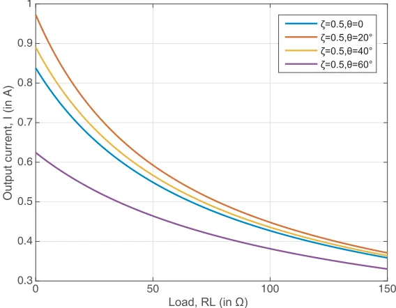
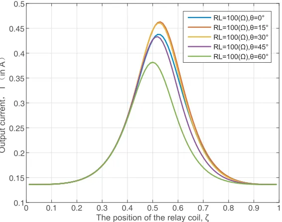
Figure 6. Relationship between output currentI3 and loadRL, when the coil positionζ = 0.5.
power decreases evidently. So the maximum value of output power can be obtained whenζ ∈[0.55,0.60]. In addition, the location of relay coilζ has influence on rotation anglesθopt for maximum output power. Figure 6 shows the relationship between output currentI3 and load RL when the relay coil is fixed in the middle of transmitting coil and receiving coil, and the rotation angleθ of relay coil is set to 0◦, 20◦, 40◦, and 60◦, respectively.
As can be seen from Figure 6, rotating relay coil is beneficial to increasing the output current I3
through the load, but the excessive rotation angle will decreaseI3. It shows that for the same load, the
output current I3 increases with the increase of rotation angle θ when θ ∈ [0◦, 20◦]. But the output
0 500 1000 1500 0
5 10 15 20 25
Output power, P (in W)
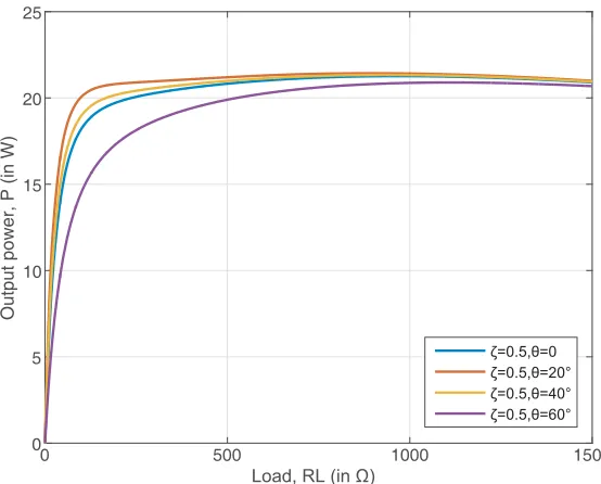
Figure 7. Relationship between output powerPout and loadRLwhen the location of relay coilζ = 0.5.
load, rotating relay coil can increase I3 andPout to some extent.
Figure 7 shows the relationship between output powerPout and loadRL when the relay coil is fixed in the middle of transmitting coil and receiving coil, and the rotation angle θ of relay coils are 0◦, 30◦, 45◦, and 60◦, respectively.
As can be seen from Figure 7, for each curve, there is always a load RL that makes the system get the maximum output power when relay coil position and rotation angle are fixed. For the same location and different rotation angles, the loadRL corresponding to the maximum output powerPout is
also different. When the rotation angle exceeds the optimal rotation angleθopt, the greater the rotation
angle θis, the greater the resistance of corresponding load RL will be.
Figure 8 shows the relationship between output current I3 and position of relay coil ζ when load RL is fixed to 100 Ω, and the rotation angles of relay coil θ are 0, 30◦, 45◦, and 60◦, respectively.
It can be seen from Figure 8 that the maximum output power Pout can be obtained when ζ is
slightly larger than 0.5. According to the model of WPT system, RS is usually not equal to RL. If RL > RS, the output power Pout can reach maximum whenζ is slightly greater than 0.5. If RL < RS,
the output powerPout can reach the maximum whenζ is slightly less than 0.5. In addition, for a certain
RL (RL > RS), if the rotation angle of relay coil θ satisfies θ∈ [0◦, θopt], to get the maximum output power Pout, the position of relay coil ζ is increased with the increase of angleθ. If the rotation angle of relay coil θ satisfiesθ∈[θopt,90◦], to get the maximum output powerPout, the position of relay coil ζ
is decreased with the increase of angle θ.
Figure 9 is the iteration result of output powerPout in genetic algorithm, considering the position
of relay coil ζ, rotation angle of relay coil θ, and load RL at the same time.
It can be seen from Figure 9, the maximum output powerPout can be obtained by genetic algorithm
in very few iterations. The maximum output power is obtained when the iteration number is about 70. It shows the algorithm advantage of fast convergence to optimize the multi-objective function. After calculation, the rotation angle of relay coil θ = 18.57◦, load RL = 928.5 Ω, and position of relay coil ζ = 0.619. According to formulas (13) and (14), the maximum output power Pout = 21.1045 W, and
the efficiency η= 58.62%.
5. EXPERIMENTAL VALIDATION
0 0.1 0.2 0.3 0.4 0.5 0.6 0.7 0.8 0.9 1 0.1
0.15 0.2 0.25 0.3 0.35 0.4 0.45 0.5
Figure 8. Relationship between the output current I3 and the location of the relay coil ζ when the loadRL= 100 Ω.
0 20 40 60 80 100 120 140 160 180 200
Iteration times
4 6 8 10 12 14 16 18 20 22
Output power, Pout (in W)
Figure 9. Relationship between the output powerPout and the iteration numbers.
frequency signal generating circuit, which provides high frequency AC signals to the high frequency power amplifying circuit. The second part is a high-frequency power amplifier. The DC power supply provides energy for power amplifier. The high-frequency AC signal flows through the amplifier circuit to provide high-frequency power to the transmitting coil. The third part is a coil coupling part, which transmits energy to the load through the conversion of electric field and magnetic field.
Figure 10. Schematic diagram of experimental device for MCRWPT system with relay coil.
Figure 11. Physical picture of experimental device for MCRWPT system with relay coil.
signal is amplified by a power amplifier. Under the condition of impedance matching, the overall gain of the power amplifier is about 40 dB, and the amplification factor is about 10000 times. The output of the power amplifier is about 36 W measured by a standing wave meter, which provides energy for the transmitting coil. In order to make the system resonant, the transmitting coil, relay coil, and receiving coil are connected in series with a ceramic air adjustable capacitor. In the conversion between electric field energy and magnetic field energy, the energy is transmitted to the load of the receiving coil.
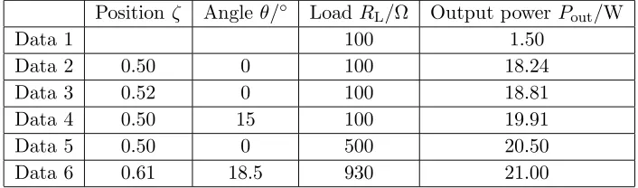
Table 1 shows the data obtained from the operation of experimental device. The distance between the transmitting coil and receiving coil is 0.21 m, and the load is 100 Ω. In the absence of relay coils, the output power is 1.5 W. The system output power is obviously insufficient, and the system is under-coupled. In order to improve the output power, the relay coil is introduced while keeping the position of transmitting coil and receiving coil unchanged. However, when the output power is increased, the frequency splitting occurs due to the excessive coupling between adjacent coils. The frequency splitting
Table 1. Experimental data of positionζ, rotation angleθ, load RL, and output powerPout.
Position ζ Angle θ/◦ LoadRL/Ω Output power Pout/W
Data 1 100 1.50
Data 2 0.50 0 100 18.24
Data 3 0.52 0 100 18.81
Data 4 0.50 15 100 19.91
Data 5 0.50 0 500 20.50
phenomenon can be suppressed by taking corresponding measures to further improve the output power. The specific data are shown in Table 1 below.
As shown in data 1, in the traditional two-coil MCRWPT system, when the load is 100 Ω, and the output power is only 1.5 W. When a relay coil is added in the middle of transmitting coil and receiving coil, as shown in data 2, the output power is increased from 1.5 W to 18.24 W. However, the system directly transits from the original under-coupled state to the over-coupled state. In order to suppress frequency splitting, the position of relay coil, rotation angle of relay coil, and load are adjusted, respectively. Compared with data 2, the system output power is further improved, as shown in data 3 to data 6. The experimental device tests and verifies the simulation result in some degree.
6. CONCLUSION
In the MCRWPT system with relay coil, because the positions of transmitting coil and receiving coil are fixed, the introduction of relay coil may make system charging state change from under-coupling state to over-coupling state, and at the same time frequency splitting phenomenon may appear in the system. By adjusting the rotation angle, position of relay coil, and load resistance, the frequency splitting is suppressed so as to further increase the output power. The simulation results show that when the rotation angle θ= 18.57◦, the load resistance RL= 928.5 Ω, the position ζ = 0.619, and the maximum
output power Pomax = 21.1045 W. Compared with the traditional structure that the relay coil is in
the middle, the output power changes from 18.24 W to 21.1045 W, increasing by about 15.7%. The transmission efficiency changes from 50.67% to 58.62%, increasing by about 8%. Finally, an MCRWPT system with relay coil is designed and verifies the simulation result in some degree.
ACKNOWLEDGMENT
This work was supported by the National Natural Science Foundation of China (No. 61501106), Science and Technology Foundation of Jilin Province (No. 20180101039JC), and Science and Technology Foundation of Jilin City (No. 201831775).
REFERENCES
1. Liu, Z., Z. Z. Chen, X. Q. Lin, and H. P. Zhao, “Review of research on magnetic coupling resonant wireless power transmission,”Journal of Nanjing University of Information Science and Technology (Natural Science Edition), Vol. 9, No. 1, 1–7, 2017.
2. Lipu, M. S. H., M. A. Hannan, A. Hussion, M. M. Hoque, P. J. Ker, M. H. M. Saad, and A. Ayob, “A review of state of health and remaining useful life estimation methods for lithium-ion battery in electric vehicles: Challenges and recommendations,” Journal of Cleaner Production, Vol. 205, No. 1, 115–133, 2018.
3. Panchal, C., S. Stegen, and J. Lu, “Review of static and dynamic wireless electric vehicle charging system,” Engineering Science and Technology, an International Journal, Vol. 21, No. 1, 922–937, 2018.
4. Kalwar, K. A., M. Aamir, and S. Mekhilef, “A design method for developing a high misalignment tolerant wireless charging system for electric vehicles,” Measurement, Vol. 118, No. 1, 237–245, 2018.
5. Hafez, O. and K. Bhattacharya, “Optimal design of electric vehicle charging stations considering various energy resources,”Renewable Energy, Vol. 107, No. 1, 576–589, 2018.
6. Joseph, P. K. and D. Elangovan, “A review on renewable energy powered wireless power transmission techniques for light electric vehicle charging applications,”Journal of Energy Storage, Vol. 16, No. 1, 145–155, 2018.
7. Ahn, D. and S. Hong, “A study on magnetic field repeater in wireless power transfer,” IEEE Transactions on Industrial Electronics, Vol. 60, No. 1, 360–371, 2013.
9. Ahn, D. and S. Hong, “A transmitter or a receiver consisting of two strongly coupled resonators for enhanced resonant coupling in wireless power transfer,” IEEE Transactions on Industrial Electronics, Vol. 61, No. 3, 1193–1203, 2014.
10. Lu, Z. J., X. T. Ma, W. C. Tang, Z. Y. Yu, and H. Y. Zhang, “High efficiency wireless energy transmission technology based on loading auxiliary coils,” Journal of North China Electric Power University (Natural Science Edition), Vol. 45, No. 1, 66–72, 2018.
11. Li, X. H., L. J. Gong, and Y. Li, “The influence of coil orientation on the performance of magnetically coupled resonant wireless power transmission system,” Science and Technology and Engineering, Vol. 17, No. 26, 62–68, 2017.
12. Wang, J. H., J. G. Li, S. L. Ho, W. N. Fu, Y. Li, H. L. Yu, and M. G. Sun, “Lateral and angular misalignments analysis of a new PCB circular spiral resonant wireless charger,”IEEE Transactions on Magnetics, Vol. 48, No. 11, 4522–4525, 2012.
13. Yin, J. B., Design Method of Coupled System Based on Asymmetric Structure and Research on Characteristics of Wireless Energy Transmission, Tianjin Polytechnic University Press, Tianjin, 2018.
14. Karaca, O., F. Kappeler, D. Waldau, R. N. Kennel, and J. Rackles, “Eigenmode analysis of a multiresonant wireless energy transfer system,” IEEE Transactions on Industrial Electronics, Vol. 61, No. 8, 4134–4141, 2014.
15. Lan, J. Y., H. J. Tang, and X. Gen, “Frequency splitting analysis of wireless power transfer system based on T-type transformer model,”Elektronika Ir Elektrotechnika, Vol. 19, No. 10, 109–113, 2013. 16. Zhang, Y. M. and Z. M. Zhao, “Frequency splitting analysis of two-coil resonant wireless power
transfer,”IEEE Antennas and Wireless Propagation Letters, Vol. 13, No. 1, 400–402, 2014. 17. Lyu, Y. L., F. Y. Meng, G. H. Yang, B. J. Che, Q. Wu, L. Sun, D. Erni, and J. L. W. Li, “A
method of using non-identical resonant coils for frequency splitting elimination in wireless power transfer,”IEEE Transactions on Power Electronics, Vol. 30, No. 11, 6097–6107, 2015.
18. Narayanamoorthi, R., J. Vimala, P. Sanjeevikumar, M. P. Lucian, and C. Bharatiraja, “Frequency splitting elimination and cross-coupling rejection of wireless power transfer to multiple dynamic receivers,”Applied Sciences, Vol. 8, No. 2, 179–197, 2018.
19. Li, Z. Q., S. D. Huang, J. L. Yi, and J. J. Li, “Suppression method of frequency splitting for magnetically coupled resonant wireless power transmission system,”Automation of Electric Power Systems, Vol. 41, No. 2, 21–27, 2017.
20. Huang, X. L., Q. J. Ji, L. L. Tan, W. Wang, J. M. Zhao, and Y. L. Zhou, “Study on series-parallel model of wireless power transfer via magnetic resonance coupling,”Transactions of China Electrotechnical Society, Vol. 28, No. 3, 171–187, 2013.
21. Tan, L. L., Research on Characteristic and Control Strategies for Magnetic Resonance Coupled Wireless Power System, Southeast University Press, Nanjing, 2014.