Energy-Efficient Coding Matrix FMD-RDA Secure Transmission
Scheme Based on Quadrature Spatial Modulation
for mmWave Systems
Shaddrack Y. Nusenu1, 2, * and Abdul Basit1, 3
Abstract—Artificial noise (AN) aided method in mmWave is hard to realize due to large transmit antennas and also requires additional power. This paper proposes coding matrix secure transmission based on quadrature spatial modulation (QSM) utilizing a frequency modulated diverse retrospective array (FMD-RDA). Specifically, we adopt coding matrix for frequency increment with QSM symbols to form part of FMD-RDA angular-range array factor. Consequently, low probability of detection (LPD) is created during the QSM transmission without additional power. The desired receiver should know the particular coding matrix a priori. Importantly, the system has automatic user tracking ability with no channel state information (CSI) needed at the desired receiver and can handle receivers with highly correlated channels. Further, secrecy outage probability (SOP), asymptotic lower bound on eavesdropper’s (Eve’s) detecting error probability and average data leakage rate are analyzed without Eve’s CSI. Simulation results show that increasing the coding matrix, satisfactory secrecy is attained for the proposed scheme. Moreover, through the results certain essential secrecy information has been highlighted that is not captured by the classical SOP making the proposed scheme an attractive technique for QSM applications.
1. INTRODUCTION
Millimeter wave (mmWave) system has been one of the attractive systems to meet the data capacity especially for fifth-generation (5G) wireless technology [1] and even beyond. The mmWave provides abundant bandwidth spectrum, rangeing from 30 GHz (with wavelength 10 mm) to 300 GHz (with wavelength 1 mm), which can be explored to significantly increase the data rate. Additionally, mmWave offers small wavelength that makes it possible for large antennas to be deployed in a small physical area [2–4]. In the literature, several authors have investigated smart antennas which are also feasible in mmWave communication applications [5–14].
In recent years, spatial modulation (SM) technique [15, 16] as an alternative multi-antenna scheme has attracted much attention. The SM scheme has many promising advantages and is primarily focused on communication applications to provide spectral efficiency, low complexity design, and reliability [17– 20]. Due to the massive connectivities of users in 5G mmWave technology as a result of the broadcast nature of wireless characteristics, it is important to tackle security issues.
Physical layer security (PLS) has been investigated [21, 22] which is proven to improve the wireless systems secrecy [23–25]. Several authors have investigated SM based PLS techniques [26–31]. Very recently, a new variant of SM, namely quadrature spatial modulation (QSM), was proposed [32] to alleviate the drawbacks of SM [15, 16].
Received 14 February 2019, Accepted 28 March 2019, Scheduled 11 April 2019 * Corresponding author: Shaddrack Y. Nusenu ([email protected]).
In [33], AN security method was developed for QSM scheme. Although AN methods offer security, in mmWave more transmit antennas can be deployed due to small wavelength, hence, AN implementation will be difficult to realize practically [34]. Secondly, AN causes the data transmission power to decrease leading to reduction of signal-to-interference-plus noise ratio at the desired receiver. Thirdly, in channels that are highly correlated, AN failed to provide better security [35]. Therefore, alternative security methods with low energy consumption have to be considered.
In recent years, retrodirective array (RDA) [36] which can offer self-tracking automatically and facilitate retransmission of signal along interrogator direction with no priori knowledge of the arrival of the incoming angle has been investigated in [37–39]. More importantly, utilizing RDA does not required CSI (i.e., bandwidth can be saved) at the receiver. Note that in most of the existing QSM systems require CSI at the receiver for retrieving the information bits [40–42].
In this paper, we propose secure transmission based on QSM utilizing FMD-RDA for mmWave systems. Explicitly, coding matrix is adopted to design the small frequency increment and embed the QSM bits as part of the FMD-RDA range-angle array factor. Consequently, we can create low probability of detection (LPD) during the QSM transmission without additional power. It is assumed that the desired receiver knows the coding matrix a priori, allowing detecting the transmitted QSM bits. Importantly, the proposed scheme has automatic user tracking ability with no CSI needed at the desired receiver and can handle receivers with highly correlated channels due to angular-range focusing profile. Further, secrecy outage probability (SOP), asymptotic lower bound on Eve’s detecting error probability, and average data leakage rate are analysed without Eve’s CSI. The proposed scheme reveals essential secrecy information that is not captured by the classical SOP and is more power efficient.
The rest of the paper is organized as follows. Section 2 presents the proposed scheme. In Section 3, performance metrics are devised to evaluate the proposed scheme. In Section 4, numerical results are presented, and finally, in Section 5, we draw conclusions.
2. PROPOSED CODING MATRIX FREQUENCY MODULATED DIVERSE RETRODIRECTIVE ARRAY SECURE TRANSMITTER
2.1. System Model
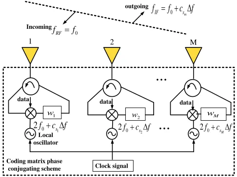
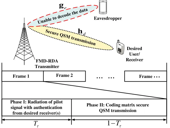
Consider a mmWave communication FMD-RDA transmitter system (see Fig. 1) where the desired transceiver wants to communicate, and a passive Eve tries to intercept the data (see the time frame block in Fig. 2). To establish secure transmission, we make the following assumptions:
outgoing
Spatial mapping
Clock signal Local
oscillator
data data
data
1
...
Incoming
0 RF
f = f
Coding matrix phase conjugating scheme
...
0 mIF s
f = + Δf c f
1 0
2f + Δcs f 2f0+ Δcs2 f 2f0+ ΔcsM f
1 w
2
w wM
2 M
(1) The pilot signal is emitted only by the desired receiver with authentication procedure. We omit how to tackle unwanted incoming pilot signals from Eve in this paper as future work.
(2) Multiple-input single-output (MISO) mmWave wireless communications have perfect synchroniza-tion between the proposed transmitter and desired receiver.
(3) To facilitate decoding, the desired receiver should know the coding matrix used for frequency increments designed a prior. Note that the coding matrix can be sent to the desired receiver via a low speed forward link [43].
(4) Eve’s activity is to intercept retransmission of the confidential useful data meant for the desired receiver during Phase II as depicted in Fig. 2.
Frame 1
Phase I: Radiation of pilot signal with authentication from desired receiver(s)
Desired User/ Receiver
... ...
Frame 2 Frame
Phase II: Coding matrix secure QSM transmission
T
τ1
−
T
τ...
FMD-RDA Transmitter
Eavesdropper
d
h
e
g
Figure 2. Time frame block is decomposed into two phases: The desired receiver emit pilot signal with authentication during Tr in phase I. After the pilot signal, the FMD-RDA transmitter re-transmit the confidential data during 1−Tr in phase II.
2.2. Coding Matrix Design for Secure Transmission
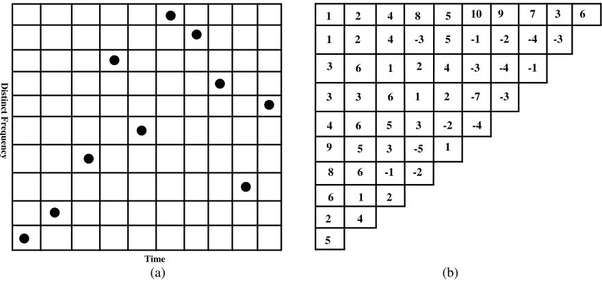
Without loss of generality, we assume coding matrix cs, i.e., M = 10, namely {1, 2, 4, 8, 5, 10, 9, 7, 3, 6} [44, 45] for our analysis, see Fig. 3(a) and Fig. 3(b), for the illustration of the coding matrix and difference matrix. More importantly the utilized order of frequencies (i.e., coding sequence) represents a concise fashion which describes the coding matrix. The difference matrix can be computed by Ψi,j = αi+j −αj with i+j ≤ M. Note that αi denotes the ith coding element, and i+j > M denote the remaining locations which are left blank. Note that the difference matrix shows that the coding matrix used is feasible. Considering the designed coding matrix, our proposed system allows for ten elements with frequency increments indexed as csMΔf with csM = {1,2,4,8,5,10,9,7,3,6}, and Δf denotes the frequency hopping step. It is important to note that without specified coding matrix of the frequency increments, it will be difficult to decipher the transmission process.
2.3. QSM Modulator Scheme
Following [32], herein, we demonstrate the principle of QSM transmission. We consider MISO and quadrature amplitude modulation (4-QAM). The bits to be reradiated at a certain time instant are represented byk = log2M0M2
= 6 bits. Suppose that k= [1 1 0 1 1 1]
log2(M0)+log2(M2)
Distinct Frequency
Time
1 2 4 8 5 10
1 2 4 -3 5
3 6 1 2
3 3 6
4 6
9
9 7 3 6
4 -3 -4 -1
-1 -2 -4 -3
1 2 -7 -3
5 3 -2 -4
5 3 -5 1
8 6 -1 -2
6 1 2
2 4
5
(a) (b)
Figure 3. Illustration of (a) Coding matrix cs,M = 10: {1,2,4,8,5,10,9,7,3,6} and (b) Difference matrix design.
desired receiver. The first log2(M0) bits [11] modulates the constellation symbol (4-QAM),x= +1−j. This symbol is decomposed into two, namely real part x = +1 and imaginary partx = −j. Next,
the log2(M) bits, [01], modulate the transmit element i.e.,= 2, to emit x = +1. The resultant is a
vector s= [0 + 1 0 0]T. Lastly, the log2(M) bits, [11], modulate another transmit element, = 4,
to radiate x = −j, resulting in the vector s = [0 0 0 −j]T. The resultant vector is obtained by adding the real and imaginary vectors. Hence, the signal vector to be transmitted is
s=s+s = [0 + 1 0 −j]T (1)
Vector s in Eq. (1) is reradiated to the desired receiver by FMD-RDA transmitter over an (M×1) mmWave channel hd. Note that the channel between the FMD-RDA transmitter and Eve isgd.
2.4. System Formulation
It should be noted that even if beamforming is not formed during retransmission, FMD-RDA is still able to phase conjugate the emitted pilot signal from the desired receiver. As illustrated in Fig. 2, in the first Tτ phase, pilot signal is emitted from the desired receiver (i.e., with authentication) to the FMD-RDA transmitter. Herein, we assume the principle of channel reciprocity. The pilot signal is represented as s(t) = exp (2πf0t). The incoming pilot signal is detected at the FMD-RDA transmitter
mth element as
ym(t) = exp
j2πf0
t−r−mdsinθin c
(2)
where the range approximation is rm ≈ r −mdsinθin, with r being range of the desired receiver and FMD-RDA transmitter first reference element. θin is originated from the desired receiver (i.e., pilot signal incoming angle). According to Fig. 1, the incoming pilot signal received by the FMD-RDA transmitter (i.e.,mth element) is mixed with phase-conjugate mixers (i.e., local oscillator (LO) signal), then we have
fLOm = 2f0+ Δfm(t) ; m= 1,2, . . . , M (3)
where Δfm(t) is formulated as
Δfm(t) =
Pt(hx+jhx)·csmΔf(t) (4)
constellation; h and h are the mmWave channel coefficient between the activated FMD-RDA
antennas and desired receiver. , = 1,2,· · ·M and Pt denotes the FMD-RDA transmitted power. In the second 1−Tτ phase (see Fig. 2), the retransmitted signal by the FMD-RDA transmitter arriving at a particular time t1 to the desired receiver is written as
y
t1;θd=θdin, rd
= expj2πf0
t−rd−r
c
M
m=1
wmexpj2πΔfm
t−rm c
·
t−rd−mdsinθd
c expj2πmd
sinθd−sinθind
λ
(5)
wherewm is the phase weighting, andλis the wavelength. Note that noise term is not considered. And
rm ≈r−mdsinθ has the same physical interpretation as in Eq. (2). It is important to note that the transmitted QSM symbols form part of the retransmit angle-range array factor as seen in Eq. (5).
Similarly, Eve retransmitted signal arriving at a certain timet2 is also given as
y(t2;θe=θine , re) = expj2πf0
t− re−r
c
M
m=1
wmexpj2πΔfm
t−rm c
·
t−re−mdsinθe
c expj2πmd
sinθe−sinθine
λ
(6)
It should be noted that from Eq. (6), we can deduce that even if Eve receives the retransmitted useful signal from FMD-RDA transmitter, it will still be difficult to decode it without the specified coding matrix used for designing the frequency increments.
Remark: The FMD-RDA transmitter frequency and incident frequency should be equal f = f0.
If f = f0, according to [46], their frequency differences can be linked directly. Hence, the FMD-RDA transmitter is still feasible to offer security capability.
2.5. Optimal Maximum Likelihood (ML) Detection
Note that since the desired receiver radiates pilot signal to the FMD-RDA transmitter, there is no need of CSI at the receiver. Therefore, using the optimal ML detector, we have
ˆ
,ˆ,xˆ,xˆ
= arg min ,,x,x
y
t1, θd=θdin, rd
−Pt(hx+jhx)·csmΔf
2
= arg min ,,x,x
Ψ2−2
yH
t1, θd=θdin, rd
Ψ
(7)
where Ψ =√Pt(hx+jhx)·csmΔf. In order to retrieve the original useful information bits, the receiver used the detected antenna ˆ and ˆalong with the detected data symbols, namely ˆxand ˆx. In addition, we assume that the receiver knows the coding matrixcsm used for the frequency increment a prior.
3. PERFORMANCE ANALYSIS
3.1. Secrecy Outage Probability (Ps)
The achievable rate from the FMD-RDA transmitter to the desired receiver is determined by
Cd(θd, rd, t) = log2(1 +γd(t)) (8) where received instantaneous signal-to-noise ratio (SNR) at time tis
γd(t) =σ−d2wHa
θd=θdin, rd, t+rd
c
2
(9)
with w denoting the transmitter weight vector, σ2
Likewise, the achievable rate from the FMD-RDA transmitter to Eve receiver is
Cd(θd, rd, t) = log2(1 +γd(t)) (10) where
γe(t) =σe−2wHa
θe =θein, re, t+re
c
2
(11)
Eq. (11) has the same physical meaning as Eq. (9). The exponential distributions of the desired receiver and Eve are given respectively as
fd(γd(t)) = 1 ¯
γd(t) exp
−γd(t) ¯
γd(t)
(12)
fe(γe(t)) = 1 ¯
γe(t) exp
−γe(t) ¯
γe(t)
(13)
For the sake of simplicity, we define the received average SNRs along the desired receiver and Eve, respectively as ¯γd(t) =Ptσ−d2 and ¯γe(t) =Ptσ−e2.
Now, we consider the wiretap encoding technique [47]. Two rates are chosen by the encoder for the QSM bits, namely, codewords rate Rb and confidential data rate Rs. The rate cost to offer anti-eavesdropping is determined by the rate positive difference Re
Δ
= Rb −Rs. Suppose that we construct k length wiretap code which generates 2kRb codewords xk(, ξ), with = 1,2, . . . ,2kRs and
ξ= 1,2, . . . ,2k(Rb−Rs). ξis selected randomly from1,2, . . . ,2k(Rb−Rs)for the message index, having uniform probability and transmit codewordxk(, ξ). In this paper, fixed transmission rate is considered. This implies that Rb and Rs will be fixed over t. The desired receiver can detect the data correctly if
Cd(θd, rd, t)> Rb. IfCe(θe, re, t)> Re then security is compromised.
Following [48], we analyze the secrecy outage probabilityPsas follows: The wiretap code maximum achievable fractional equivocation for the proposed scheme is
Φ = 1
, if Ce(θe, re, t)≤Rb−Rs
(Rb−Ce(θe, re, t))/Rs, if Rb−Rs < Ce(θe, re, t)< Rb 0, if Rb ≤Ce(θe, re, t)
(14)
Therefore, secrecy outage probability Ps is equivalently given by
Ps=P(Φ< ψ)
=P2Rb−1≤γe(t)
+P2Rb−Rs −1< γe(t)<2Rb−1
·P
Rb−Ce(θe, re, t)
Rs < ψ
2Rb−Rs−1< γe(t)<2Rb−1
= exp
−2Rb−ψRs−1
¯
γe(t)
(15)
with 0 < ψ ≤ 1 giving the distinct secrecy options of Ps. Note that if ψ = 1, then classical SOP is obtained [49] meaning perfect secrecy, but note that we cannot always achieve perfect secrecy.
3.2. Eve’s Detecting Error Probability Lower Bound Analysis
The proposed scheme average fractional equivocation is determined as ¯
Φ =E{Φ}
=
2Rb−Rs−1
0
fe(γe(t))dγe+
2Rb−1
2Rb−Rs−1
Rb−Ce(θe, re, t)
Rs fe
(γe(t))dγe
= 1−(RsIn (2))−1exp (¯γe(t))−1
Ei
− 2Rb
¯
γe(t) −Ei
−2Rb−Rs
¯
γe(t)
(16)
where the exponential integral is denoted asEi(κ) = κ
−∞exp (t)/t dt. Explicitly, Eq. (16) highlights the
3.3. Average Data Leakage Rate Analysis
As previously stated, we adopt fixed transmission rate, and therefore, we formulate the average data leakage rate as
ADL=
1−Φ¯Rs
=(In (2))−1exp (¯γe(t))−1
Ei
− 2Rb
¯
γe(t)
−Ei
−2Rb−Rs
¯
γe(t)
(17)
It is important to note that Eq. (17) reveals averagely how the QSM bits can be leaked to Eve during the transmission process.
4. NUMERICAL RESULTS
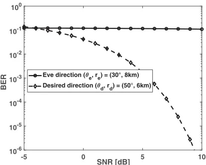
Suppose that the desired receiver is located at (50◦,6 km), andt1 = 0.02 ms indicates the reradiated wave arriving at the desired location. Eve is located at (30◦,8 km) with t2 = 0.0277 ms. The coding matrix forM = 4 and 6 are respectively given as {1,2,4,3} and {1,3,2,6,4,5}. f0= 30 GHz, Δf = 200 kHz, and Rb = 1 =Rs. For the next transmission, pilot signal frequency f0 needs to be estimated.
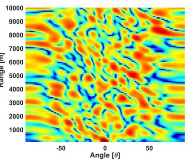
As already stated in Subsection 2.2, without the specified coding matrix of the frequency increments, it will be difficult to decipher the transmission process. In Fig. 4, we provide coding matrix FDM-RDA beamforming with M = 10. It can be seen from the figure that the beamforming shows random-like distributions without obvious peak. This means that it will be difficult for any unfriendly receiver(s) to detect the peak without the specified coding matrix adopted for the frequency increment. Analogous to this scenario, it is expected that using the coding matrix, it will be difficult for the eavesdropper(s) to decipher it.
Figure 4. Coding matrix FDM-RDA beamforming withM = 10 at desired receiver location (50◦,6 km).
Figure 5 plots SOP as a function ofRs. It can be noticed that for distinct values of ψ and coding matrixM, we achieve different secrecy performances. It should be mentioned that we can obtain perfect secrecy whenψ= 1. Also, it is observed that as SOP increases so does the confidential data rate. This implies that as M increases,the level of system secrecy becomes better.
As depicted in Fig. 6, we plot the average fractional equivocation ¯Φ as a function of ¯γe(t) for different values of coding matrixM. From the figure, we notice that ¯Φ decreases as ¯γe(t) increases. In essence, Eve may detect useful data when M ≤6.
In Fig. 7, we show the average data leakage rateADL against ¯γe(t) for different values of coding matrix M. We find that ADL increases as ¯γe(t) increases. This means that the useful data can be leaked to Eve’s location with M ≤6.
Eve detectability (i.e., worst scenario), and (c) how likely the useful data can be leaked to Eve. Note that these pieces of information are not captured when using the classical SOP [48].
Finally, Fig. 8 compares the security performance using bit error rate (BER). It can be seen that Eve performs worse (i.e., with no coding matrix a priori) than the desired receiver (i.e., with coding matrix a priori). This implies that the proposed scheme has offered good security transmission.
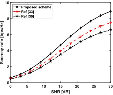
As shown in Fig. 9, the proposed scheme in MISO setup has better secrecy performance than [30] and [33]. Their secrecy rate values are around 9 bps/Hz, 6.4 bps/Hz and 7.4 bps/Hz, at 30 dB, respectively. In Table 1, we summarize the results of the proposed scheme [30] and [33].
0 0.2 0.4 0.6 0.8 1 1.2
Rs
0.1 0.2 0.3 0.4 0.5 0.6
Secrecy outage probablity, P
s
= 0.4, M = 6 = 0.6, M = 10 = 0.2, M = 4
Figure 5. SOP as function of Rs for distinct values ofψ and coding matrixM.
0 0.5 1 1.5 2
0.1 0.2 0.3 0.4 0.5 0.6 0.7 0.8
M = 10; 6;
Figure 6. Illustration of ¯Φ as a function of ¯γe(t) for distinct values of coding matrixM.
0 0.5 1 1.5 2 2.5
0 0.2 0.4 0.6 0.8 1 1.2
AD
L
M = 10; 6
Figure 7. Illustration of ADL against ¯γe(t) for distinct values of coding matrix M.
-5 0 5 10
SNR [dB]
10-6 10-5 10-4 10-3 10-2 10-1 100
BER
Eve direction ( e, re) = (30°, 8km) Desired direction (d, rd) = (50°, 6km)
Figure 8. BER comparisons between desired receiver (i.e., at t1 = 0.02 ms) and Eve receiver (i.e., att2= 0.0277 ms).
Table 1. Summary of results.
Parameters Propose scheme Ref. [30] Ref. [33] Secrecy rate 9 bps/Hz 6.4 bps/Hz 7.4 bps/Hz Transmit focusing Range-angle Only angle Only angle
0 5 10 15 20 25 30 SNR [dB]
0 2 4 6 8 10
Secrecy rate [bps/Hz]
Proposed scheme Ref [33] Ref [30]
Figure 9. Secrecy rate vs SNR comparisons.
5. CONCLUSION
In this paper, we have proposed an energy efficient security scheme using coding matrix FMD-RDA for QSM transmission in mmWave system. The proposed scheme provides LPD, thus, it is difficult to decipher the coding matrix used. On the other hand, the proposed scheme reveals important secrecy insights which are not captured by classical SOP, namely, different secrecy performance options, Eve’s detecting capability, and how fast the useful data are leaked towards Eve location. Our future work will be how to tackle unwanted incoming pilot signals from illegal interrogator (Eve) with new transmission techniques.
REFERENCES
1. Xiao, M., S. Mumtaz, Y. Huang, et al., “Millimeter wave communications for future mobile networks,” IEEE Journal on Selected Areas in Communications, Vol. 35, No. 9, 1909–1935, Sep. 2017.
2. Niu, Y., Y. Li, D. Jin, et al., “A survey of millimeter wave communications (mmwave) for 5G: opportunities and challenges,“ Wireless Networks, Vol. 21, No. 8, 2657–2676, Apr. 2015.
3. Andrews, J. G., T. Bai, M. N. Kulkarni, et al., “Modeling and analyzing millimeter wave cellular systems,”IEEE Transactions on Communications, Vol. 65, No. 1, 403–430, Jan. 2017.
4. Zhang, J. A., X. J. Huang, V. Dyadyuk, and Y. J. Guo, “Massive hybrid antenna array for millimeter wave cellular communications,” IEEE Wireless Communications, Vol. 22, No. 1, 79– 87, Feb. 2015.
5. Mohammad, A., B. S. Virdee, A. Ali, E. Limiti, “Extended aperture miniature antenna based on CRLH metamaterials for wireless communication systems operating over UHF to C-band,”Radio
Science, Vol. 53, No. 2, 154–165, Feb. 2018.
6. Mohammad, A., B. S. Virdee, P. Shukla, et al., “Interaction between closely packed array antenna elements using meta-surface for applications such as mimo systems and synthetic aperture radars,”
Radio Science, Vol. 53, No. 11, 1368–1381, Nov. 2018.
7. Mohammad, A., B. S. Virdee, C. H. See, et al., “Study on isolation improvement between closely-packed patch antenna arrays based on fractal metamaterial electromagnetic bandgap structures,”
IET Microwaves, Antennas and Propagation, Vol. 12, No. 14, 2241–2247, 28 Nov. 2018.
8. Mohammad, A., B. S. Virdee, P. Shukla, et al., “Meta-surface wall suppression of mutual coupling between microstrip patch antenna arrays for thz-band applications,” Progress In Electromagnetics
Research Letters, Vol. 75, 105–111, 2018.
applications,” International Journal of Electronics and Communications, Vol. 70, No. 12, 1645– 1650, Dec. 2016.
10. Mohammad, A., M. N.-M. Mohammad, R. A. Sadeghzadeh, et al., “New CRLH-based planar slotted antennas with Helical inductors for wireless communication systems, RF-circuits and microwave devices at UHF-SHF bands,”Wireless Personal Communications, Vol. 92, No. 3, 1029– 1038, Feb. 2017.
11. Mohammad, A., E. Limiti, M. N.-M. Mohammad, et. al., “A new wideband planar antenna with band-notch functionality at GPS, bluetooth and WiFi bands for integration in portable wireless systems,”International Journal of Electronics and Communications, Vol. 72, 79–85, Feb. 2017. 12. Mohammad, A., B. S. Virdee, A. Ali, and E. Limiti, “Miniaturized planar-patch antenna based on
metamaterial L-shaped unit-cells for broadband portable microwave devices and multiband wireless communication systems,”IET Microwaves, Antennas and Propagation, Vol. 12, No. 7, 1080–1086, 13 Jun. 2018.
13. Massimo, M. D., M. Toshifumi, and M. M. Hanifbhai, “A compact switched-beam planar antenna array for wireless sensors operating at Wi-Fi band,” Progress In Electromagnetics Research C, Vol. 83, 137–145, 2018.
14. Donelli, M. and P. Febvre, “An inexpensive reconfigurable planar array for Wi-Fi applications,”
Progress In Electromagnetics Research C, Vol. 28, 71–81, 2012.
15. Mesleh, R. Y., H. Haas, S. Sinanovic, et al., “Spatial modulation,” IEEE Transactions Veh.
Technol., Vol. 57, No. 4, 2228–2241, Jul. 2008.
16. Di Renzo, M., H. Haas, A. Ghrayeb, et al., “Spatial modulation for generalized MIMO: Challenges, opportunities, and implementation,”Proc. IEEE, Vol. 102, No. 1, 56–103, Jan. 2014.
17. He, L., J. Wang, C. Zhang, and J. Song, “Improving the performance of spatial modulation by phase-only pre-scaling,”Proc. IEEE Int. Conf. Communications (ICC), 3210–3215, London, U.K., Jun. 2015.
18. Li, X. and L. Wang, “High rate space-time block coded spatial modulation with cyclic structure,”
IEEE Communications Lett., Vol. 18, No. 4, 532–535, Apr. 2014.
19. Stavridis, A., S. Sinanovic, M. D. Renzo, and H. Haas, “Transmit precoding for receive spatial modulation using imperfect channel knowledge,” Proc. IEEE 75th Veh. Technol. Conf. (VTC
Spring), 1–5, Yokohama, Japan, May 2012.
20. Nusenu, S. Y. and W. Q. Wang, “Range-dependent spatial modulation using frequency diverse array for OFDM wireless communications,” IEEE Trans. Veh. Technol., Vol. 67, No. 11, 10886– 10895, 2018.
21. Hong, Y.-W. P., P.-C. Lan, and C.-C. J. Kuo, “Enhancing physical layer secrecy in multiantenna wireless systems: An overview of signal processing approaches,”IEEE Signal Process. Mag., Vol. 30, No. 5, 29–40, Aug. 2013.
22. Zou, Y. and J. Zhu,Physical Layer Security for Cooperative Relay Networks, Springer, New Year, NY, USA, 2016.
23. Trappe, W., “The challenges facing physical layer security,” IEEE Commun. Mag., Vol. 53, No. 6, 16–20, Jun. 2015.
24. Xiong, Q., Y. Gong, and Y.-C. Liang, “Achieving secrecy capacity of MISO fading wiretap channels with artificial noise,”Proc. IEEE Wireless Commun. Netw. Conf. (WCNC), 1–5, Shanghai, China, Apr. 2013.
25. Sun, L., P. Ren, Q. Du, et al., “Security-aware relaying scheme for cooperative networks with untrusted relay nodes,”IEEE Commun. Lett., Vol. 19, No. 3, 463–466, Mar. 2015.
26. Guan, X., Y. Cai, and W. Yang, “On the mutual information and precoding for spatial modulation with finite alphabet,”IEEE Wireless Commun. Lett., Vol. 2, No. 4, 383–386, Aug. 2013.
27. Yang, L.-L., “Transmitter preprocessing aided spatial modulation for input multiple-output systems,” Proc. IEEE Veh. Technol. Conf. (VTC-Spring), 1–5, Budapest, Hungary, May 2011.
secrecy communications,” IEEE Trans. Veh. Technol., Vol. 65, No. 1, 467–471, Jan. 2016.
29. Wu, F., L. L. Yang, W. Wang, and Z. Kong, “Secret precoding-aided spatial modulation,” IEEE
Commun. Lett., Vol. 19, No. 9, 1544–1547, Sep. 2015.
30. Wang, L., S. Bashar, Y. Wei, and R. Li, “Secrecy enhancement analysis against unknown eavesdropping in spatial modulation,” IEEE Commun. Lett., Vol. 19, No. 8, 1351–1354, Aug. 2015.
31. Chen, Y., L. Wang, Z. Zhao, et al., “Secure multiuser MIMO downlink transmission via precoding-aided spatial modulation,”IEEE Commun. Lett., Vol. 20, No. 6, 1116–1119, Jun. 2016.
32. Mesleh, R., S. S. Ikki, and H. M. Aggoune, “Quadrature spatial modulation,” IEEE Trans. Veh.
Technol., Vol. 64, No. 6, 2738–2742, Jun. 2015
33. Huang, Z., Z. Gao, and L. Sun, “Anti-eavesdropping scheme based on quadrature spatial modulation,” IEEE Commun. Lett., Vol. 21, No. 3, 532–535, Mar. 2017.
34. Ju, Y., H.-M. Wang, T.-X. Zheng, and Q. Yin, “Secure transmissions in millimeter wave systems,”
IEEE Transactions on Communications, Vol. 65, No. 5, 2114–2127, May 2017.
35. Lin, J., Q. Li , J. Yang, et al., “Physical-layer security for proximal legitimate user and eavesdropper: A frequency diverse array beamforming approach,” IEEE Transactions on
Information Forensics And Security, Vol. 13, No. 3, 671–684, Mar. 2018.
36. Fusco, V. and N. Buchanan, “Developments in retrodirective array technology,” IET Microw.,
Antennas Propag., Vol. 7, No. 2, 131–140, May 2013.
37. Ding, Y., V. F. Fusco, “A synthesis-free directional modulation transmitter using retrodirective array,”IEEE Journal of Selected Topics in Signal Processing, Vol. 11, No. 2, 428–441, Mar. 2017. 38. Yao, A.-M., W. Wu, and D.-G. Fang, “Frequency diverse array phase conjugating retrodirective array with simultaneous range-focusing capability for multi-targets,”Proceedings of the Asia-Pacific
Microwave Conference, Nanjing, China, 1–3, Dec. 2015.
39. Wang, W. Q., “Retrodirective frequency diverse array focusing for wireless information and power transfer,”IEEE Journal on Selected Areas in Communications, Vol. 37, No. 1, 61–73, 2019. 40. Mesleh, R. and S. Ikki, “On the impact of imperfect channel knowledge on the performance of
quadrature spatial modulation,”Proc. IEEE Wireless Communications and Networking Conference
(WCNC), 534–538, Mar. 2015.
41. Younis, A., R. Mesleh, and H. Haas, “Quadrature spatial modulation performance over Nakagami-m fading channels,”IEEE Trans. on Veh. Tech., Vol. 65, No. 12, 10227–10231, Dec. 2016.
42. Afana, A., R. Mesleh, S. Ikki, and I. Atawi, “Performance of quadrature spatial modulation in amplify-and-forward cooperative relaying,” IEEE Commun. Lett., Vol. 20, No. 2, 240–243, Feb. 2016.
43. Shu, F., Z. Wang, R. Chen, et al., “Two high-performance schemes of transmit antenna selection for secure spatial modulation,”IEEE Transactions on Vehicular Technology, Vol. 67, No. 9, 8969–8973, Sep. 2018.
44. Golomb, S. W. and H. Taylor, “Constructions and properties of Costas arrays,”Proceedings of the IEEE, Vol. 72, No. 9, 1143–1163, Sep. 1984.
45. Levanon, N. and E. Mozeson, Radar Signals, John Wiley and Sons, Inc., Hoboken, New Jersey, 2004.
46. Buchanan, N. B., V. F. Fusco, and M. Van Der Vorst, “Phase conjugating circuit with frequency offset beam pointing error correction facility for precision retrodirective antenna applications,”
Proceedings of the 41st European Microwave Conference, 1281–1283, Manchester, UK, Oct. 2011.
47. Wyner, A. D., “The wire-tap channel,” Bell Syst. Tech. J., Vol. 54, No. 8, 1355–1387, Oct. 1975. 48. He, B., X. Zhou and A. Lee Swindlehurst, “On secrecy metrics for physical layer security over
quasi-static fading channels,” IEEE Transactions On Wireless Communications, Vol. 15, No. 10, 6913–6924 Oct. 2016.