Low RCS Multi-Bit Coding Metasurface Modeling and Optimization:
MoM-GEC Method in Conjunction with Genetic Algorithm
Imen Soltani*, Takoua Soltani, and Taoufik Aguili
Abstract—We propose a new approach to design multi-bit coding metasurfaces (MSs) for broadband terahertz scattering reduction. An anisotropic graphene-based element with multiple reflection phase responses is modeled using the Method of Moments combined with the Generalized Equivalent Circuit’s approach (MoM-GEC). The multi-level reflection phase response is adjusted by tuning the graphene chemical potential of each cell. Based on the coding metamaterials concept, 1-bit MS building blocks are nominated as “0” and “1” elements with opposite phase responses 0◦ and 180◦, respectively. Therefore, the genetic algorithm (GA) is employed to search the optimal reflection phase matrix and determine the best coding metasurface layout. In order to validate our design strategy, 4×4, 8×8, 16×16, 32×32, and 64×64 arrays (MS) are modeled and show a great agreement with the desired low Radar Cross Section (RCS). In addition, 2-bit and 3-bit coding metasurfaces are then designed using two different sets of reflection phases {0◦,60◦,120◦,180◦}and {0◦,30◦,60◦,90◦,120◦,150◦,180◦,210◦}, respectively.
1. INTRODUCTION
Metasurfaces (MSs) consist of thin periodic and non-periodic sub-wavelength structures. This new class of artificial surfaces has attracted much attention due to its significant capability of manipulating electromagnetic waves. Numerous extraordinary functionalities have been introduced, such as the generalized law of reflection and refraction [1], perfect absorption [2], reflection/transmission phase modeling [3], polarization conversion [4], and holography [5]. Two major categories of metasurfaces were defined: static and dynamic. In the last few years, several researches and studies have focused on the development of dynamic programmable metasurfaces. In view of smart metasurfaces progress, dynamic coding metasurfaces [6] were proposed. Coding MSs is composed of N-types of units arrayed according to well-defined binary codes. Radar Cross Section reducing is one of the most favourable applications of coding metasurfaces. As a means to achieve this scattering field manipulation, the electromagnetic characterization of MS is a critical experience.
Hence, the design of metasurfaces has been studied massively based on the equivalent circuit model, effective impedance mode, FEM and FDTD methods [7–9]. However, in the case of coding metasurfaces, the design process becomes very challenging because their performance depends on many parameters such as physical propriety, geometry, the radiation pattern of each element, and the number of unit cells. In this context, the design of such metasurfaces [10, 11] should be considered as an optimization problem where the resolution tends to optimize the metasurface parameters in a desired manner. As reported in [12], beam rotation, resonance frequency shift, and radiation pattern reconfiguration of a monopole antenna have been studied and demonstrated using controllable metasurface. In fact, ¨Unnal and Altıntarla have used 1-bit coding metasurface based on digitally controlling the ON/OFF states using genetic algorithms. In this paper, based on graphene tunability, multi-bit coding metasurfaces are designed where the EM manipulation quality is improved by increasing the coding quantified levels.
Received 30 May 2018, Accepted 10 August 2019, Scheduled 26 August 2019 * Corresponding author: Imen Soltani ([email protected]).
2. THE MOM-GEC METHOD
The method of moments presents the most sufficient and global method to study discontinuities and to reduce the problem of dimensions by writing its boundary conditions in the form of integral equations. However, the process of solving this type of integral equations is expensive in terms of memory and time consumption. As long as the computational sophistication deeply depends on the studied structure geometry and parameters. The introduction of the Generalized Equivalent Circuit’s method (GEC) [13] presents the ultimate enhanced methodology to develop a simple integral equation formulation. The GEC method was proposed for the purpose of translating the electromagnetic resolution procedure (E, H) from the integral equations domain to the equivalent circuit’s one (V, I). Thus, a systematic derivation process of integral equations based on the introduction of operators — connected to Green’s operators with one fundamental function — instead of conventional impedance and admittance parameters is presented. Consequently, an electric image of the studied structure is created based on the discontinuity model. Accordingly, the EM discontinuity states are accurately described by trail functions. Therefore, the magnetic field (H) is substituted by the current density Je defined as Je = H ∧n, where n is the normal vector to the discontinuity plane. In addition, the modeling with GEC needs the presence of impedance or admittance operators, excitation sources, virtual sources, and an adequate waveguide walls choice for illustrating the physical problem.
2.1. Impedance and Admittance Operators
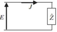
In the discontinuity plane, the boundary conditions are presented by a surface impedance ˆZ (or admittance ˆY) operator as depicted in Figure 1. Using these operators, we can deduce the relation between the field and current on the surface by a simple equation.
Figure 1. Representation of the impedance operator.
2.2. Excitation Source
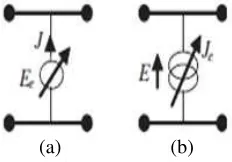
The located and modal sources are used to represent the excitation source at the discontinuity surface. This excitation source is called real source which delivers energy and can be either current or field source. The representation of real field and current sources is illustrated in Figure 2.
2.3. Virtual Source
The electromagnetic state of the discontinuity is described by generalized trial (test) functions. Those test functions are integrated in an equivalent circuit by a virtual source which does not deliver energy. The representation by virtual sources permits the expression of all passage relations imposed on electromagnetic field when traversing a discontinuity. Two types of test functions are used, where the current test function defines the graphene patterns, and the field test function represents the dielectric ones. These two representations are shown in Figure 3.
(a) (b)
Figure 2. Symbolic notation of excitation sources: (a) Field excitation source; (b) Current excitation source.
(a) (b)
Figure 3. Symbolic notation of virtual sources: (a) Field source; (b) Current source.
number of sinusoidal and triangular test functions are used to get the solution. In this paper, we will use the sinusoidal test function.
3. APPLICATION OF MOM-GEC METHOD ON THE METASURFACE UNIT CELL
A MoM-GEC-based MATLAB code is used to perform the electromagnetic analysis of the MS’ unit cell. As illustrated in Figure 4(a), the unit cell is immersed in a rectangular (EEEE) electric waveguide with ‘a’ and ‘b’ dimensions in x-y axis, respectively. Indeed, the front part of the waveguide is infinite (open-circuited) outlined in detail by an impedance operator ˆZM as depicted in Equation (1). Besides, the back part is short-circuited described by an admittance operator ˆYsub as shown in Equation (2). The two operators are written based on the modal basis of the waveguide, which are expressed by the waveguide modes fm,n [14, 15] and the total modal admittance and impedance for T Em,n and T Mm,n
modes: z((mn,T opT E,T M)) andy((mn,BottomT E,T M) ).
ˆ
ZM = fm,n > z((mn,T opT E,T M))< fm,n (1)
ˆ
Ysub = fm,n > y((mn,BottomT E,T M) ) < fm,n (2)
The graphene ribbon is characterized by a surface impedance operatorZs. In fact,Zs is calculated using the graphene sheet surface impedance per unit length as highlighted in Equation (3), which can be defined as the sum of resistance Rs and reactance Xs.
Zs= 1
σ(ω) =Rs+jXs (3)
(b) (a)
where Ef = chemical potential (ev), ω = Angular frequency, T = Temperature in units of K, KB = Boltzmann constant, = Planck’s constant, e= Electron volt,τ−1 = relaxation frequency.
The unit cell is excited by a TEM sourceEin as illustrated in Figure 4(b). The resolution of this electromagnetic problem tends to calculate the current density Je occurring on the graphene part. Je
can be expressed as:
Je(x, y) = Ny
i=1
xigi(x, y) (5)
whereNy is the number of trail (test) functions gi.
Using the Kirchoff’s and Ohm’s laws applied to the equivalent circuit of Figure 4(b) leads to the following equation system:
⎧ ⎪ ⎨ ⎪ ⎩
Je=J1+J2=J0 (6a)
Ein−ZˆMJ1+ ˆZsJe−Ee= 0 (6b)
Ee−ZˆsJe = ˆYsubJ2 (6c)
The equation system (6) can be written in matrix form connecting the real sourceEin(=V0f0) and
virtual sourceEeto these dual quantities. CurrentJ0 is defined as mode functions combination of basis
functionfm,n: J0 =I0f0. J0 Ee =
0 ( ˆYsubYˆM + 1)
−( ˆYsubYˆM + 1) Yˆsub+ ˆYM+ ˆZs Ein
Je
(7)
By applying the Galerkin method, the EM problem is described by a matrix equation combining matrix ‘B’ of boundary conditions, matrix ‘A’ of the excitation term, and the unknown vector ‘X’ composed of xi coefficient of current density Je. In this sense, the matrix system in Eq. (7) will be
conveyed as: I0 [0] = 0 A
−AT B V0
[X]
(8)
where
B[i, j] = < gi|ZˆMgj >+< gi|Zˆsgj >+< gi|Yˆsubgj > (9a)
A[i] = V0< gi|f0 >+V0 < gi|YˆMYˆsubf0 > (9b)
Now, the input impedance and the reflection coefficient can be deduced as depicted in Equations (10) and (11), respectively.
Zin = (AB−1At)−1 (10)
S11 =
Zin−ZT EM
Zin+ZT EM (11)
whereZT EM = 377 Ω.
(a) (b)
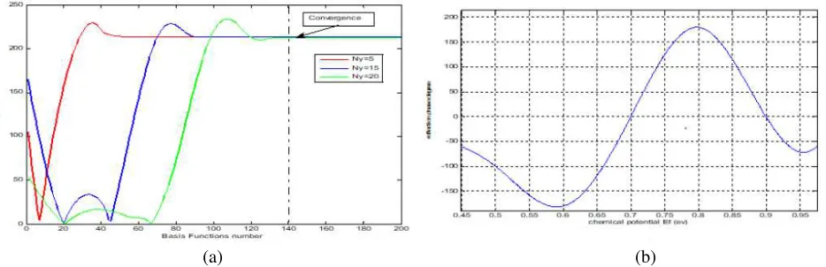
Figure 5. (a) MoM-GEC convergence and stability study. (b) Reflection phase evolution as a function of graphene chemical potential Ef.
4. METASURFACE DESIGN USING GENETIC ALGORITHMS
According to the coding metasurface design, a metasurface composed ofM×N graphene based elements of varied reflection phases is proposed. Primarily, two coding elements owing to two opposite reflection phases “0◦” and “180◦” are generated by varying the chemical potential of the graphene ribbon Ef, forEf = 0.7 ev and Ef = 0.8 ev, respectively. The reflection amplitude of each unit cell is normalized to 0.99 due to the gold film grounded in the back. Based on the antenna array theory [17], the total scattering field of the array can be expressed as:
T SFm,n(θ, ϕ, ϕr) = M m=1 N n=1
AFm,n(θ, ϕ, ϕr)∗EP (12)
ϕ,θare the azimuthal and polar angles, respectively. ϕr(m, n) is the reflection phase at each unit cell. EP represents the radiation pattern of each unit cell, is equal to 1 (isotropic), and will be neglected in our design. AFm,n(θ, ϕ, ϕr) is the array factor expression as highlighted in Equation (13), wheredx and
dy are the distance between two adjacent elements along the x andy directions, respectively.
AFm,n(θ, ϕ, ϕr) = M m=1 N n=1
exp(iϕr(m, n)) exp
i2π λ
dx
m−1
2
sinθsinϕ+vdy
n−1
2
sinθsinϕ
(13) To achieve the goal of reducing RCS, a real number encoding genetic algorithm is adopted to implement the optimal layout determination. The genetic algorithm is a global optimization algorithm that simulates the natural selection process. So, the GA approach is populated by selection, crossover and mutation operators. In fact, an initial population enters the main GA loop to search for the optimum solution of the defined problem. This loop is controlled by the fitness function and termination conditions. Thus, the GA is an effective global optimizer suitable for binary coding electromagnetic problems.
In this article, the genetic algorithm operates directly on a gene of the binary coding sequence of reflection phase matrix. Every gene is transformed to an individual using Equation (13). A number of individuals form a generation. At every generation, the corresponding scattering performances are evaluated by minimizing the cost function illustrated in Equation (14).
Cost = max(T SFm,n) (14)
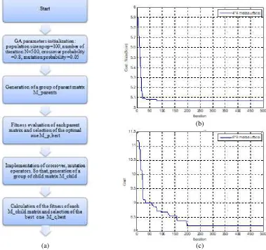
Figure 6 shows the flowchart of the proposed layout optimization method and the evolution plot of the cost functions minimization: max(T SF4,4) and max(T SF8,8). As a result, the maximum value of the
(a)
(b)
(c)
Figure 6. (a) GA flow chart. (b)–(c) The evolution plot of cost function reduction of max(T SF4,4),
max(T SF8,8).
5. RESULTS AND DISCUSSION
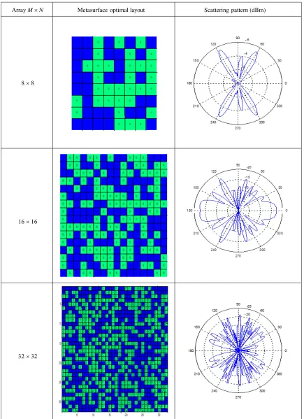
In this section, metasurfaces of 8×8, 16×16, 32×32, and 64×64 arrays under normal incidence have been designed and optimized using our modeling strategy. By comparing the array sizes, we are able to demonstrate that the RCS reduction increases when the unit cells number N×M is extended. 8×8, 16×16 and 32×32 optimal coding phase distributions and their corresponding 2-DE-plane scattering fields are shown in Table 1.
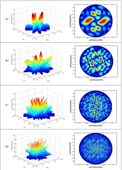
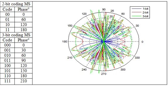
Furthermore, the 2-D and 3-D scattering patterns of each optimized layout are depicted in Table 2. It can be clearly seen that the number of array elements directly affects the broadband scattering reduction. Thereby, with the growing amount of N ×M, the electric field scattering pattern of the optimized phase distributions shows that the diffusions are perfectly achieved. The diffusion effects of Terahertz waves are performed to 64×64 coding metasurfaces with 1-bit, 2-bit, and 3-bit coding sequences. It is clear that the energy is redistributed to multiple directions as illustrated in Figure 7.
Table 1. Summarizing table of 2D scattering field of each optimal metasurface.
Array M × N Metasurface optimal layout Scattering pattern (dBm)
8 × 8
16 × 16
(a)
(b)
(c)
Figure 7. 2-D E-plane scattering fields of 64×64 coding metasurfaces with 1-bit, 2-bit and 3-bit coding sequences.
6. CONCLUSION
A multi-bit low RCS coding metasurface has been proposed. An isotropic graphene-based unit cell is modeled using the method of moments combined with the generalized equivalent circuit approach. In addition, to avoid strong energy appearing, the genetic algorithm is adopted to search the optimal reflection phase matrix and the layout of multiple elements metasurfaces. The results of optimal metasurfaces are in good agreement with the desired field diffusion characteristics. The 64 ×64 metasurface with 3-bit coding sequence presents the optimal desired performance.
REFERENCES
1. Achouri, K. and C. Caloz, “Space-wave routing via surface waves using a metasurface system,”Sci. Rep., Vol. 8, No. 1, 1–9, 2018.
2. Zhu, W., F. Xiao, M. Kang, and M. Premaratne, “Coherent perfect absorption in an all-dielectric metasurface,”Appl. Phys. Lett., Vol. 108, No. 12, 1–5, 2016.
3. Wu, K., P. Coquet, Q. J. Wang, and P. Genevet, “Modelling of free-form conformal metasurfaces,” Nat. Commun., Vol. 9, No. 1, 1–8, 2018.
4. Akgol, O., E. ¨Unal, O. Altintas, M. Karaaslan, F. Karadag, and C. Sabah, “Design of metasurface polarization converter from linearly polarized signal to circularly polarized signal,”Optik, Vol. 161, No. 10 1968, 12–19, 2018.
5. Deng, Z.-L. and G. Li, “Metasurface optical holography,”Mater. Today Phys., Vol. 3, No. 5 9 2011, 16–32, 2017.
6. Jafar-Zanjani, S., S. Inampudi, and H. Mosallaei, “Adaptive genetic algorithm for optical metasurfaces design,” Sci. Rep., Vol. 8, No. 1, 1–16, 2018.
7. Nye, N. S., A. Swisher, C. Bungay, et al., “Design of broadband anti-reflective metasurfaces based on an effective medium approach,” Proc. SPIE 10181, Advanced Optics for Defense Applications: UV through LWIR II, 101810J, Anaheim, California, United States, 2017.
8. Pulido-Mancera, L., P. T. Bowen, M. F. Imani, et al., “Polarizability extraction of complementary metamaterial elements in waveguides for aperture modeling,” Phys. Rev. B, Vol. 96, No. 235402, 1–14, 2017.
9. Wu, K., P. Coquet, Q. J. Wang, et al., “Modelling of free-form conformal metasurfaces,” Nat. Commun., Vol. 9, No. 3494, 1–8, 2018.
2019.
13. Baudrand, H. and D. Bajon, “Equivalent circuit representation for integral formulations of electromagnetic problems,”Int. J. Numer Model Electron Networks, Devices Fields, Vol. 15, No. 1, 23–57, 2002.
14. Hajji, M., M. Aidi, H. Krraoui, and T. Aguili, “Hybridization of generalized Po and Mom-Gec method for electromagnetic study of complex structures: Application to reflectarrays,”Progress In Electromagnetics Research M, Vol. 45, 35–49, 2016.
15. Aidi, M., M. Hajji, B. Hamdi, and T. Aguili, “Graphene nanoribbon modeling based on MoM-GEC method for antenna applications in the terahertz range,”2015 World Symposium on Mechatronics Engineering and Applied Physics (WSMEAP), No. 2, 1–4, Sousse, 2015.
16. Ziegler, K., “Robust transport properties in graphene,”Phys. Rev. Lett., Vol. 97, No. 26, 1–5, 2006. 17. Balanis, C. A., Antenna Theory: Analysis and Design, 4th Edition, John Waley and Sons, Inc.,