Omnidirectional Reflection from Generalized Kolakoski Multilayers
Volodymyr I. Fesenko1, 2, *
Abstract—The origin of omnidirectional band gaps in one-dimensional layered photonic structures which are aligned according to the generalized Kolakoski inflation rule are studied using the transfer matrix formalism. On their basis some particular designs of cascaded aperiodic heterostructures are proposed. It is found that the proposed cascaded structures stand out by the omnidirectional reflection bands which cover whole near-infrared spectral region.
1. INTRODUCTION
The last decades are characterized by growing interest in the application of photonic crystals (PhCs) as a new material which can be used to control electromagnetic radiation. Actually, not only the periodic structures, but also their aperiodic counterparts have found a number of significant applications in the field of modern photonics. Such aperiodic photonic structures represent an intermediate stage between periodic systems and random ones. They can be generated by combining some building blocks according to certain deterministic substitutional rules, such as Fibonacci, Thue-Morse, Rudin-Shapiro, Cantor, period-doubling or Kolakoski sequences (e.g., see [1–4]). Although aperiodic photonic structures do not have translation symmetry, their optical properties are similar to those of the periodic structures, including systems with defects. Thus, their spectra consist of a set of forbidden frequency bands called pseudo band gaps, in which under some specific conditions the localized modes appear. Besides, all these structures exhibit properties of self-similarity. This class of structures can be divided into two major groups, namely [5]: quasicrystals based on Fibonacci substitutional rule and aperiodic photonic structures based on Thue-Morse, Rudin-Shapiro, period-doubling and Kolakoski [6–8] inflation rules.
The comprehensive study of aperiodic structures was started in 1987 from the paper of Kohmoto et al. [9] in which a one-dimensional semiconductor superlattice arranged according to the Fibonacci sequence rules was realized. Since 1987, a broad range of photonic aperiodic structures arranged according to different substitutional rules and made of different kinds of materials have been investigated, (see, for instance [1, 2, 5, 10, 11]). Particularly, the optical behaviors of both the classical Kolakoski multilayers and OmniGuide structure constructed on their basis have been studied for the first time in [4, 12, 13].
The study of aperiodic structures is interesting in view of both fundamental physics and practical applications. Nowadays, the layered aperiodic media have found applications in the design of reflectors, filters, polarizers, microcavities, all-dielectric coaxial and planar waveguides, etc. Among them multilayer dielectric reflectors, especiallyomnidirectional reflectors, can be considered as the most widely used. Thus under proper conditions, periodic structures can reflect light from all angles of incidence and for any wave polarization over a wide range of wavelengths [14]. As a rule, such systems are referred to omnidirectional reflectors. However, in periodic layered structures only one omnidirectional photonic band gap (PBG) exists in a period of the reciprocal space [14]. This limitation does not apply to
Received 11 December 2014, Accepted 22 January 2015, Scheduled 2 February 2015
* Corresponding author: Volodymyr I. Fesenko ([email protected]).
1 Institute of Radio Astronomy of NASU, Kharkiv, Ukraine. 2Lab “Photonics”, Kharkiv National University of Radio Electronics,
aperiodic multilayers because they possess a much more complex structure in the reciprocal space. Thus, the presence of several omnidirectional PBGs in a period of the reciprocal space has been theoretically and experimentally confirmed for a number of aperiodic multilayer configurations. For instance, the possibility of achieving omnidirectional reflection (ODR) in Thue-Morse [15], Fibonacci [16, 17], generalized Fibonacci [10] and classical Kolakoski [4] aperiodic structures has been put forward lately. At the same time, the omnidirectional properties of the generalized Kolakoski multilayersK(p, q) have not been studied yet; such is the first goal of this paper.
Designing dielectric (or semiconductor) heterostructures in order to create omnidirectional band gaps is an attractive topic in the field of PBG structures, because some devices require the use of wideband omnidirectional reflectors for obtaining proper characteristics. So, search of particular designs of one-dimensional aperiodic photonic structures that allow to reach ODR band gaps is a challenging task in the theory of photonic band gap structures. It is well known that the engineered juxtaposition together of two or more photonic structures in order to form a heterostructure is a convenient technique for enlarging the bandwidth of ODR [18]. Recently, omnidirectional reflectors, with very broad reflection band, have been realized by several researchers [19–22]. Thus, Zhang and Benson [19] have studied the omnidirectional transmission/reflection properties of photonic heterostructures composed of cascaded one-dimensional PhCs having the same materials but different thickness ratios of the alternated high- and low-refractive index layers. They have obtained the criterion for designing omnidirectional reflectors with a maximum PBG width that are based on heterostructures with an arbitrary number of cascaded 1D PhCs, by choosing a suitable optical thickness ratio of the high- and low-refractive index films for individual PhCs. The similar results for photonic heterostructures composed of cascaded one-dimensional PhCs with optimized both the period number and layer thicknesses were presented in [21, 22]. Xiang and collaborators [20] have demonstrated a possibility of obtaining the broad ODR band in cascaded aperiodic Thue-Morse structures.
Therefore, the second goal of this paper is to study the possibility of reaching the wideband omnidirectional band gap in the finite photonic heterostructures based on the cascaded one-dimensional aperiodic systems constructed according to the Kolakoski inflation rule.
2. PROBLEM STATEMENT AND SOLUTION 2.1. Kolakoski Sequence Generation Rules
In optics, the standard algorithm for arranging aperiodic structures is usually based on certain symbolic substitution rules (i.e., specific substitution rulew that operates on a finite alphabet A which consists of a number of letters {a, b, c, . . .} [23]). In practical realizations each letter can be associated with a corresponding block (e.g., with a dielectric or semiconductor layer, quantum dot, etc.) in the resulting photonic structure. In particular, the substitutional sequences that act upon a two-letter alphabet (e.g.,
A={p, q}) are especially important. In this case the algorithm is as follows
p→w1(p, q), q→w2(p, q), (1)
wherew1 andw2 can be any string of lettersp and q.
In this paper we pay attention to aperiodic systems which are constructed according to the classical and generalized Kolakoski schemes [6–8]. A Kolakoski self-generation sequence is defined by the property that it equals the sequence of its run-lengths, where arunis a maximal subword consisting of identical letters [8]. A one-sided infinite sequence
w= 22 11 2 1 22 1 22 . . .
2 2 1 1 2 1 2 . . . =w (2)
over the alphabetA={1,2} is called the classical Kolakoski sequence [6]. In addition the sequence
w = 1w= 12211212212211211. . . (3)
is the other type of the Kolakoski sequence over this alphabet. By analogy with [8] the sequence w
which is started from digit 2 is named K(2,1), while another one w which is started from 1 is called
The generation rules of the classical and generalized Kolakoski sequences are similar to that ones of the Fibonacci or Thue-Morse sequences and can be based on two symbols substitution. For the sake of clarity, let us briefly discuss the rules for generation scheme of the classical Kolakoski self-generating sequence. These rules are following: (i) the classical sequence is formed from a pair of one-digit numbers 1 and 2; (ii) the sequence is made from blocks (subwords) of single and double 1s and 2s, where each block is a single digit or a pair of digits different from the digit or pair of digits in the preceding block; (iii) the j-th block of the sequence has length lj =aj (where aj is the j-th element of
the sequence); (iv) there is not more than two of the same neighbor numbers in the sequence; (v) every time when we “read” a new number, we alternate between writing 1 and 2.
For example, the K(2,1) sequence can be obtained from Equation (2) by starting with initiator 2 and iterating two alternating substitutions:
w0 : 12→→222 and w1 : 12→→111 (4)
where w0 substitutes letters on even positions, and w1 substitutes letters on odd positions. It should
be noted that in accordance with [8], the counting starts from 0.
From here we will concentrate on two-letter alphabet A={p, q} (wherep, q ∈N and p=q). We will call such a sequenceK(p, q) for short, if the starting letter isp. By analogy with Equation (4) the generalized sequence K(p, q) can also be obtained by starting with p as a seed and iterating the next two substitutions:
w0 : q →p
q
p→pp and w1:
q→qq
p→qp (5)
Here pq denotes a run of p q’s, i.e., pq =p . . . p (q times).
Equation (5) represents a more complicated and general generation scheme than those belonging to the Fibonacci and Thue-Morse chains, where there are simpler (and more understandable) substitution rulesp→pq,q→p and p→pq,q→qp, respectively.
Besides, as demonstrated by Sing [7], if we do generalization over an arbitrary two-letter alphabet
A = {p, q}, then we can find that the resulting sequence K(p, q) has a drastically different behavior
depending on whetherp+q is odd (i.e., one of the letters is odd while the other is even) orp+q is even (i.e., either both are even or both are odd).
2.2. Configuration of the Studied Aperiodic Photonic Structure
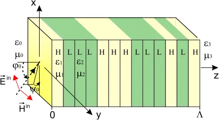
In this paper, we study the optical response of an aperiodic photonic structure formed by stacking together two different materials H and L according to the generalized Kolakoski generation scheme (see, Equation (5)). The number of generation stage of the sequence is defined as σ, and the total number of layers in the system is N. One of the possible configurations of the structure under consideration is schematically depicted in Fig. 1. Here we assume that the letters H and L denote two different layers with constitutive parameters ε1, μ1 and ε2, μ2, respectively. Thus, the studied structure is an
aperiodic layered system where layers H and L correspond to letters p and q in the K(p, q) sequence.
Throughout the paper, the aperiodic layered structure constructed on the basis of theK(p, q) sequence is called K(p, q) multilayer (or structure). The materials are assumed to be nonmagnetic ones, so
μ1 = μ2 = μ = 1. The physical thicknesses of constitutive layers H and L are defined as d1 and d2,
respectively. The total thickness of the whole structure is Λ. The outer half-spaces z ≤ 0 and z ≥Λ are homogeneous, isotropic and have parameters ε0, μ0 and ε3, μ3, respectively. Suppose that the
incident field is a plane monochromatic wave of frequency ω with perpendicular (electric-field vector
E is perpendicular to the plane of incidence) or parallel (electric-field vector E is parallel to the plane of incidence) polarization (TE- and TM-waves). The direction of the wave propagation in the input isotropic mediumz≤0 is defined by angles ϕ0 and ψ0 relative to thez axis andx axis, respectively.
In this paper, we use the transfer matrix method [11, 12, 24] to calculate spectral behaviors of aperiodic photonic structures. This method is very effective for calculations of light propagation in both the periodic and aperiodic multilayer systems, so we can apply it to calculate the transmission and reflection spectra of theK(p, q) multilayers.
3. OPTICAL RESPONSE AND OMNIDIRECTIONAL REFLECTION
Our objective here is to study main features of the optical response of both the generalized K(p, q) multilayers and heterostructures composed of cascaded Kolakoski layered systems.
Note, the reflectivity with level |R| > 0.99 for all angles of incidence and both TE and TM polarization is considered to be the criterion for acceptable ODR through the paper.
3.1. Effect of Choice of the Alphabet on the Spectral Properties
Firstly, we discuss the relation between choosing the particular alphabet A = {p, q} and the optical response of corresponding K(p, q) layered systems. For this reason we consider the ODR bands of Kolakoski structures which are built over different alphabets: A={1,2},A ={1,3},A ={1,4} and
A={1, 5}, respectively (as it is depicted in Fig. 2), keeping the same number of layers N = 30 in all systems. The individual layers H and L are considered to be quarterwave layers, i.e., their thicknesses are:
d1 = λ0
4n1, d2
= λ0 4n2.
(6)
In Equation (6)
λ0 =
2πc ω0
(7)
is a wavelength fixed in the middle of the region of interest (here λ0 = 1.2µm); n1 = √ε1μ1 = 4.7,
n2=√ε2μ2 = 1.47. So, in this case, thicknesses of layers H and L are 63.8 nm and 204.1 nm, respectively.
From our previous investigations [4, 12] it is revealed that reflectance maps for K(p, q) structures which are constructed over the same alphabet A = {p, q}, but for the different letter (p or q) as an initiator, are similar. So in what follows we will focus on the study of the optical features of K(p, q) multilayers which have letter p= 1 as the initiator.
In Fig. 2 the reflectance maps R(ϕ0, ω) plotted versus the angle of incidence ϕ0 and the
dimensionless frequencyω/ω0 are shown. Here the maps in panels (a) and (c) correspond to aperiodic
systems in which the sum of lettersp andq is odd, while the maps in panels (b) and (d) correspond to the case whenp+q is even. Everywhere in the paper the uncolored regions in figures correspond to the high-reflectance areas, where|R|>0.99.
At the normal wave incidence (ϕ0 = 0) obtained results are the same for both TE and TM
polarizations. In this case, spectra have interleaved areas with high and low average level of reflection and transmission, and are symmetric with respect to the central frequency ω0. At the same time, one
can see in Fig. 2 that the main difference between reflectance maps of multilayers with the odd and even value of p+q is the presence or absence of the PBG with the center of symmetry around the frequencyω0. Thus, when the sum of pand q is an even value the spectra demonstrates the symmetric
When the angle of incidence varies in the range 0 < ϕ0 ≤ 90, the PBG symmetry around the
frequency ω0 appears to be broken, and the photonic reflection bands experience a blue shift for both
TE and TM polarized waves as the angle of incidence rises. Remarkable that this effect becomes stronger for the higher frequencies.
At the same time, there are two significant differences between TE and TM polarizations in the case of oblique wave incidence. Firstly, for the TM polarization, the frequency shift is more significant for the lower edges of the band gaps, whereas for the TE polarization, the frequency shift is more significant for the upper edges of the band gaps. Secondly, as the angle of incidence rises the band gap width for the TM polarization decreases, while for the TE polarization it increases.
It can also be seen that the number, spectral position and width of the band gaps strongly depend on the choice of the alphabet A ={p, q}. Namely, with increasing magnitude q at fixed p = 1 (that corresponds to the optical thicknesses increasing of the corresponding “blocks” in the structure) the number of PBGs also increases, but their width decreases. We should note that only some of these PBGs are omnidirectional. In this paper, by analogy with [19] the omnidirectional PBG width is determined by the lower wavelength limit at the angle of incidence ϕ0 = 0◦, and by the upper wavelength limit at
the angle of incidenceϕ0 = 85◦. The suitable omnidirectional PBGs ranges are highlighted in Fig. 2 by
the dashed areas.
We can also see from Figs. 2(a), (b) that as the magnitude q increases from 2 to 3, the number of the ODR bands also increases from 2 to 3. All these areas shift down to the lower frequencies, and their frequency range becomes much narrower. If we continue to increase the magnitude of q (e.g., see Figs. 2(c), (d)), then the number of overall ODR bands decreases and they appear to be increasingly shifted to the lower frequencies. Therefore, we can conclude that both the frequency ranges and the
(a) (b)
(c) (d)
central frequencies of the omnidirectional band gaps significantly depend on the choice of the alphabet
A={p, q} in the Kolakoski sequence.
Besides, as demonstrated in Fig. 2, the omnidirectional band gap for the TM polarization is completely located within that one for the TE polarization. It is due to the fact that in contrast to the case of the TE polarization, as the angle of incidence increases the band gap width for the TM polarization decreases, which follows directly from the comparison of width and position of the corresponding dashed areas in Fig. 2. Therefore, the omnidirectional PBG for the TM polarization is the overall omnidirectional PBG for any polarization. So we can conclude that the criterion of appearing of the overall ODR area is the presence of the omnidirectional PBG for TM waves in the required frequency range.
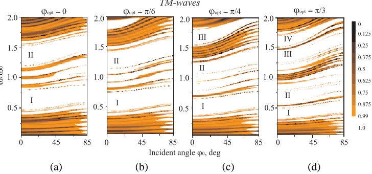
3.2. Effect of the Layers Thicknesses on the Spectral Properties
Further, we investigate the effect of the thicknesses of constitutive layers on the optical response of the aperiodicK(1, 2) structure. We discuss the case when thicknesses of the layers H and L are optimized in order to obtain the largest reflection for a given wavelength λ0 and particular angles of incidence
ϕopt:
dϕ1opt =
λ0
4n1
1− n
2 2
n21
sin2ϕopt −1
2
, dϕ2opt =
λ0
4n2
1 cosϕopt.
(8)
As an example in Fig. 3 we demonstrate the band gaps for TM polarization, which are calculated for four particular structure configurations. These four configurations are obtained for the same total number of the layers (N = 30) and the refractive indices n1 = 4.7, n2 = 1.47 but for the different
optimized thicknessesdϕ1opt and dϕ2opt of the constitutive layers.
The results presented in Fig. 3 show that when the optimized thicknesses of the layers dϕ1opt and
dϕ2opt increase, the edges and central frequencies of the “initial” PBGs (depicted in Fig. 3 as I and II)
shift down to the lower frequencies, besides some new band gaps (III and IV in Fig. 3) appear within investigated spectral range. Moreover, the bandwidth of all PBGs becomes narrower. Consequently, the bandwidth of PBGs, their number and occupied frequency region can be modulated by the thickness of the constitutive layers. So, we can determine the optimal thicknesses for which omnidirectional reflection occurs in suitable frequency ranges.
(a) (b) (c) (d)
Figure 3. Calculated reflectance maps for K(1,2) multilayers in which thicknesses of layers are optimized according to Equation (8) for the different particular angles of incidence. (a) ϕopt = 0,
dϕ1opt = 63.8 nm,d ϕopt
2 = 204.1 nm; (b) ϕopt =π/6, dϕ1opt = 64.6 nm,d ϕopt
2 = 235.7 nm; (c) ϕopt = π/4,
dϕ1opt = 65.5 nm, dϕ2opt = 288.6 nm; (d)ϕopt =π/3, dϕ1opt = 66.3 nm,dϕ2opt = 408.2 nm. In all cases there
Also as can be seen in Figs. 2, 3, under certain structure parameters the band gaps can overlap each other. So the criterion of designing ODR with the maximum photonic band gap width in cascaded heterostructures, which was proposed earlier in paper [19], can be achieved. This criterion is following: at the maximum angle of incidence ϕ0 = 85◦ for TM polarized light the upper band gap edge of the
front-standing structure overlaps the lower band gap edge of the behind-standing structure. Thus, a possibility of obtaining the broad omnidirectional band gap in cascaded Kolakoski structures should be investigated.
3.3. Photonic Heterostructures Based on Cascaded Kolakoski Multilayers
In this section we consider the main features of the optical response of the cascaded Kolakoski structures. In all cases, the total number of the layers in a heterostructure is N = 150. The obtained reflection spectra of two different heterostructures are presented in Fig. 4.
(a) (b)
Areas with localized transmission peaks
Figure 4. Calculated reflectance maps for photonic heterostructures based on cascaded Kolakoski multilayers. The dashed boxes present ODR regions. In all cases there is λ0 = 1.2µm.
Several remarkable facts can be observed in this figure. First of all, one can conclude that the broad omnidirectional band gap can be obtained by the combination into single superlattice of two classical Kolakoski K(1,2) structures made of layers with the same materials H and L and different thicknesses. Here thicknesses of individual layers H and L are optimized for angles ϕopt = 0 and ϕopt = π/4, for the front-standing and the behind-standing structures in the superlattice, respectively. In these cases we have overall omnidirectional reflection band with level of reflection |R| ≥ 0.99 which spans from 0.48ω0 to 1.55ω0 that corresponds to wavelength range 0.77µm ≤ λ ≤ 2.5µm for λ0 = 1.2µm.
Therefore, this kind of the photonic heterostructure has a very broad omnidirectional total reflection band covering whole near-infrared (NIR) spectral region (as it is known, NIR occupies approximately from 0.76µm to 2.5µm). So, we can conclude, that the proposed structure can be used as a highly efficient omnidirectional reflector in the range of the optical communication.
As the second comment, in the case when a heterostructure is composed of theK(1,3) andK(1,2) multilayers (with the same refractive indices of the quarterwave layers H and L), in Fig. 4(b) we can observe, that the frequency range and relative bandwidth of PBG (which spans from 0.35ω0 to
1.65ω0) are larger than those for previous structure. But, in this case, calculations have shown that
the reflection spectrum for TM polarization in certain spectral ranges has some transmission windows (with low magnitude of transmission|T| ≤0.1). So, the considered photonic heterostructure stands out by several narrow frequency low-intensive transmission windows and very broad ODR bandwidth.
4. CONCLUSION
In conclusion, in this paper, we have studied the ODR properties of the novel type of one-dimensional aperiodic multilayered structures formed according to the generalized Kolakoski sequence K(p, q) generation rules. In order to find their reflection spectra for both TE and TM polarizations we used the well-known transfer matrix formalism. The reflection spectra, for different choices of alphabet
A={p, q} in the Kolakoski sequence, are presented in the paper. Also, the influence of thicknesses of
the constitutive layers at fixed alphabetA={1,2}, on the omnidirectional reflection, is also discussed. The obtained results demonstrate that the generalized K(p, q) multilayers have several overall ODR bands in different frequency regions. Such omnidirectional reflectors, which are able to operate in several ranges of wavelengths, may have various potential applications.
Besides, we have shown that the omnidirectional PBG width can be enlarged by using the cascaded Kolakoski structures. Namely, combining together two Kolakoski aperiodic structures in order to form a heterostructure, a broad omnidirectional reflection band, which covered whole NIR spectral region, can be obtained.
We suppose that this kind of aperiodic structures can be used for the design of omnidirectional mirrors, waveguiding structures, multifrequency laser cavities, optical filters, and sensors.
REFERENCES
1. Maci´a, E., “Exploiting aperiodic designs in nanophotonic devices,”Rep. Prog. Phys., Vol. 75, No. 3, 036502, 2012.
2. Dal Negro, L. and S. V. Boriskina, “Deterministic aperiodic nanostructures for photonics and plasmonics applications,” Laser Photonics Rev., Vol. 6, 178–218, 2012.
3. Tuz, V. R., “A peculiarity of localized mode transfiguration of a Cantor-like chiral multilayer,” J. Opt. A: Pure Appl. Opt., Vol. 11, No. 12, 125103, 2009.
4. Fesenko, V. I., “Aperiodic birefringent photonic structures based on Kolakoski sequence,” Waves in Random and Complex Media, Vol. 24, No. 2, 174–190, 2014.
5. Vardeny, Z. V., A. Nahata, and A. Agrawal, “Optics of photonic quasicrystals,” Nature Photonics, Vol. 7, 177–187, 2013.
6. Kolakoski, W., “Self generating runs, Problem 5304,” Amer. Math. Mon., Vol. 72, 674, 1965. 7. Sing, B., “More Kolakoski sequences,” Integers, Vol. 11-B, 1–16, 2011.
8. Sing, B., “Kolakoski sequences — An example of aperiodic order,” J. Non-Cryst. Solid, Vol. 334, 100–104, 2004.
9. Kohmoto, M., B. Sutherland, and K. Iguchi, “Localization of optics: Quasiperiodic media,”Phys. Rev. Lett., Vol. 58, 2436–2438, 1987.
10. Barriuso, A. G., J. J. Monz´on, T. Yonte, A. Felipe, and L. L. S´anchez-Soto, “Omnidirectional reflection from generalized Fibonacci quasicrystals,” Optics Express, Vol. 21, No. 24, 30039–30053, 2013.
11. Tuz, V. R., “Optical properties of a quasiperiodic generalized Fibonacci structure of chiral and material layers,”J. Opt. Soc. Am. B, Vol. 26, No. 12, 627–632, 2009.
12. Tuz, V. R., V. I. Fesenko, and I. A. Sukhoivanov, “Optical characterization of the aperiodic multilayered anisotropic structure based on Kolakoski sequence,” Proc. SPIE, Vol. 8781, 87811C, 2013.
13. Fesenko, V. I., V. R. Tuz, P. P. Rocha Garcia, and I. A. Sukhoivanov, “Dispersion properties of a one-dimensional aperiodic OmniGuide structure,”Proc. SPIE, Vol. 9200, 920017, 2014.
14. Fink, Y., J. N. Winn, S. Fan, C. Chen, J. Michel, J. D. Joannopoulos, and E. L. Thomas, “A dielectric omnidirectional reflector,” Science, Vol. 282, 1679–1682, 1998.
16. Hsueh, W. J., C. T. Chen, and C. H. Chen, “Omnidirectional band gap in Fibonacci photonic crystals with metamaterials using a band-edge formalism,”Phys. Rev. A, Vol. 78, 013836, 2008. 17. Zhang, H. F., S. B. Liu, X. K. Kong, B. R. Bian, and X. Zhao, “Properties of omnidirectional
photonic band gaps in Fibonacci quasi-periodic one-dimensional superconductor photonic crystals,” Progress In Electromagnetics Research B, Vol. 40, 415–431, 2012.
18. Wang, X., X. Hu, Y. Li, W. Jia, C. Xu, X. Liu, and J. Zia, “Enlargement of omnidirectional total reflection frequency range in one-dimensional photonic crystals by using photonic heterostructures,” Appl. Phys. Lett., Vol. 80, No. 23, 4291–4293, 2002.
19. Zhang, J. and T. M. Benson, “Design of omnidirectional reflectors based on a cascaded one-dimensional photonic crystal structure,” J. Mod. Opt., Vol. 60, No. 20, 1804–1812, 2014.
20. Xiang, Y., X. Dai, and S. Wen, “Broad omnidirectional total reflectors by using the combination of Thue-Morse photonic crystal,” International Symposium on Biophotonics, Nanophotonics and Metamaterials, Metamaterials 2006, 358–361, 2006.
21. Jia, W., L. Jiang, G. Zheng, X. Li, and H. Li, “Broad omnidirectional high-precision filters design using genetic algorithm,” Optics and Laser Technology, Vol. 42, 382–386, 2010.
22. Manzanares-Martinez, J., R. Archuleta-Garcia, P. Castro-Garay, D. Moctezuma-Enriquez, and E. Urrutia-Banuelos, “One-dimensional photonic heterostructure with broadband omnidirectional reflection,” Progress In Electromagnetics Research, Vol. 111, 105–117, 2011.
23. Allouche, J. P. and J. O. Shallit, Automatic Sequences: Theory, Applications, Generalizations, Cambridge University Press, Cambridge, 2003.