Western University Western University
Scholarship@Western
Scholarship@Western
Electronic Thesis and Dissertation Repository
8-10-2017 12:00 AM
The Effect of Radial and Ulnar Length Change on Distal Forearm
The Effect of Radial and Ulnar Length Change on Distal Forearm
Loading
Loading
Ahaoiza D. Isa
The University of Western Ontario Supervisor
Dr. GJW King
The University of Western Ontario Joint Supervisor Dr. JA Johnson
The University of Western Ontario Graduate Program in Surgery
A thesis submitted in partial fulfillment of the requirements for the degree in Master of Science © Ahaoiza D. Isa 2017
Follow this and additional works at: https://ir.lib.uwo.ca/etd
Part of the Biomechanics and Biotransport Commons, and the Other Biomedical Engineering and Bioengineering Commons
Recommended Citation Recommended Citation
Isa, Ahaoiza D., "The Effect of Radial and Ulnar Length Change on Distal Forearm Loading" (2017). Electronic Thesis and Dissertation Repository. 4707.
https://ir.lib.uwo.ca/etd/4707
ABSTRACT
The effect of distal radial and ulnar length change on forearm bone loading is not well
understood during simulated dynamic wrist loading. This thesis presents two studies which
investigate the effect of these length changes on distal forearm loading under simulated dynamic
wrist motion. The first study investigates the effect of radial length change on axial loading at
the distal radius and ulna and relationship between ulnar variance and distal forearm loading.
The complex variation in axial loads in the distal radius and during length change and dynamic
wrist motion were studied and discussed. There was no correlation between native variance and
distal loads. The second study investigates the effect of ulnar change on axial loading at the
distal radius and ulna and the effect of triangular fibrocartilage ligament complex (TFCC) on this
relationship. Variation in axial loads during ulnar lengthening followed similar trends to radial
shortening and vice versa.
Keywords: Axial loading, distal radius and ulna, kienbock’s disease, ulnocarpal impaction, ulnar
variance, triangular fibrocartilage ligament complex (TFCC), wrist, forearm, biomechanics,
Co- Authorship Statement
Chapter 1
Sole Author: Diana Isa
Manuscript Review: Nina Suh, Jim Johnson, Graham King
Chapter 2
Study Design: Diana Isa, Martine McGregor, Jim Johnson, Graham King Specimen Preparation: Diana Isa, Martine McGregor
Data Collection: Diana Isa, Martine McGregor, Clare Padmore, Mark Welsh, Dan Langhor
Data Analysis: Diana Isa Statistical Analysis: Diana Isa Manuscript Preparation: Diana Isa
Manuscript Review: Nina Suh, Jim Johnson, Graham King
Chapter 3
Study Design: Diana Isa, Martine McGregor, Jim Johnson, Graham King Specimen Preparation: Diana Isa, Martine McGregor
Data Collection: Diana Isa, Martine McGregor, Clare Padmore, Mark Welsh, Dan Langhor
Data Analysis: Diana Isa Statistical Analysis: Diana Isa Manuscript Preparation: Diana Isa
Manuscript Review: Nina Suh, Jim Johnson, Graham King
Chapter 4
Sole Author: Diana Isa
Acknowledgements
I would first like to express my sincere gratitude to my supervisors, Dr. G. King and Dr. J.
Johnson for the incredible opportunity to be a part of the world class research coming out of the
Roth|McFarlane Hand and Upper Limb Centre. Their patience, motivation, enthusiasm and
dedication to excellence in research has created an environment that made this research project a
success. I would also like to thank the contribution of Dr. N. Suh whose participation and input
as part of the supervisory committee was invaluable.
I would like to express my gratitude to my research partner Martine McGregor for designing the
length change implant used in this study and exposing me not only to the nuances of engineering,
but the vast world of Spotify. I appreciated her energy and upbeat attitude in the face of setbacks
and extensive testing days.
I am grateful to the members of the HULC Bioengineering team with whom I had the pleasure of
working with during this project and whose involvement was pivotal to the success of this
project: Dan Langhor, Clare Padmore, Duncan Iglesias Jordan O’Brien and Mark Welsh. I am
grateful to Dan for not only the wealth of knowledge contributed, but uncanny ability to pick out
great take-out food, to Clare for her support with operating the motion simulator, to Duncan who
developed the novel wrist simulator this testing took place on and who was always available for
troubleshooting, to Jordan, for providing technical assistance and to Mark for his valuable
participation, exemplary work ethic and constant supply of wittiness.
To my parents and siblings who have extended their support and love even from the distance. I
Finally, to my amazing, kind, all kinds of wonderful husband Deji Ayoola, for being an
incredible pillar of support, for taking the time to learn all about forearm biomechanics just so he
could be a sounding board, for supporting my dreams and putting my needs and the needs of our
children always before his. To our beautiful children Dami and Seyi, for being so understanding
when I had to work long hours and my attention was diverted to the writing of this thesis.
The completion of this project was a combined achievement by all the aforementioned to whom I
TABLE OF CONTENTS
ABSTRACT ... I CO- AUTHORSHIP STATEMENT ... II ACKNOWLEDGEMENTS ... III TABLE OF CONTENTS ... V
1. INTRODUCTION ... 1
1.1 OSSEOUS ANATOMY OF THE FOREARM ... 1
1.1.1 OSTEOLOGY OF THE RADIUS ... 1
1.1.2 OSTEOLOGY OF THE ULNA ... 6
1.1.3 DISTAL RADIO-ULNAR JOINT OSTEOLOGY ... 8
1.2 SOFT TISSUE ANATOMY AND STABILIZERS OF THE FOREARM ... 11
1.2.1 LIGAMENTS OF THE DRUJ ... 11
1.2.2 INTEROSSEOUS MEMBRANE ... 14
1.2.3 MUSCLES OF THE FOREARM ... 16
1.3 BIOMECHANICS OF THE FOREARM AND DRUJ ... 20
1.3.1 BIOMECHANICS OF THE IOM ... 20
1.3.2 BIOMECHANICS OF THE DRUJ ... 23
1.3.3 FOREARM LOAD TRANSMISSION ... 25
1.4 DISTAL RADIUS SHORTENING ... 26
1.4.1 SHORTENING IN DISTAL RADIUS FRACTURES ... 26
1.4.2 RADIAL SHORTENING OSTEOTOMY IN KIENBOCK’S ... 28
1.4.3 CLINICAL EFFECTS OF ULNAR POSITIVE VARIANCE ... 32
1.5 CURRENT BIOMECHANICAL STUDIES ON FOREARM LOAD TRANSMISSION ... 34
1.6 RATIONALE ... 39
1.7 OBJECTIVES AND HYPOTHESIS ... 42
1.8 THESIS OVERVIEW ... 43
2. EFFECT OF RADIAL LENGTH CHANGE ON DISTAL FOREARM LOADING
DURING SIMULATED WRIST MOTION ... 58
2.1 OVERVIEW ... 58
2.2 INTRODUCTION ... 58
2.3 METHODS ... 61
2.3.1 IMPLANT DESIGN ... 61
2.3.2 AXIAL LOAD MEASUREMENT ... 64
2.3.3 SPECIMEN PREPARATION ... 65
2.3.4 SIMULATION OF MOTION AND TESTING PROTOCOL ... 72
2.3.5 METHODS AND DATA ANALYSIS ... 74
2.4 RESULTS ... 75
2.4.1 NATIVE LOADS AND ULNAR VARIANCE ... 75
2.4.2 FLEXION ... 76
2.4.3 ULNAR DEVIATION ... 80
2.4.4 DART THROW MOTION ... 84
2.5 DISCUSSION ... 88
2.6 REFERENCES ... 96
3. THE EFFECT OF ULNAR LENGTH CHANGE AND TFC INTEGRITY ON DISTAL FOREARM LOADING DURING SIMULATED WRIST MOTION ... 102
3.1OVERVIEW ... 102
3.2 INTRODUCTION ... 102
3.3METHODS ... 105
3.3.1IMPLANT DESIGN ... 105
3.3.2 AXIAL LOAD MEASUREMENT ... 107
3.3.3 SPECIMEN PREPARATION ... 107
3.3.4 SIMULATION OF MOTION AND TESTING PROTOCOL ... 110
3.3.5METHODS AND DATA ANALYSIS ... 111
3.4 RESULTS ... ………112
3.4.1FLEXION ... 112
3.4.2ULNAR DEVIATION ... 117
3.5 DISCUSSION ... 125
3.6 REFERENCES ... 132
4. CONCLUSIONS AND FUTURE DIRECTIONS ... 136
4.1OVERVIEW ... 136
4.2OBJECTIVES AND HYPOTHESES ... 136
4.3EFFECT OF RADIAL LENGTH CHANGE ON DISTAL FOREARM LOADING DURING SIMULATED WRIST MOTION ... 137
4.4THE EFFECT OF ULNAR LENGTH CHANGE AND TFCINTEGRITY ON DISTAL FOREARM LOADING DURING SIMULATED WRIST MOTION ... 138
4.5FUTURE DIRECTIONS ... 141
4.6REFERENCES ... 142
APPENDICES ... 143
List of Figures
Figure 1. 1 Radius and Ulna. ... 2
Figure 1. 2 Articulating surfaces of the Distal Radius. ... 3
Figure 1. 3 Anatomic radiographic parameters of the distal radius. ... 4
Figure 1. 4 Measurement of radiographic bow of radial shaft in coronal and sagittal planes. ... 5
Figure 1. 5 Distal ulna osteology. ... 6
Figure 1. 6 Bony osteology of the ulnar shaft. ... 7
Figure 1. 7 Proximal ulna osteology ... 8
Figure 1. 8 Axial view of the DRUJ. ... 9
Figure 1. 9 Categories of sigmoid notches. ... 10
Figure 1. 10 Configurations of DRUJ in the coronal plane ... 11
Figure 1. 11 The Triangular Fibrocartilaginous Cartilage Complex (TFCC) ... 12
Figure 1. 12 Superficial and deep limbs of the dorsal and volar radioulnar ligaments. ... 13
Figure 1. 13 The anatomic components of the IOM. ... 15
Figure 1. 14 Muscles of the volar compartment of the forearm ... 20
Figure 1. 15 Muscles of the dorsal compartment of the forearm ... 20
Figure 1. 16 Axis of rotation of the forearm (AOR). ... 21
Figure 1. 17 Change in axis of rotation(AOR) during forearm rotation ... 24
Figure 1. 18 Distal Radius Malunion. ... 27
Figure 1. 19 Distal radius shortening osteotomy for Kienbock's disease. ... 30
Figure 1. 20 Ulnocarpal impaction Syndrome ... 33
Figure 2. 1 Custom Radial Implants ... 62
Figure 2. 3 FCR approach. Pronator quadratus over the distal radius. ... 66
Figure 2. 4 Bone bridge technique radius ... 67
Figure 2. 5 Radial and ulnar spacers in cadaver specimens. ... 69
Figure 2. 6 Running locking stitch through tendon ... 70
Figure 2. 7 Wrist motion simulator. ... 71
Figure 2. 8 Radiographic image of radial and ulnar implants in-situ. ... 72
Figure 2. 9 Wrist motions evaluated. ... 74
Figure 2. 10 Radial and ulnar loads during wrist flexion n=8. ... 78
Figure 2. 11 Radial and ulnar loads with radial length change during simulated wrist motion from extension to flexion n = 8. ... 79
Figure 2. 12 Radial and ulnar loads during wrist ulnar deviation n = 7. ... 82
Figure 2. 13 Radial and ulnar loads with radial length change during simulated wrist motion from radial to ulnar deviation n = 7. ... 83
Figure 2. 14 Radial and ulnar loads with radial length change during simulated wrist dart throw motion n = 6. ... 86
Figure 2. 15 Radial and ulnar loads with radial length change during simulated wrist dart throw motion n = 6. ... 87
Figure 3. 1 Approach to Subcutaneous Border of the Ulna demonstrating Bone Bridge. ... 108
Figure 3. 2 Radial and ulnar loads during wrist flexion n = 8. ... 115
Figure 3. 3 Radial and ulnar loads with ulnar length change during simulated wrist flexion with and without the TFC intact n = 8. ... 116
Figure 3. 5 Radial and ulnar loads with ulnar length change during simulated ulnar deviation
with and without the TFC intact n = 7. ... 120
Figure 3. 6 Radial and ulnar loads during dart throw n = 6. ... 123
Figure 3. 7 Radial and ulnar loads with ulnar length change during simulated dart thower's
motion with and without the TFC intact n = 6. ... 124
List of Tables
Table 1. The volar/anterior compartment of the forearm ... 17
Table 2. The dorsal/posterior compartment of the forearm ... 18
Table 3. Litchman Classification for Kienbock’s Disease ... 31
List of Appendices
Appendix 1 Glossary of Terms ... 143
Appendix 2. 1 Graph showing radial and ulnar loads with radial length change during flexion
(Mean ± SD). ... 144
Appendix 2. 2 Graph showing radial and ulnar loads with radial length change during ulnar
deviation (Mean ± SD). ... 144
Appendix 2. 3 Graph showing radial and ulnar loads with radial length change during dart throw
Appendix 2. 4 Graph showing radial and ulnar loads with radial length change during dynamic
wrist motion (Mean ± SD). ... 145
Appendix 2. 5 Graph showing radial and ulnar loads with ulnar length change during flexion with and without the TFC intact (Mean ± SD). ... 146
Appendix 2. 6 Graph showing radial and ulnar loads with radial length change during ulnar deviation with and without the TFC intact (Mean ± SD). ... 146
Appendix 2. 7 Graph showing radial and ulnar loads with radial length change during dart throw with and without the TFC intact (Mean ± SD). ... 147
Appendix 2. 8 Graph showing radial and ulnar loads with radial length change during dynamic wrist motion with and without the TFC intact (Mean ± SD). ... 147
Appendix 2. 9 Radial and ulnar loads during wrist flexion with the TFC excised n = 8. ... 148
Appendix 2. 10 Radial and ulnar loads during ulnar deviation with the TFC excised n = 7 ... 149
Appendix 2. 11 Radial and ulnar loads during dart throw with the TFC excised n = 6. ... 150
Appendix 2. 12 Percentage load sharing with radial length change during flexion expressed as a percentage of forearm compressive loads ... 151
Appendix 2. 13 Percentage load sharing with radial length change during ulnar deviation expressed as a percentage of forearm compressive loads ... 151
Appendix 2. 14 Percentage load sharing with radial length change during ulnar deviation expressed as a percentage of forearm compressive loads ... 151
Appendix 2. 15 Percentage load sharing with ulnar length change with and without an intact TFC during flexion expressed as a percentage of forearm compressive loads ... 152
Appendix 2. 17 Percentage load sharing with ulnar length change with and without an intact TFC
during ulnar deviation expressed as a percentage of forearm compressive loads. ... 153
Chapter 1
1.
I
NTRODUCTIONThis chapter reviews the anatomy, function and biomechanics of the radiocarpal joint,
distal radioulnar joint and forearm. The clinical and biomechanical effects of radial
shortening in a malunited distal radius fracture, ulnar positive variance in ulnocarpal
impaction syndrome and ulnar negative variance in Kienbock’s disease are discussed
followed by the study rationale, objectives and hypotheses.
1.1 OSSEOUS ANATOMY OF THE FOREARM
1.1.1 OSTEOLOGY OF THE RADIUS
The radius articulates with the ulna at its proximal and distal extent causing the radius to rotate
on the ulna producing forearm supination (palm up) and pronation (palm down) in addition to
flexion and extension of the wrist. The proximal articulation is referred to as the proximal
radioulnar joint (PRUJ) and the distal articulation is referred to as the distal radioulnar joint
(DRUJ) (Figure 1.1). The distal radius consists of three articulating surfaces: the scaphoid and
lunate facets which articulate with the scaphoid and lunate respectively (Figure 1.2) and the
sigmoid notch which articulates with the distal ulna.
Figure 1. 1 Radius and Ulna.
Radius and Ulna articulating at the proximal radioulnar joint (PRUJ) and the distal radioulnar joint (DRUJ) (© D Isa).
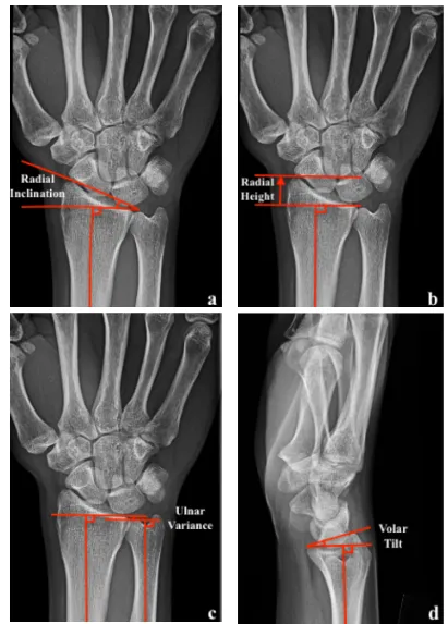
The anatomy of the distal radius is commonly described in terms of plain radiographic
measurements: radial inclination, radial length, ulnar variance and volar tilt (Figure 1.3). The
radial inclination of the distal radius articular surface averages 22o
on posteroanterior (PA)
Figure 1. 2 Articulating surfaces of the Distal Radius.
The scaphoid and lunate facets and the sigmoid notch (© D Isa).
The radial diaphysis also possesses a bow in both the coronal and sagittal plane. Schemitsch and
Richards2 devised a radiographic measurement to quantify the position and magnitude of radial
bow. With the forearm in neutral rotation on radiographs, a line is drawn from the radial
tuberosity to the ulnar border of the distal radius. A second line perpendicular to this is drawn
from the point of maximal radial bow. The height of this line is measured and compared to the
contralateral side. The radial bow is described by noting the length and position of this line (see
line X in figure 1.4). Alternatively, the bow can be described by the location of the apex of
maximal bow at the middle third of the radius and measures on average 10o
which corresponds to
Figure 1. 3 Anatomic radiographic parameters of the distal radius.
In the coronal plane, the radial bow measures 10o
with an apex radial bow at the middle third of
the radius. In the sagittal plane, the apex dorsal bow is on average 12cm distal to the radial head
and located within the proximal two-thirds of the radius averaging 5o .4
(Figure 1.4)
The proximal radius consists of the radial head, neck and tuberosity. The radial head is elliptical
with the concavity of the radial head articulating with the capitellum offset in a radial direction
from the radial neck axis.
Figure 1. 4 Measurement of radiographic bow of radial shaft in coronal and sagittal planes. (© D Isa).
1.1.2 OSTEOLOGY OF THE ULNA
The distal ulna articulates with the sigmoid notch around which the radius rotates. The
dorsomedial extension of the subcutaneous border of the ulna is called the ulnar styloid. The base
of the ulnar styloid is devoid of cartilage and is called the fovea which is the geometric center of
rotation of the DRUJ. The ulna head articulates with the articular disc of the TFCC. The dorsal
groove of the ulnar head accommodates the extensor carpi ulnaris (ECU) tendon. (Figure 1.5).
Ulnar variance is a common radiographic parameter used to assess the height of the ulna relative
to the ulnar corner of the lunate fossa on the distal radius (or relative to the length of the distal
radius) measured on PA radiographs with the wrist in neutral rotation (Figure 1. 3 c). Ulnar
variance averages -0.9 mm.5
Changes in ulnar variance with forearm position and grip has been
described accounting for subtle variations on radiographs.6,7,8
Mean maximum dynamic increase
in ulnar variance of 1.3 ± 0.5 mm occurs with gripping in pronation compared with ulnar
variance with the forearm relaxed in pronation.7
The ulna diaphysis is relatively straight in the sagittal and coronal plane at the distal and middle
third of the ulna. At the proximal third, there is a varus bow of approximately 17.7o9
as well as
proximal ulna dorsal angulation averaging 5.7 ± 2.4o
an average of 47 ± 6 mm from the
olecranon tip in the sagittal plane.10 (Figure 1.6)
Figure 1. 6 Bony osteology of the ulnar shaft.
(© D Isa)
Osteology depicting the proximal ulna dorsal angulation (PUDA) and the proximal varus bow
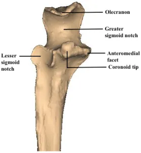
The most proximal section of the ulna is referred to as the olecranon. The olecranon and
coronoid process form the greater sigmoid notch which articulates with the distal humerus. The
coronoid consists of the anteromedial facet, the coronoid tip, the base and the lesser sigmoid
Figure 1. 7 Proximal ulna osteology
(© D Isa).
1.1.3 DISTAL RADIO-ULNAR JOINT OSTEOLOGY
Distally, the DRUJ articulation constitutes the sigmoid notch of the distal radius and the ulnar
head. The bony architecture confers 20% stability to the DRUJ.11
The majority of stability comes
from the soft tissue stabilizers which are described later in section 1.1.2.1.
The radius of curvature of the sigmoid notch is approximately 15 mm with a 47°- 80° arc of
approximately 10mm with 90° - 135° of cartilaginous coverage creating a lack of congruency
between the two surfaces.12
(Figure 1.8)
Figure 1. 8 Axial view of the DRUJ.
The radius of curvature of the sigmoid notch is greater than that of the ulnar head (© D Isa).
The morphology of the sigmoid notch was first described by Tolat and colleagues13 Four
categories of sigmoid notches were described in order of descending prevalence: Flat face, ski
slope, “C” type and “S” types, with flat face type influencing the predisposition to instability
Figure 1. 9 Categories of sigmoid notches. (© D Isa).
In order or descending prevalence: a. Flat face, b. “C” type, c. “S” type and d. Ski slope
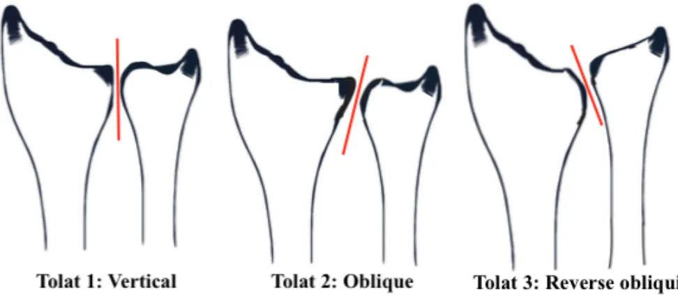
Three basic configurations of the DRUJ in the coronal plane exist: type I vertical (38%); type II
oblique (50%); or type III reverse obliquity (12%) described by Tolat and colleagues.13 Type I
has opposing surfaces parallel, in type II, the opposing joint surfaces are oblique and in type III,
the opposing joint surfaces are oriented in a reverse oblique orientation (Figure 1.10). A strong
correlation exists between obliquity and ulna variance; the more positive the ulna variance, the
Figure 1. 10 Configurations of DRUJ in the coronal plane
(© D Isa)
Types of DRUJ configurations in the coronal plane as described by Tolat.
1.2 SOFT TISSUE ANATOMY AND STABILIZERS OF THE FOREARM
The radius and ulna are linked by the annular ligament at the PRUJ proximally, the interosseous
membrane (IOM) along the diaphysis and the TFCC at the DRUJ.
1.2.1 LIGAMENTS OF THE DRUJ
Static stabilizers of the DRUJ include the TFCC and the IOM. Dynamic stabilizers of the DRUJ
include the ECU and pronator quadratus (deep head). The main soft tissue stabilizer of the DRUJ
is the TFCC. The term TFCC was coined by Palmer and Werner in 198117
series of anatomically confluent structures, each with distinct functions. The TFCC consists of
the volar and dorsal radioulnar ligaments (VRUL and DRUL), the ulnocarpal ligaments, the
ECU tendon subsheath, the articular disc and the meniscus homologue. (Figure 1.11)
Figure 1. 11 The Triangular Fibrocartilaginous Cartilage Complex (TFCC) (© D Isa)
The primary ligamentous stabilizers of the DRUJ are the volar and dorsal radioulnar ligaments
and attach to the ulna in a triangular fashion (Figure 1.12). As these ligaments extend ulnarly,
they each divide into two limbs (superficial and deep). The deep limbs attach to the fovea and the
superficial limbs extend distally and insert at the base and mid portion of the ulnar styloid.
Fractures of the ulnar styloid typically involve injury to the superficial limbs of the radioulnar
ligaments but the DRUJ remains stable if the deep fibers remain intact (Figure 1.12). The foveal
attachments are the most important components conferring stability.18
Figure 1. 12 Superficial and deep limbs of the dorsal and volar radioulnar ligaments. (© D Isa)
functions to extend the lunate facet’s articular surface providing a continuous gliding surface and
acts as part of a mobile platform for the ulnar carpus.20 There is a correlation between ulnar
variance and articular disc TFCC thickness. The more positive the ulnar variance the thinner the
articular disc/triangular fibrocartilage.21,22
The meniscus homologue (Figure 1.11) is a fold of synovium located between the articular disc,
ulnocarpal capsule, DRUL, VRUL and triquetrum and is taught in radial deviation and loose in
ulnar deviation.19,23 It helps to exert a sling effect and has been referred to as a hammock
structure stabilizing the ulnar carpus.24
The ulnocarpal ligaments consist of the ulnolunate and ulnotriquetral ligaments which originate
off the VRUL and articular disc and insert into the lunate and triquetrium respectively (Figure
1.11). The ulnocarpal collateral ligament, sometimes referred to as the subsheath of the ECU is
located ulnar to the ulnocarpal ligaments and has been shown to stabilize the ulnocarpal joint
during forearm rotation.25
1.2.2 INTEROSSEOUS MEMBRANE
The interosseous membrane (IOM) of the forearm is a robust ligamentous complex linking the
radius to the ulna. The IOM consists of a several components which include a distal membranous
portion (distal oblique bundle [DOB]),26
middle ligamentous complex (accessory band [AB] and
central band [CB]) and proximal membranous portion (dorsal oblique accessory cord and
proximal oblique cord)26,27
(See Figure 1.13). The DOB is present in 40% of individuals.26,28
forearm rotation positions and contributes to DRUJ stability.28,29,30
The CB contributes to
longitudinal stability of the forearm and prevents divergence of the radius and ulna thus
maintaining the forearm axis of rotation by tethering the bones together during pronation and
supination 27,31,32
The function of the proximal membranous portion is controversial and
unconfirmed in the literature.33,34,35
The biomechanics of the IOM is discussed in further detail in
section 1.3.1.
Figure 1. 13 The anatomic components of the IOM.
1.2.3 MUSCLES OF THE FOREARM
Muscles of the anterior compartment of the forearm are primarily involved in wrist and finger
flexion and forearm pronation.
The superficial volar compartment consists of the flexor carpi radialis (FCR), palmaris longus
(PL), flexor carpi ulnaris (FCU) and pronator teres (PT) from radial to ulnar. The intermediate
compartment consists of the flexor digitorum superficialis (FDS). The deep volar compartment
includes the flexor digitorum profundus (FDP), flexor pollicis longus (FPL) and pronator
quadratus (PQ). (Figure 1.14)
The volar compartment contains muscles which are primarily responsible for wrist, finger and
Table 1. The volar/anterior compartment of the forearm
Muscle Function
Flexor Carpi Radialis (FCR) Wrist flexion and radial deviation
Palmaris Longus (PL) Wrist flexion
Flexor Carpi Ulnaris (FCU) Wrist flexion and ulnar deviation
Pronator Teres (PT) Forearm pronation and secondary elbow
flexor
Flexor Digitorum Superficialis (FDS) Flexion of proximal interphalangeal
joints and metacarpophalangeal joint of
digits 2-5
Flexor Digitorum Profundus (FDP) Flexion of the distal interphalangeal
joints of digits 2-5
Flexor Pollicis Longus (FPL) Flexion of thumb
Pronator Quadratus (PQ) Forearm pronation
The dorsal/posterior compartment contains muscles which are primarily responsible for wrist,
Table 2. The dorsal/posterior compartment of the forearm
Muscle Function
Brachioradialis Forearm flexion
Extensor Carpi Radialis Longus (ECRL) Wrist extension and radial deviation
Extensor Carpi Radialis Brevis (ECRB) Wrist extension
Extensor Carpi Ulnaris (ECU) Wrist extension and ulnar deviation
Anconeus Assists triceps in elbow extension
Extensor Digitorum Communis (EDC) Extension of the metacarpophalangeal
joint of digits 2 - 5 and assists in wrist
extension
Extensor Digiti Minimi (EDM) Extension of the little finger
Abductor Pollicis Longus (APL) Thumb abduction and extension at
carpometacarpal joint
Extensor Pollicis Longus (EPL) Thumb extension at the interphalangeal
joint
Extensor Pollicis Brevis (EPB) Thumb extension at the
metacarpophalangeal joint
Extensor Indicis Proprius (EIP) Extension of index finger and assists in
wrist extension
The superficial dorsal compartment contains the mobile wad (brachioradialis, extensor carpi
radialis longus (ECRL) and extensor carpi radialis brevis (ECRB)), extensor carpi ulnaris (ECU)
and anconeus. The intermediate compartment consists of the extensor digitorum communis
(EDC) and the extensor digiti minimi (EDM). The deep compartment consists of the abductor
pollicis longus (APL), extensor pollicis longus (EPL), extensor pollicis brevis (EPB), extensor
indicis proprius (EIP) and the supinator. (Figure 1.15)
The ECU and its subsheath are dynamic stabilizers of the DRUJ.36 The ECU stabilizes the DRUJ
and the ulnocarpal joint in both supination and neutral forearm rotation; especially when the
TFCC is insuffficient.37
The PQ is a dynamic stabilizer of the DRUJ38,39
especially in pronation.40
The superficial head of
PQ is an important pronator while the deep head is a dynamic stabilizer of the DRUJ as
Figure 1. 14 Muscles of the volar compartment of the forearm
Figure 1. 15 Muscles of the dorsal compartment of the forearm
1.3 BIOMECHANICS OF THE FOREARM AND DRUJ
1.3.1 BIOMECHANICS OF THE IOM
The IOM is a secondary stabilizer of the DRUJ. Its’ importance for DRUJ kinematics are most
apparent when the primary soft-tissue stabilizers have been compromised at the level of the
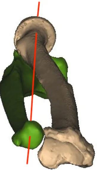
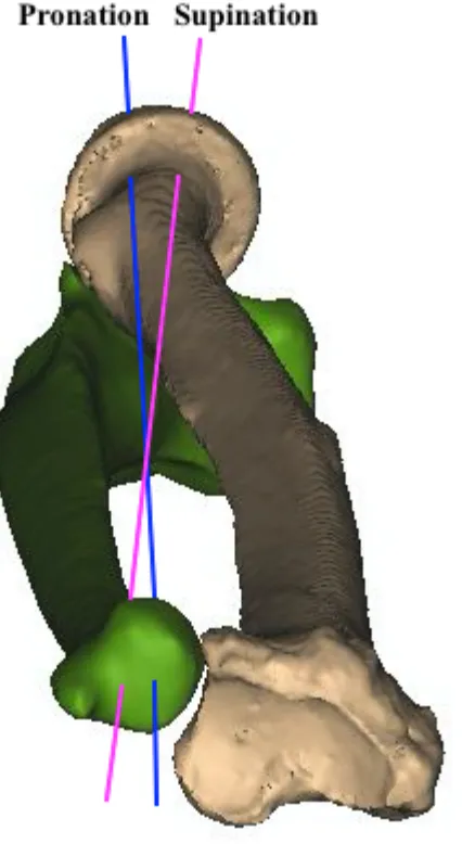
The axis of forearm rotation (AOR) runs proximally through the center of the radial head and
distally through the fovea of the ulnar head. (Figure 1.16). The change in lengths of the
components of the IOM during forearm rotation has been studied.33
The three most distal
ligaments of the IOM (CB, AB and DOB) have negligible length change during prosupination
because the ulnar attachments of these ligaments are located along the course of the AOR thus
conceptually supporting these structures as isometric stabilizers of the forearm. The proximal
membranous portion lacks isometry and is lengthened (taut) in pronation and lax in
supination.33,35
Figure 1. 16 Axis of rotation of the forearm (AOR). (© D Isa)
If the IOM is sectioned, there is resultant DRUJ instability in the absence of an intact TFCC. In
particular, the distal IOM is found to have a key stabilizing role, with the DOB of particular
importance when present.29,30,43
The distal oblique bundle of the IOM was described by Noda et
al26
and its role in DRUJ stability has been demonstrated.43,28
The DOB provides longitudinal
resistance to ulnar shortening. Arimitsu et al29
reported longitudinal resistance to ulnar shortening
was significantly greater when shortening was performed proximal to the DOB compared with a
more distal shortening. The presence of a DOB and ulnar shortening proximal to the DOB
confers greater DRUJ stability.29,30
Moreover, Watanabe et al43
demonstrated the DOB
constrained volar and dorsal instability of the radius at the DRUJ in all forearm rotation
positions. Several studies have confirmed the DOB contributes to DRUJ stability29,30,28
despite its
presence in only 40% of individuals.26,28 Biomechanical evidence suggests that individuals with a
DOB have increased stability of their DRUJ.
The IOM contributes to forearm load sharing between the radius and ulna as dissipation of forces
occur via soft tissue stabilizers as the load progresses proximally during axial loading.44,45,46
(Discussed in section 1.5 later).
The CB inserts on the proximal radial shaft and runs distally to insert on the distal ulnar shaft. It
is frequently discussed in the literature because it is considered the most functional component of
the IOM as the result of its stoutness and constancy (Figure 1.13). In particular, the CB becomes
the most important contributor to longitudinal stability of the forearm after resection of the radial
head.27,31
maintaining the forearm axis of rotation by tethering the bones together during pronation and
supination.32
In the absence of a radial head, proximal migration of the radius is resisted by load
transference to the ulna through the IOM. Increased strain in the CB of the IOM has been noted
in biomechanical studies and is responsible for the majority of longitudinal stiffness of the IOM
after radial head excision.31,47,48
The load-displacement curve on biomechanical testing
demonstrates the CB behaves structurally as a strong ligament.49
The proximal membranous portion (the proximal oblique cord and dorsal oblique accessory
cord) of the IOM do not represent isometric components and are thought to act as restraints from
excessive pronation motion of the forearm; however, the true functions of the proximal
membranous portion are controversial and unconfirmed in the literature. 33,34,35
1.3.2 BIOMECHANICS OF THE DRUJ
In most normal individuals, the total arc of pronation and supination measures between
150-180°. The differential arc of curvature between the sigmoid notch and ulnar head suggests that
prosupination not only involves rotation but also dorsovolar translation due to the cam effect at
the DRUJ.13
with the ulnar head moving dorsal and distal in pronation and volar and proximal in
supination.50
Additionally, studies have found that the DRUL is taut in pronation and thus
important in stabilizing the DRUJ in pronation while the VRUL is taut in supination and thus
more important in stabilizing the DRUJ in supination.25,42,51,52
The AOR runs proximally through
the center of the radial head and distally through the fovea of the ulnar head (Figure 1.16) and
supination (Figure 1.17).53
Figure 1. 17 Change in axis of rotation(AOR) during forearm rotation
1.3.3 FOREARM LOAD TRANSMISSION
In an earlier static biomechanical study,17
the radius distal was reported to bear 60% of the axial
load transmitted through the bones of the forearm and the ulna was thought to bear the remaining
40% in ulnar neutral wrists. TFCC excision resulted in transmission of 95% of the load through
the radius and 5% through the ulna. This demonstrates the TFCC also functions to transmit
load/load sharing between the radius and ulna. The TFCC not only plays a major role in stability
of the DRUJ, but also load transference.48
Subsequent static biomechanical studies have examined the axial load distribution between the
distal radius and ulna in static positions. It has been reported that 9 – 43 % of the total wrist load
passes through the distal ulna in neutral wrist and forearm position50,54,55,56,57 ,58,44 however, the
load distribution between the distal radius and ulna varies based on the length of the radius
relative to the ulna. When the ulnar length was increased by 2.5 mm, the forearm axial load
borne by the distal ulna increased to 42%. Conversely, when ulnar length was decreased by 2.5
mm, the axial load borne by the ulna decreased to 4%.50,54 There is a variation in axial load
transmission between the radius and ulna throughout the arc of forearm rotation. The axial load
transmitted through the distal ulna has been shown to be over 30% at 60o supination during
simulated in-vivo forearm rotation.45,59 This is controversial as some biomechanical studies have
demonstrated more load transmitted through the distal ulna at 45o and 75 o of pronation. 22,60
These studies have applied non-physiologic static loads and have not simulated in-vivo wrist
motion.
result in more force transmission through the distal ulna than a wrist with a more negative native
ulnar variance.22,55
This is likely due to the greater thickness of the TFCC in wrists with ulnar
negative ulnar variance.22,55
1.4 DISTAL RADIUS SHORTENING
Shortening of the distal radius can occur either as a sequela of distal radial fractures or as a result
of distal radius shortening osteotomy as a surgical treatment for Kienbock’s disease, avascular
necrosis of the lunate.
1.4.1 SHORTENING IN DISTAL RADIUS FRACTURES
The most common cause of axial shortening of the distal radius is due to malunion or growth
arrest following distal radius fractures. Distal radius malunion is the most common complication
of distal radius fractures with an incidence of 17 - 24%.61,62 Radial shortening of 3-6 mm or more
affects wrist function, range of motion especially in forearm rotation, and impairs clinical
outcome.63,64,65 Of the radiographic parameters, radial shortening has been associated most
frequently with unsatisfactory outcomes following distal radius fractures.66,67,68,69,70 Patients with
residual radial shortening develop wrist pain and disability due to ulnar positive variance and
subsequent clinical sequelae such as ulnar impaction syndrome (Discussed in section 1.3.3 later).
Axial shortening/loss of radial height results in a shift and transfer of load onto the ulna,
resulting in pain and limitation of grip strength, which gives rise to poor function (Figure 1.17).
Figure 1. 18 Distal Radius Malunion. (© D Isa).
Bu et al57 investigated the effect of sequential radial length change on distal ulnar loading under
static loading conditions. The authors observed differences in the effect of radial shortening on
distal ulnar loading on wrists with inherent ulnar positive variance compared with wrists with
inherent ulnar negative variance and concluded wrists with an inherent ulnar negative variance
may tolerate more radial shortening post-fracture and are less likely to have clinical symptoms of
ulnar carpal impaction.57
As discussed previously, a biomechanical study of the effect of distal radius shortening reported
that when ulnar variance was increased by 2.5 mm, the forearm axial load borne by the ulna
increased to 40%. Conversely, when ulnar variance was decreased to 2.5 mm, forearm axial load
borne by the ulna decreased to 5%.50,54 This suggests considerably altered load distribution with
relatively small changes in distal radius length. This altered loading may cause pain and
functional impairment and over time, potentially the development of degenerative wrist arthritis.
1.4.2 RADIAL SHORTENING OSTEOTOMY IN KIENBOCK’S
Avascular necrosis of the lunate, also known as Kienbock’s disease, is a relatively uncommon
disorder of the wrist. Kienbock’s disease most commonly affect male laborers aged 20 – 40
years. Both wrists are equally affected. Symptoms include activity related dorsal wrist pain,
swelling, decreased motion and reduced grip strength. Existing theories on the cause include the
pattern of arterial blood supply,73,74
disruption of venous outflow,75
ulnar negative variance,,75,76
and increased/decreased radial inclination.77,78
However, no definitive cause has been proven.
the anterior interosseous artery and palmar intercarpal arch. There are 3 patterns of interosseous
branching in the lunate, the “Y,” “X,” or “I,” patterns of blood supply with the ‘I’ pattern
demonstrating the highest risk for AVN.73 The extraosseous arterial supply to the lunate arises
from branches entering the lunate both palmarly and dorsally. The lunate is supplied by a single
palmar artery in 7 – 20% of normal individuals73,74 thus in theory placing the lunate at risk of
traumatic interruption of its vascular supply. Venous stasis due to disruption of venous outflow is
another vascular theory either as a result of the disease process or traumatic insult to vascular
outflow.75
Negative ulnar variance as a predisposing factor was first described in 1928.76 It was noted that
78% of patients with Kienbock’s in this study had negative ulnar variance compared to 23% in
the general population. It is theorized that a short distal ulna leads to increased force transmission
across the distal radius and lunate facet. However, recent biomechanical studies22 have failed to
correlate native ulnar variance with increased load transmission across the distal radius and ulna.
Furthermore, other investigators have not observed a correlation between negative native ulnar
variance and incidence of Kienbock’s79 with no significant difference in ulnar variance between
patients with Kienbock’s and the general population.78,80,81 This theory of increased load
transmission across the distal radius with ulnar negative variance has led to the common practice
of treating Kienbock’s disease with radial shortening osteotomies (See figure 1.18).57,82,83,84,85
The magnitude of shortening which is optimal and the effect of that shortening under active wrist
motion has not been determined.
The theory of radial inclination contributing to Kienbock’s has also been described as a cause for
techniques of radial opening or closing wedge osteotomies to alter inclination.86,87,88
However this
theory is controversial as radial inclination has been found to be lower than average in most
patients with Kienbock’s disease.78
Conflicting results have been published on the effect of
changing radial inclination and unloading of the radiolunate joint thus this is not as popular as
radial shortening as a treatment modality. 77,89,90
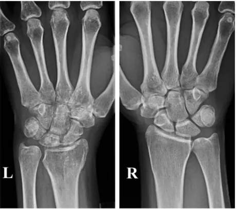
Figure 1. 19 Distal radius shortening osteotomy for Kienbock's disease.
Images of a 24-year-old woman with stage II Kienbock’s disease. a) Left wrist x-ray demonstrating sclerosis of the lunate without collapse or fragmentation. Patient has ulnar negative variance b) T1 weighted MRI image of the same wrist demonstrating a hypointense lunate indicating an avascular lunate. c) Post-operative x-ray imaging following radial shortening osteotomy to offload the lunate.
Kienbock’s disease has also been reported with various conditions including septic emboli,
corticosteroid use. No consistent correlation with any specific etiology has been demonstrated
suggesting that multiple factors are likely at play in the etiology of Kienbock’s disease.
As a result of osteonecrosis, the final stages Kienbock’s disease are lunate fragmentation and
collapse. Litchman et al91 described a 4 stage classification system for Kienbock’s disease based
on plain radiographs (Table 1) and may be useful to guide treatment.
Table 3. Litchman Classification for Kienbock’s Disease
Muscle Function
Stage 1 No X-ray changes
Signal change on MRI
Stage 2 Lunate sclerosis
Stage 3A Lunate collapse
No scaphoid palmar flexion
No loss of carpal height
Stage 3B Lunate collapse
Fixed scaphoid palmar flexion
Loss of carpal height
The treatment of Kienbock’s disease is based on the Litchman’s classification. In the early stages
before lunate collapse (stage 2 or 3a), treatment is aimed at unloading the lunate fossa which
includes radial shortening osteotomies or lunate revascularization with the use of vascularized
pedicled bone grafts.92,93,94 In later stages, treatment is aimed at addressing the carpal
malalignment, preventing further collapse and salvage procedures. These procedures include
scaphotrapeziotrapezoid fusion, scaphocapitate fusion, proximal row carpectomy, limited
intercarpal fusion and total wrist fusion based on amount of degenerative changes and patient
goals.92,93,94
1.4.3 CLINICAL EFFECTS OF ULNAR POSITIVE VARIANCE
Positive ulnar variance, can be congenital or acquired. Common causes include distal radius
malunion with shortening, radial head excision with subsequent proximal migration of the radius,
congenital positive ulnar variance, premature physeal closure of the radius or overgrowth of the
ulna due to trauma, Madelung’s deformity, infection or tumor.
Positive ulnar variance can lead to ulnocarpal impaction. The most common cause of
symptomatic ulnocarpal impaction is radial shortening due to a distal radius malunion. Ulnar
positive variance is associated with ulnar sided wrist pain, restricted ulnar deviation and forearm
rotation and development of degenerative changes due to the impaction of the ulnar head against
the ulnar carpus. These changes include erosion and perforation of the TFCC and lunotriquetral
Ulnar impaction syndrome is most frequently associated with the ulnar positive variance (Figure
1.20), however, it can also occur in wrists with either ulnar negative or neutral variance.97 Pain
often occurs with wrist pronation, forceful grip and axial loading with ulnar deviation. The
ulnocarpal stress test98 places the wrist in ulnar deviation while passively rotating the forearm
with an axial load which should reproduce the patients’ pain.
Figure 1. 20 Ulnocarpal impaction Syndrome
Images of a 20-year-old male with ulnar positive variance and symptomatic ulnocarpal
impaction. a) Left wrist X-ray demonstrating ulnar positive variance. b) Left wrist T2 weighted coronal cut demonstrating ulnocarpal impaction with subchondral bony edema (red arrows). c) Post-operative X-ray following ulnar shortening osteotomy demonstrating restoration of neutral ulnar variance.
As noted previously, changes in ulnar variance with forearm position and grip has been
described accounting for subtle variations on radiographs.6,7,8 An increase in ulnar variance of up
variance with increased ulnocarpal load with pronation and grip may explain why patients with
ulnocarpal impaction syndrome have pain with the ulnocarpal stress test.
Treatment for symptomatic ulnar impaction includes ulnar shortening osteotomy, wafer resection
of the ulnar head,99 a hemiresection interposition arthroplasty or an excisional arthroplasty.100
These procedures have been shown to decrease load transmission through the distal ulna56 and
provide satisfactory pain relief.101,102,103,104 However the optimal magnitude of ulnar shortening is
unknown. Excessive ulnar shortening can cause DRUJ incongruity105 and contribute to the late
onset of distal radioulnar joint arthritis which is commonly reported after this procedure.106,
1.5 CURRENT BIOMECHANICAL STUDIES ON FOREARM LOAD TRANSMISSION
A range of 9 – 43 % of the total wrist load has been reported to pass through the distal ulna in
neutral wrist and forearm position. 44,50,54,55,56,57,58,107.
Earlier studies by Palmer and Werner21,50,54,95 investigated loading by application of a constant
force to cadaveric wrists. The wrists were constrained by cementing a pin in the third metacarpal
to a loading frame to prevent radioulnar deviation and flexion/extension of the wrist. A constant
load of 22.2 N was applied across the wrist using weights attached to the ECRL, ECRB, ECU,
FCR and FCU. Loading of supinators and pronators and their respective contributions were not
accounted for and the effects of wrist and forearm positioning on load transmission was not
investigated. Axial loads were recorded by means of load cells in the mid-shaft of the radius and
and hence did not accurately measure load at the distal radius and ulna.44,45 This method of static
wrist loading may not accurately simulate distal radius and ulna loading during in-vivo wrist
motion.
Trumble et al108 further investigated load sharing in the radius and ulna by static loading of the
wrist in 5o and 10o of radial deviation, 5o, 15o and 15o ulnar deviation, 5o flexion and 5o, 10o, 15o,
20o, and 25 o extension and 40o of pronation and supination. An arbitrary constrained axial load
of 98.1 N was applied to the wrist using an InstronÒ materials testing machine (servohydraulic
testing system). Radial and ulnar loads were measured by load cells affixed to the shaft between
the middle and distal thirds of the radius and ulna. An average of 17% of the applied axial load
was transmitted through the ulna with an increase observed in wrist extension, ulnar deviation
and supination. Although this study expanded on earlier studies by examining the effects of wrist
and forearm position on load transmission, their method of static loading does not, in all
likelihood, accurately simulate dynamic motion. Load cells were also placed in the radial and
ulnar shaft between the middle and distal one third at a distance the distal articular surfaces and
the ROM studied was limited to a narrow range especially in flexion and extension.
In the studies listed above, the wrist was fixed in a neutral position while an axial load was
applied. The limitation of the methodology was that they did not reproduce active dynamic wrist
motion and therefore, did not account for the effect of muscle activation on wrist loading and did
not accurately simulate normal wrist kinematics. Thus, their results may not reflect in-vivo wrist
load transmission in various wrist and forearm positions. Secondly, the load cells were placed in
the mid portion of the radius and ulna, measuring the load transmission across the forearm. This
loading. 44,45,46.
The importance of the IOM in load sharing between the radius and ulna has been investigated in
two prior biomechanical studies.44,45 Loading has been shown to be equal in the proximal and
distal aspects of the radius and ulna after IOM sectioning indicating no load transfer from the
radius to the ulna after IOM sectioning.45 In another study with an intact IOM,44 in neutral elbow
position, there was an increased load registered in the proximal ulna (11.8%) compared to the
distal ulna (2.8%) indicating force transfer via the interosseous membrane.
Markolf et al44 further expanded on previous biomechanical studies on forearm load transmission
and also investigated the role of the IOM in load sharing by placing load cells in the distal ulna
and proximal radius as close as possible to the radial and ulna heads. A static constant
constrained load of 134 N was applied to the wrist using a servohydraulic testing machine while
manually rotating the forearm. This was the maximum load that could be applied without
causing structural failure; the magnitude of loading had no clinical rationale. As with previously
mentioned studies, the applied loading was constant and did not take into account variation in
loading with supination and pronation. Flexion, extension and radioulnar deviation were not
studied. The proportion of load transmission at the distal radius and proximal ulna was calculated
indirectly by subtracting the fraction that was registered by the proximal radial load-cell and
distal ulnar load cell from 100%. Since the investigators did not directly measure loading in these
areas load transfer through the IOM or other structures were not accounted for and thus the
actual loading may have been considerably different. The effect of elbow position (full
extension, 45o and 90o of flexion and varus/valgus positioning) and radial shortening on load
and radial lengthening on forearm load sharing was not investigated.
There is conflicting evidence regarding the relationship between ulnar variance and load
transmitted through the distal ulna.22,109 Bu et al57 investigated the effects of native ulnar
variance and radial shortening on load transmission. The effects of radial lengthening and ulnar
length change was not investigated. Loading was performed by application of a static axial load
of 143 N applied to dead weights to a ball joint fixed to intramedullary pins in the second and
third metacarpal. Load distribution in specimens with native ulnar positive variance was 69%
through the radius and 31% through the ulna and in wrists with ulnar negative variance and 94%
through the radius and 6% through the ulna.
However, a recent biomechanical study simulating dynamic wrist motion showed no significant
relationship between ulnar variance and load transmission.22 Harley et al22 investigated the
effects of simulated dynamic ROM on force variation in the distal radius and ulna. Load cells
were placed at the junction between the middle and distal third of the radial and ulnar shafts and
dynamic wrist motion simulated. There was no significant relationship between native ulnar
variance and the proportion of load transmission through the distal ulna. Under quasi-static
loading at neutral wrist and forearm positions, 13% of the forearm load was transmitted through
the distal ulna and during simulated dynamic motion, peak ulnar forces were 17% during wrist
flexion/extension and 20% during ulnar deviation. Loading was also higher through the distal
ulna in pronation than supination. Although this study simulated dynamic wrist motion, the
forearm muscles were stripped off the bone while the prime mover tendons were left intact
distally. The dorsal and volar palmar radioulnar joint ligaments were also sectioned in this study
lack the influence and contribution of forearm muscles and intact ligamentous stabilizers of the
wrist to load distribution in the forearm. The effect of multiplanar motion such as dart throw on
load transmission was not investigated. Dart throw motion has been shown to be an important
functional motion in performing activities of daily living.110 Load cells were placed at a distance
from the articular surface of the distal radius and ulna and were not placed in line with the central
aspect/mid axis of the radius and ulna thus, absolute loads may not represent true loads at the
distal radius and ulna. The effect of radial and ulnar length change on load sharing during
simulated dynamic motion was not investigated.
There is a correlation between ulnar variance and articular disc of the TFCC (TFC) thickness
with greater thickness of the TFC in wrists with ulnar negative ulnar variance.22,55 An earlier
study using constrained axial loading by Palmer et al17 showed resection of the TFC resulted in a
redistribution of the axial load so that the radius transmitted 95% and the ulna, 5% as opposed to
60% through the radius and 40% through the ulna with the TFC intact during static wrist loading.
A subsequent study showed excision of two thirds or more of the TFC reduced ulnar load to 3%
under static loading conditions.111
It was previously reported that a more positive ulnar variance resulted in more load being
transmitted through the distal ulna in the static loading scenario.57,109 However the correlation
between ulnar variance and loading at the distal ulna is controversial in more recent literature
using more physiologically relevant dynamic wrist motion simulators.22,57 The load distribution
between the radius and ulna varies based on the length of the radius relative to the ulna. When
ulnar variance is decreased to 2.5 mm, forearm axial load borne by the ulna decreased to 4%.
ulnocarpal joint.50,54 This load decrease is the rationale behind ulnar shortening osteotomy for
ulnar impaction syndrome.
1.6 RATIONALE
Load sharing between the distal radius and ulna remains controversial at native length and
following changes in radial and ulnar length. The aforementioned studies investigated load
sharing during wrist motion under static loading. Only one study22 has investigated loading
during simulated dynamic motion at native forearm bone length.
We chose a method of dynamic loading by suturing the prime mover tendons and connecting
them to servomotors. The use of servomotors provide more precise motion control than that of
hydraulic or pneumatic actuators used in previous studies22 that have simulated dynamic motion.
Proportional loads were applied to the other tendons based on previous electromyographic
studies of muscle activation and the relative cross sectional areas of muscles to simulate more
physiologic motion.112,113
The purpose of this research is to quantify how changes in radial and ulnar length affects distal
forearm loading as the wrist is moved through simulated dynamic wrist motion. Surgeons require
an improved knowledge of the normal forces across the distal radius and how this is altered with
radial and ulnar shortening and lengthening to influence clinical and surgical decisions.
This study aims to clarify the relationship between radial and ulnar length change and load
quantify the relationship between native ulnar variance and load distribution across the wrist.
Furthermore, the contribution of the TFC to load transfer in the distal radius and ulna with ulnar
length change during simulated dynamic wrist motion to recreate normal wrist mechanics will be
investigated.
Although the effects of distal radius and ulna length changes on load transfer between the radius
and ulna has been reported in a static situation; it is poorly understood during clinically relevant
motions. This study will help surgeons develop a biomechanical rationale for clinical decisions
related to management of Kienbock’s disease, ulnocarpal impaction syndrome, distal radius and
ulnar malunions and will have implications in the design of improved wrist implants. Hence, we
plan to quantify the load distribution between the distal radius and ulna under simulated dynamic
wrist motion for these various clinical scenarios with and without the TFC intact.
These studies herein are important in adding to the existing body of literature. Firstly, a custom
jig with a load cell will be placed close to the distal articulating surface of the radius and ulna
with placement of the load cell in line with the central axis of the radius and ulna thus gaining a
better understanding of distal radial and ulnar forces than previous studies. Secondly, a dynamic
wrist motion simulator will be utilized closely simulating in-vivo motion as opposed to static
loading methods used in most previous studies. We will add to existing body of literature by also
investigating the effects of simulated dart throwers motion on distal forearm loading with length
changes of the distal radius and ulna. Thirdly, the soft tissue envelope will be left intact thus
closely representing in-vivo conditions when compared to previous studies. Lastly, the effects of
radial and ulnar lengthening during simulated dynamic motion will be studied which has not
1.7 OBJECTIVES AND HYPOTHESIS
Objectives
1. To determine the relationship between distal forearm loading at the wrist and
radial length change during simulated dynamic wrist motion.
2. To determine the relationship between native ulnar variance and distal forearm
loading.
3. To determine the relationship between distal forearm loading at the wrist and
ulnar length change during simulated dynamic wrist motion.
4. To determine the relationship between the TFC integrity and the force
transmission through the distal ulna with ulnar length change.
Hypotheses
1. Distal radial loads will increase and distal ulnar loads will decrease with radial
lengthening and vice versa. There will be variation in loads at different wrist
positions during simulated dynamic wrist motion.
2. There will be no relationship between native ulnar variance and distal forearm
loading.
3. Distal radial loads will decrease and distal ulnar loads will increase with ulnar
lengthening and vice versa. There will be variation in loads at different wrist
positions during simulated dynamic wrist motion.
4. TFC excision will influence load transmission for each interval of ulnar length
change. Excision of the TFC during ulnar length change will decrease load
1.8 THESIS OVERVIEW
Chapter 2 is a study on the effects of distal radial length change with radial lengthening of
+1mm, +2mm and +3mm and radial shortening of -1mm, -2mm, -3mm and -4mm on load
distribution at the wrist joint between the distal radius and ulna during simulated wrist ROM.
This study will clarify the effects of radial shortening osteotomy for reducing load across the
radiocarpal joint for treatment of Kienbock’s disease. The effect of radial shortening after distal
radial fractures on distal forearm loading will also be better understood.
Chapter 3 is a study on distal forearm loading with ulnar lengthening of +1mm, +2mm and
+3mm and ulnar shortening of -1mm, -2mm, -3mm and -4mm during simulated wrist ROM to
clarify the effects of ulnar shortening osteotomy for reducing load across the ulnocarpal joint for
treatment of ulnocarpal impaction. The contribution of the TFC to load sharing will also be
studied.
1.9 REFERENCES
1. Loredo RA, Sorge DG, Garcia G. Radiographic evaluation of the wrist: A vanishing art.
Semin Roentgenol. 2005;40(3):248-289. doi:10.1053/j.ro.2005.01.014.
2. Schemitsch EH, Richards RR. The effect of malunion on functional outcome after plate
fixation of fractures of both bones of the forearm in adults. J Bone Joint Surg Am.
1992;74(7):1068-1078.
3. Firl M, Wünsch L. Measurement of bowing of the radius. J Bone Joint Surg Br.
2004;86(7):1047-1049. doi:10.1302/0301-620X.86B7.14294.
4. Rupasinghe SL, Poon PC. Radius morphology and its effects on rotation with contoured
and noncontoured plating of the proximal radius. J Shoulder Elb Surg.
2012;21(5):568-573. doi:10.1016/j.jse.2011.03.015.
5. Schund FA, Linscheid RL, An KN, Chao EYS. A Normal Data Base of Posteroanterior
Roentgenographic Measurements of the Wrist. Curr Concepts Rev. 1992.
6. Friedman SL, Palmer AK, Short WH, Mark Levinsohn E, Halperin LS. The change in
ulnar variance with grip. J Hand Surg Am. 1993;18(4):713-716.
doi:10.1016/0363-5023(93)90325-W.
7. Jung JM, Baek GH, Kim JH, Lee YH, Chung MS. Changes in ulnar variance in relation to
forearm rotation and grip. J Bone Joint Surg Br. 2001.
8. Tomaino MM. The importance of the pronated grip x-ray view in evaluating ulnar
variance. J Hand Surg Am. 2000;25(2):352-357. doi:10.1053/jhsu.2000.jhsu25a0352.
9. Clement H, Pichler W, Tesch NP, Windisch G. The influence of lateral and anterior
ANATOMICAL CADAVER STUDY. :836-838. doi:10.1302/0301-620X.89B6.18975.
10. Rouleau DM, Faber KJ, Athwal GS. The proximal ulna dorsal angulation: A radiographic
study. J Shoulder Elb Surg. 2010;19(1):26-30. doi:10.1016/j.jse.2009.07.005.
11. Stuart PR, Berger RA, Linscheid RL, An KN. The dorsopalmar stability of the distal
radioulnar joint. J Hand Surg Am. 2000;25(4):689-699. doi:10.1053/jhsu.2000.9418.
12. Ekenstam F a. Anatomy of the distal radioulnar joint. Clin Orthop Relat Res.
1992;(275):14-18.
13. Tolat AR, Stanley JK, Trail IA. A cadaveric study of the anatomy and stability of the
distal radioulnar joint in the coronal and transverse planes. J Hand Surg Br. 1996;21(5).
14. Daneshvar P, Willing R, Pahuta M, Grewal R, King GJW. Osseous Anatomy of the Distal
Radioulnar Joint: An Assessment Using 3-Dimensional Modeling and Clinical
Implications. J Hand Surg Am. 2016;41(11):1071-1079. doi:10.1016/j.jhsa.2016.08.012.
15. Garcia-Elias M, Pitágoras T, Gilabert-Senar A. Relationship between joint laxity and
radio-ulno-carpal joint morphology. J Hand Surg Am. 2003;28 B(2):158-162.
doi:10.1016/S0266-7681(02)00364-9.
16. Sagerman SD, Zogby RG, Palmer AK, Werner FW, Fortino MD. Relative articular
inclination of the distal radioulnar joint: A radiographic study. J Hand Surg Am.
1995;20(4):597-601. doi:10.1016/S0363-5023(05)80275-8.
17. Palmer AK, Werner FW, Eng MM. The triangular fibrocartilage complex of the
wrist-Anatomy and function. J Hand Surg Am. 1981;6(2):153-162.
doi:10.1016/S0363-5023(81)80170-0.
18. Haugstvedt J-R, Berger RA, Nakamura T, Neale P, Berglund L, An K-N. Relative
dynamic stability of the distal radioulnar joint. J Hand Surg Am. 2006;31(3):445-451.
doi:10.1016/j.jhsa.2005.11.008.
19. Nakamura T, Yabe Y. Histological anatomy of the triangular fibrocartilage complex of the
human wrist. Ann Anat. 2000;182(6):567-572. doi:10.1016/S0940-9602(00)80106-5.
20. Nakamura T, Yabe Y, Horiuchi Y. Dynamic changes in the shape of the triangular
fibrocartilage complex during rotation demonstrated with high resolution magnetic
resonance imaging. J Hand Surg Br. 1999;24(3):338-341. doi:10.1054/jhsb.1998.0216.
21. Palmer a K, Glisson RR, Werner FW. Relationship between ulnar variance and triangular
fibrocartilage complex thickness. J Hand Surg Am. 1984;9(5):681-682.
doi:10.1016/S0363-5023(84)80013-1.
22. Harley BJ, Pereria ML, Werner FW, Kinney DA, Sutton LG. Force variations in the distal
radius and ulna: Effect of ulnar variance and forearm motion. J Hand Surg Am.
2015;40(2):211-216. doi:10.1016/j.jhsa.2014.10.001.
23. Ishii S, Palmer a K, Werner FW, Short WH, Fortino MD. An anatomic study of the
ligamentous structure of the triangular fibrocartilage complex. J Hand Surg Am.
1998;23:977-985. doi:10.1016/S0363-5023(98)80003-8.
24. Nakamura T, Yabe Y, Horiuchi Y. Functional anatomy of the triangular fibrocartilage
complex. J Hand Surg Br. 1996;21(5):581-586.
25. DiTano O, Trumble TE, Tencer AF. Biomechanical function of the distal radioulnar and
ulnocarpal wrist ligaments. J Hand Surg Am. 2003;28(4):622-627.
doi:10.1016/S0363-5023(03)00183-7.
26. Noda K, Goto A, Murase T, Sugamoto K, Yoshikawa H, Moritomo H. Interosseous
Hand Surg Am. 2009. doi:10.1016/j.jhsa.2008.10.025.
27. Skahen JR, Palmer AK, Werner FW, Fortino MD. The interosseous membrane of the
forearm: anatomy and function. J Hand Surg Am. 1997;22(6).
doi:10.1016/S0363-5023(97)80036-6.
28. Kitamura T, Moritomo H, Arimitsu S, et al. The biomechanical effect of the distal
interosseous membrane on distal radioulnar joint stability: A preliminary anatomic study.
J Hand Surg Am. 2011;36(10):1626-1630. doi:10.1016/j.jhsa.2011.07.016.
29. Arimitsu S, Moritomo H, Kitamura T, et al. The stabilizing effect of the distal
interosseous membrane on the distal radioulnar joint in an ulnar shortening procedure: a
biomechanical study. J Bone Joint Surg Am. 2011;93(21):2022-2030.
doi:10.2106/JBJS.J.00411.
30. Moritomo H. The distal interosseous membrane: Current concepts in wrist anatomy and
biomechanics. J Hand Surg Am. 2012;37(7):1501-1507. doi:10.1016/j.jhsa.2012.04.037.
31. Hotchkiss RN, An K-N, Sowa DT, Basta S, Weiland AJ. An anatomic and mechanical
study of the interosseous membrane of the forearm: pathomechanics of proximal
migration of the radius. J Hand Surg Am. 1989;14(2 Pt 1):256-261.
32. Moritomo H, Murase T, Arimitsu S, Oka K, Yoshikawa H, Sugamoto K. The in vivo
isometric point of the lateral ligament of the elbow. J Bone Joint Surg Am.
2007;89:2011-2017. doi:10.2106/JBJS.F.00868.
33. Moritomo H, Noda K, Goto A, Murase T, Yoshikawa H, Sugamoto K. Interosseous
Membrane of the Forearm: Length Change of Ligaments During Forearm Rotation. J
Hand Surg Am. 2009;34(4):685-691. doi:10.1016/j.jhsa.2009.01.015.