E-Shaped Wide Band Microstrip Array
Antenna for Wireless Communication Systems
Siddhartha Pal
1, Kousik Roy
1, Atanu Nag
2, Adarsh Kumar Tiwary
1Department of Electronics and Communication Engineering, Asansol Engineering College, Asansol, West Bengal, India1
Modern Institute of Engineering and Technology, Hooghly, West Bengal, India2
ABSTRACT: A novel idea for improvement of bandwidth in microstrip antenna is explained in this paper. The initiation of E-shaped microstrip patch antenna enhances the bandwidth by 13% in comparison to rectangular antenna of 3.6% at 8-9GHz frequency. The recommended antenna offers a significant amount of return loss i.e. S11
characteristics and impedance performance. The design constant of antenna comprises single layer thickness of 2mm along with functioning frequency of 2.5 GHz. The design was optimized to attain the excellent probable outcome. The positive features of choosing E-shape antenna from other antennas is because of its low volume, low profile planar configuration, easiness in mounting, light weight and less fabrication cost. The main functions of this antenna incorporate remote sensing, biomedical application, mobile radio satellite and wireless communication. To conclude, the functioning of the designed antenna was examined in term of gain, return loss, VSWR, and radiation pattern.
KEYWORDS: E-shaped Antenna, Wireless Communication, IE3D.
I. INTRODUCTION
Microstrip patch antenna is very important for wireless communication ever since it was first shown in the year of 1886 by Heinrich Hertz and its practical appliance by Gugliemo Marconi in 1901. Microstrip patch antenna have been famous for its benefits like light weight, low fabrication cost, mechanically tough when mounted on firm surfaces and ability of dual and triple frequency performances. Nevertheless, narrow bandwidth is one of the main drawbacks for this kind of antenna. Various methods have been implemented to conquer this problem such as enhancing the substrate thickness, establishing parasitic elements i.e. co-planar or stack configuration, or by adjusting the patch’s shape itself. Amending patch’s shape occupies designing an E-shaped patch antenna by cutting two slots from a rectangular shape. This occurrence effects in improvement of bandwidth, gain and return loss of the antenna [3]. In comparison to the U-slot microstrip patch antenna, the E-shaped patch antenna is easy to construct.
Modern Institute of Engineering and Technology, Bandel, Hooghly 712123, West Bengal, India.
II. ANTENNA CONFIGURATION
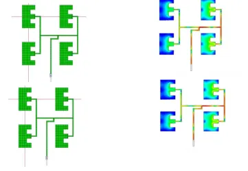
Fig.1(a) Geometry of E-shape Antenna Fig.1(b).E-shape Antenna Array
The antenna geometry demonstrated in Fig.1(a) has only one patch, which is easier than conventional broad-band microstrip antennas. The antenna is devised with the help of edge feed to resonate at frequency of 2.4 GHz. The patch is accumulated on a glass substrate with comparative permittivity, = 2.2.Here length of patch and height of patch are 27.4mm and 2mm respectively. The antenna shown above in Fig.1(b) includes the sub - array designing of E- Shaped antenna where four same ingredients are built to construct a 2x2 sub array. The feeding strip is tied with another vertical strip that goes through an air layer associating a 50 Ohm microstrip feed line on a ground substrate.
of the antenna, including phase delay among elements, variation in the radiation features of distinctive radiating structure in an array, modification in the geometry of the array and by altering the inter-element spacing.
III. DESIGN SPECIFICATIONS
A. 1. Calculation of patch width (w) of determined by the formula
0
2
2
r r1
v
w
f
(1)Where, v0= speed of light in free space,
r=dielectric constant of patch.2. Calculation of effective dielectric constant
reff computed by the formula1 2
1
1
1 12
2
2
r r reffh
w
(2) Here, h and w denote the height of the patch, width of the patch respectively.3. Determination of increment of patch length ( ) computed by the formula
(
0.3)(
0.264)
0.412
(
0.258)(
0.8)
reff reff
w
h
l
w
h
(3)4. Calculation of patch length (l) computed by the formula
0 0
1
2
2
r reffl
l
f
(4)Here,
f
r,
reff ,
0,
0 signify the resonant frequency of antenna, effective dielectric constant The essentialparameters for the design of E-Shape Microstrip Patch Antenna Array are as follows f=2.4 GHz,
r= 2.2, h=2mm.Calculating the design parameters we get w=4.94cm,
reff =1.84, l= 0.931cm, l=2.74cm.IV. PERFORMANCE EVALUATION
Modern Institute of Engineering and Technology, Bandel, Hooghly 712123, West Bengal, India.
Fig. 2 (a) Return Loss characteristics of E-shape Antenna Array
Fig. 2 (b) VSWR characteristics of E-shape Antenna
Fig.2(c) 3-D Directivity Pattern for E-shape Antenna Array Fig.2 (d) 3-D Gain Pattern for E-shape Antenna Array
The above diagram in Fig. 2 (c) presents the three dimensional directive pattern of the antenna. Antenna directivity is the ratio of maximum radiation intensity (power per unit surface) emitted by the antenna in the maximum direction divided by the intensity radiated by a hypothetical isotropic emitting similar total power as that antenna. The above Fig. 2 (d) illustrates the three dimensional pattern of gain in dB scale for the antenna. Gain as a parameter computes the directionality of a specified antenna. An antenna with a low gain produces radiation in all directions uniformly, while a high-gain antenna will specially radiate in specific directions.
V. DISCUSSION
REFERENCES
[1] W.L. Stutzman and G.A. Thiele, “Antenna Theory and Design”, 2nd ed. New York: Wiley, 1998
[2] Constantine A. Balanis, “Antenna Theory Analysis and Design”, 2nd Edition, John Wiley & Sons, New York. [3] Girish Kumar, K. P. Ray, “Broadband Microstrip Antennas”, 1st Edition, Artech House, 2003.
[4] Caner Acar , Mert Kulaç , Taha Imeci, “High Gain Reverse E-Shape Patch Antenna” 28th Annual Review of Progress in Applied
Computational Electromagnetics, April 10-14, 2012.
[5] Alka Verma, “ANALYSIS AND DESIGN OF E SHAPED PATCH ANTENNA IN X BAND”, International Journal of Advanced Engineering Technology,E-ISSN 0976-3945, 2009.