Seismic Performance Evaluation of RC
Structure against Progressive Collapse under
Different Column Removal Scenario
Divya T.H.1, Nikhil R.2
M.Tech Scholar, Dept. of Civil Engineering, Universal Engineering College, Thrissur, Kerala, India1
Asst. Professor, Dept. of Civil Engineering, Universal Engineering College, Thrissur, Kerala, India 2
ABSTRACT: Progressive collapse is a nonlinear dynamic event which occurs when load carrying members are
removed. In the present study, a progressive collapse assessment according to GSA and DoD guidelines are carried out for a G+7 RCC building. Using nonlinear dynamic analysis with joshua earthquake data. This dynamic phenomena created due to various human activities and natural phenomena adversely affect buildings, its occupants and human life. Aim of this study is to understand performance of RC building under the column removal scenario during an earthquake data. Nonlinear direct integration analysis is performed using ETABS 17.0.1 to understand response of a structure during seismic action. For this study column removal locations considered are corner, intermediate and perimeter of the plans. Beams are considered for this study optimum. L/D ratio of Beam is obtained as per IS 456 -2000, for 3m and 4m span L/D ratio 12 is considered and L/D ratio 10 is considered for 6m span beam. DCR value is less than 2.
KEYWORDS: progressive collapse; catenary action; aspect ratio; L/D ratio; DCR value; plastic hinge.
I.INTRODUCTION
Progressive collapse is described as the spread of an initial local failure from element to element due to lack of structural continuity, ductility and redundancy that leads to partial or total collapse of a structure.Department of defense (DoD) and general service administration (GSA) issue guidelines for design of structures (both RC and steel) to resist progressive collapse. Both documents (GSA 2003, DoD 2005) are recommended to be applied to, low to medium rise structure with common structural system. Abnormal loads such as earthquake, gas explosions and vehicle collision tend to lead local failure in structures. If local failures are uncontrolled, they can lead to partial or full progressive collapse of structure.
collapse of the upper stories as shown in figure 1 (b)
Several other notable events for progressive collapse of structures which are:-
L‘Ambiance Plaza at Bridgeport, Connecticut
U.S. Marine Barracks Lebanon
Kansas City Hyatt Regency Hotel Walk Way Collapse
Skyline Plaza – premature formwork removal
Civic Arena Roof collapse
World Trade Centre
Khobar Towers
Jackson Landing Skating Ring – Excessive ice load
(a) (b)
(a) (b)
Fig. 2Collapse of (a) U.S Marine Barracks (b) Skyline Plaza
II. GENSIS OF PROGRESSIVE COLLAPSE
Progressive collapse occurs in the building structure under the abnormal loads. Abnormal load resistance criteria is not considered in the normal building design. Therefore, when buildings are subjected to such type of loads, progressive collapse may take place. The potential of abnormal loads that can trigger the progressive collapse are classified as follows:-
PRESSURE LOADS
• Internal gas explosion
• Blast loads
• Extreme value of wind pressure
III.OBJECTIVES
The objective of the present study is to analyses the effect of span length and beam depth in progressive collapse of multistory RC buildings. It also includes the behavior of building under critical member loss using Joshua earthquake data.
IV. DETAILS OF HYPOTHETICAL CASES
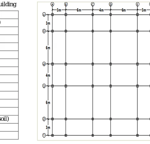
To study the effect of column removal condition on the structure, hypothetical case of G+7, storied reinforced concrete building with special moment resisting frame is considered. Total height of building is 24 m and all floor height are 3m. Height of base to plinth is taken as 2.4 m. Aspect ratio L/B= 1. (Length and breadth of building 22 m). Building is to be located in seismic zone 5, as per IS: 2016. Hypothetical buildings are designed as per IS 456-2000, IS 1893-2016, IS 875 -2000, IS 13920-1893-2016, SP 34, GSA (2013), and DoD (2010).
Table 1 Details of Properties in Hypothetical Building
Fig. 3 Plan of Hypothetical Case Study Building
Column removal locations as per guidelines where corner, intermediate and perimeter of the building. Column removal stories are ground, middle (4th floor) and roof are considered for this study. Progressive collapse analysis is based on the GSA and UFC guidelines.As per IS 1893 – 2016 Earthquake Load along X direction (EQX) and Earthquake Load along Y direction (EQY) acting and load combinations are considered for design of structural elements 1.5 (DL+LL) , 1.2 (DL+LL±EQX) , 1.2 (DL+LL±EQY) ,1.5 (DL±EQX) ,1.5 (DL±EQY) ,0.9 DL ± 1.5 EQX and 0.9 DL ±1.5 EQY.The earthquake data selected should have higher magnitude; it should have the ability to cause high structural destruction and damage. Selected earthquake data name is Landers in 1992 station at Joshua with magnitude 7.28 and PGA was 0.3629.
MATERIAL PROPERTIES
Grade of concrete M 34.5 (MPa)
Unit weight of concrete 23.5 kN/m²
Modulus of elasticiy 29600 MPa
Grade of steel Fe 413 (MPa)
Density of concrete 25 kN/m3
Wall thickness 200 mm
LOADS IS 875 PART 2
Live load on all floor 3 kN/m²
Live load on roof 1.5 kN/m²
Floor finish 1 kN/m²
SEISMIC DETAILS IS 1893-2016
Zone factor Z 0.36
Site type lll (soft soil)
Importance factor 1.5
(a) (b)
(c)
Fig. 4 Reinforcement details of columns(a)500 x 500 mm and (b) 450 x450 mm and (c) Beam as per GSA guidlines
Table 2 Building Details
Column size: - 500X500 Main bar: - 16 T20
Ties: - 8T20c/c
Column size: - 450X450 Main bar: - 16 T20
Ties: - 8T20c/c
SPAN (m)
COLUMN (mm) BEAM (mm) SLAB
(mm)
WALL LOAD (kN/m²)
3
GF - 4th : 450 x 450 (interior column) & 400 x 400 (exterior
column) 5th - ROOF : 400X400
(Exterior & interior column
300x250 100 11
4 300x350 110 9.6
details, local site conditions of earthquake recording station, other important and relevant engineering parameters. Earthquake is a probability case of progressive collapse. Seismic analysis provided in FEMA 356 consist of four different type of analysis procedures for seismic performance based evaluation is same progressive collapse analysis are
NON LINEAR ANALYSIS
1. NON LINEAR DYNAMICANALYSIS
2. NONLINEAR STATIC ANALYSIS
LINEAR ANALYSIS
1. LINEAR DYNAMIC ANALYSIS
2. LINEAR STATIC ANALYSIS
V. MODELS AND COLUMN REMOVAL LOCATIONS
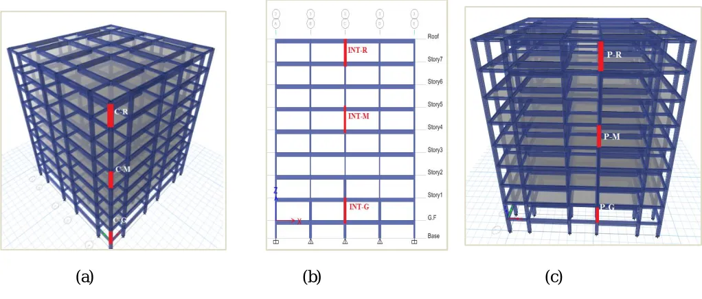
The column removal location at (a) corner indicated as C-G, C-M, and C-R are corner ground, corner medium and corner roof respectively(b) INT-G, INT-M and INT-R for intermediate ground, intermediate medium and intermediate roof respectively. (c) P-G, P-M and P-R for perimeter ground, perimeter medium and perimeter roof respectively as shown in figure 5. Column removal locations considered as per General ServiceAdministration and Department of Defense guidelines.
(a)
(b) (c)
VI.METHODOLOGY
As per guidelines following three procedures are used for analysing structures subjected to progressive collapse: first one, Linear static procedure also called LSP which is simplest method in this method material is assumed to be linearly elastic; no geometric nonlinearity is considered; and structure is supposed to experience small deformation. Second one is nonlinear static analysis also called NSP, in which both geometric and material nonlinearities are considered; third case is nonlinear dynamic procedure also called NDP which involves inertia and damping effects and it gives most accurate results. In the current study the method used is nonlinear dynamic procedure. The main difference between nonlinear and linear dynamic analysis is that in nonlinear dynamic case, the structural elements are allowed to enter the inelastic range.
Following procedure were carried out for this study:
ETABS 17.0.1 software used for modelling
Apply load combination as per progressive collapse guidelines
Determine the forces present at equilibrium in each column to be removed.
Static nonlinear analysis case are used as starting condition for column removals
Find the gravity load carrying capacity of vertical members (i.e. column) to be removed
Remove the column and corresponding axial force of removed columns to be provided as point load
Remove the point load using time history ramp function
Evaluate the result based on demand capacity ratio (DCR) for beams
VII. RESULT AND DISCUSSION
VII. DEMAND CAPACITY RATIO
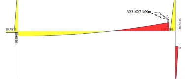
According to GSA (20013) guidelines the DCR, of the member force and the member strength, is a measure to determine the failure of main structural member by linear dynamic procedure. Figure shown the maximum bending moment diagram
FIG. 7 Maximum Bending Moment under Column Removal Scenario
D.C.R= QUD/ QCE
Where, QUD = Acting force or demand determine (shear, axial force, bending moment, and possible combined forces
QCE = Apparent ultimate capacity (shear, axial force, bending moment, and possible combined forces
DCR < 2.0 for typical structural configurations and DCR < 1.5 for atypical structural configurations. The current study model is typical
Where, QUD = 322. 627 kNm from the software
QCE =>Mulimit = 0.138 x fck x b x d 2
= 0.138 x 34.5 x 300 x 5652
=455.9 kNm
DCR < 2
The maximum DCR value obtained from column removal of intermediate case at ground floor level. The value of demand moment is 322.627 kNm obtained since 5 sec. For the case study a maximum time of 5 second is considered, the number of output time steps were taken as 50 and output time step size 0.1 second. DCR value is less than 2, building is safe condition occur.
VIII. CONCLUSION
than 2, in the case of 3m and 4m span are found ideal and L/D ratio may vary from 10 to 12, remaining range is not safe. For 6 m span, only L/D=10 is found safe. In seismic zone it is better not to consider L/D above 10. Progressive collapse reduce the rigidity of the structure. Provide adequate joint and adequate reinforcement detailing. Span of the structural element should be adequate as per the guidelines given by the standard codes. For future studies all spans may be given same depth i.e. here the versatile condition is L/D=15 in 6m span.
IX. FUTURE WORK SUGGESTIONS
• Study on typical 8 m span building with L/D ratio of beam 10,12and 15
• Study the same case in steel building
• Study on irregular structure may be a good option for future work. But for this case rather than span and depth, flanged or doubly reinforced sections may be considered for effective results.
REFERENCES
[1] David Stephen et al. (2018) “An evaluation of modelling approaches and column removal time onprogressive collapse of building” J. of
Constructional Steel Research (2018) 07.019
[2] H.M. Salemet al. (2011). “Toward An Economic Design of Reinforced Concrete Structures against Progressive Collapse." J. of Structural
Engg33 (2011) 3341–3350
[3] Kamal Alogla (2016). “A new mitigation scheme to resist progressive collapse of RC structures" J. of structural engineering Engg 125 (2016)
533-545
[4] Li et.al (2011) “An improved tie force method for progressive collapse resistance design of reinforced concrete frame strutures” J. of
Structural Engg 33 (10): 2931-2942
[5] NiloufarMashhadiali et al. (2016). “Dynamic Increase Factor for Investigation of Progressive Collapse Potential in Tall Tube – Type
Buildings." J. of Structural Engg 10.1061/ (ASCE) CF.1943-5509
[6] Sasani, M. (2008). “Response of a reinforced concrete infilled-frame structure to removal of two adjacent columns.” J. of structural
engineering Engg 30 (10): 248-2491
[7] Sasani, M., Bazan, M., and Sagiroglu, S. (2007). “Experimental and analytical Progressive collapse evaluation of anactual reinforced concrete
Structure.” J. of structural engineering Engg 104 (6): 731-739
[8] Sasani, M., Kazemi, A., Sagiroglu, S., and Forest, S. (2011). “Progressive Collapse resistance of an actual 11-story structure subjected to
severe Initial damage.” J. of structural engineering Engg10.1061/ (ASCE) ST.1943-541X.0000418.
[9] Sasani, M., and Kropelnicki, J. (2008). “Progressive collapse analysis of an RC structure.” The Structural Design of Tall and Special Buildings,
17:1, 757-771
[10] Sasani, M., and Sagiroglu, S. (2008). “Progressive collapse resistance of Hotel San Diego.” J. of structural engineering Engg 134(3), 478-488
[11] Sasani, M., and Sagiroglu, S. (2010). “Gravity load redistribution and Progressive collapse resistance of a 20-story RC structure following loss
of an interior column.” J. of structural engineering Engg ACI
[12] Wei – jian Yi et al. (2018). “Experimental Study on Progressive Collapse – Resistant Behavior of Reinforced Concrete Frame Structures “J.
of structural engineering Engg ACI
[13] U.S General Service Administration, Progressive collapse analysis and design guidelines for new federal office buildings and major
modernization projects