ISSN (Print) : 2347 - 6710
I
nternationalJ
ournal ofI
nnovativeR
esearch inS
cience,E
ngineering andT
echnologyVolume 3, Special Issue 3, March 2014
2014 International Conference on Innovations in Engineering and Technology (ICIET’14) On 21st&22ndMarch Organized by
K.L.N. College of Engineering, Madurai, Tamil Nadu, India
ABSTRACT—In this paper fuzzy based three phase single stage trasformerless grid connected PV system is proposed. Due to the energy demand and GHG emission, renewable energy sources are become more popular. Nowadays renewable energy sources are mostly used in Distributed generation. Solar power generation system become more popular due to the suitability in distributed power generation .Three phase single stage current source inverter based trasformerless grid connected PV system uses a single converter unit (DC/AC CSI). Fuzzy based MPPT used for maximum power extraction from solar system. PR control technique used in voltage and current control loops. The three phase single stage grid connected PV system is simulated using MATLAB/SIMULINK and experimental result are presented
KEYWORDS– Current Source Inverter (CSI), Maximum Power Point Tracking (MPPT), Proportional Resonant control, Green House Gas (GHG)
I.INDRODUCTION
A two stage grid connected PV system uses two conversion stage: First stage is DC to DC conversion (using chopper circuit) for boosting and conditioning and the second stage is DC to AC interfacing to the grid. This tow stage technique suffers from reduced efficiency higher cost and large size. In this proposed method the chopper circuit is eliminated, instead of the chopper circuit a double tuned resonant filter is used. The overall efficiency of the system is increased by a Maximum Power Point Tracking (MPPT) system is controlled by fuzzy logic controller.Using of voltage source inverter increase the necessity of using a bulky of transformer. In proposed method instead of voltage source inverter a current source inverter is used. A modified carrier based modulation technique is used in current source inverter. The current source inverter eliminates the transformer.
system. The two stage grid connected PV system shown in fig.1 and single stage grid connected PV system shown in fig.2In conventional method the Voltage source inverter was commonly used due the simplicity and availability but the voltage source inverter requires bulky of transformer [1] and Maximum Power Tracking system used perturbing and observing algorithm. For harmonics reduction the system used a large inductive filter. More multilevel inverter have been used to improve the ac-side waveform quality and reduce the electrical stress on the power switches and reduce the power losses due to a high switching frequency [2][3] but the this merits are achieved at the expense of a more complex PV system. They used large and bulky transformer which increase the losses and reduce the system efficiency and also increase the cost of the system. The transformer is eliminated by replacing the voltage source inverter by current source inverter this method was discussed in [4] but this system used two stage converter circuit the chopper and inverter circuit. This system fails to implement the MPPT system. In [5] the efficiency of the system improved by MPPT system and current source inverter but the filter circuit not effective only LC filter was used. The single stage transformerless PV system explained in [6] it used MPPT system with hill clamping algorithm but this algorithm also not effective in changing weather condition. For harmonics reduction it used a low pass filter this give high THD level. The three-Phase CSI for PV Grid connected system was used in [7] successfully delivered PV power output to the grid, with a total harmonic distortion of 4.5. In [7] MPPT with perturbing and observing method was used and this system only used a current control loop.
Fuzzy Based Transformer less Grid
Connected PV System
N.Nandhini
#1, R.Sathish Kumar
*2#1 Department OfElectrical and Electronics Engineering, Anna University Regional office, Madurai, India
*2
Fig. 1Two stage grid connected PV system
Fig. 2 Single stage grid connected PV system A dynamic model and control structure for a single stage three phase grid connected PV system using a CSI was discussed in [8]. The current injected to the grid has low THD but this system used only current control loop this affect the system reliability and MPPT used hill clamping algorithm. For harmonic reduction the system used an inductor with a large value was usually bulky and large in size. The photovoltaic system directly connected to current source inverter in [9] this affect the life time of the MPPT and reduce the PV life time, and produce the odd order harmonics in the grid side. To eliminate the harmonics on the dc side is essential in PV applications. Various harmonics reduction technique used in current source inverter based PV system In conventional method DC current oscillations removed by large inductors .To eliminate the harmonics without large inductance two solution method have been used namely feedback current control and hardware technique. Specially designed feedback current controllers intended to eliminate the odd harmonics on the ac side without using large inductance. In [10] a single phase grid connected current source inverter was discussed the oscillating power effect from the grid is minimized by employing a tuned proportional resonant controller at the third harmonic.
Non linear pulse width modulation (NPWM) has been discussed in [11]. This paper describe an active modulation technique used in the current source inverter the NPWM is based on applying computational operations such as band-pass filter, a low bass filter , a phase shifter block and various division operation to extract the second order harmonic component from dc-link current. In [12] the power oscillating effect is mitigated by using a modification of the carrier signal on pulse amplitude modulation technique. The carrier signal is varied with second order harmonic component in the dc-link current to eliminate the effect on the grid current. In [13] a single
phase current source inverter based residential PV system was discussed this system used parallel resonant circuit on the dc side harmonics elimination. Various grid connected inverter circuit discussed in [14] .The inverters are categorized by the number of power processing stages and the type of power decoupling between the PV module and the grid. Power loss comparison between the single stage and two stage system discussed in [15]. The single stage system has lot of merits compare to two stage system. In single stage system has merits of saving of components and reducing cost. A fuzzy logic controller for maximum power point tracking system for photo voltaic system discussed in [16]. In [16] fuzzy logic based hill-climbing method used which offers fast and accurate converging to maximum operating point during steady-state and varying weather conditions. A multilevel inverter for photovoltaic system with fuzzy logic controller discussed in [17] used low pass filter for harmonic reduction it produce 2% of THD.A single phase single stage transformerless grid connected PV system discussed in [18] In this method only single phase system was discussed and the THD value is 1.5% In the followings section II explain about the system description; section III explain about solar PV system; section IV contain double tuned resonant filter; section V contain CPWM based CSI; Section VI deals the fuzzy logic controller and proportional resonant controller ; section VII discuss the simulation modeling and Result
II. SYSTEM DESCRIPTION
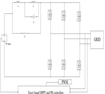
Three phase grid connected CSI shown in Fig .3. The inverter circuit has 6 MOSFET .A dc link inductor is used to connect the double tuned filter and the CSI.
Fig. 3 Three phase grid connected current source inverter
III. SOLAR PV SYSTEM
Solar power generating system operating under principle of photo voltaic effect When the solar radiation fall on the PV cell the electrons in the atoms moves from PV
ARRAY INVERTER
GRID
Fuzzy based MPPT and PR control PV
ARR AY
CHOPP ER
INVERT ER
valence band to conduction band and produce electricity.The PV cell manufacture gives the parameter at STC (Standard Test Condition): an irradiance of 1,000 W/m2 the standard reference spectral irradiance air mass 1.5 and a cell temperature of 25° C. The output voltage and current denoted by the following equation
VOC = VOC,STC × ln 𝐸
ln 1000[ 1+ α(θ – 25) ](1)
ISC = ISC,STC × 𝐸
ln 1000[ 1+ β(θ – 25) ](2)
The maximum current and voltage derive by the following equations
VMPP = VMPP,STC × ln 𝐸
ln 1000[ 1+ α(θ – 25) ] (3)
IMPP = IMPP,STC × 𝐸
ln 1000[ 1+ β(θ – 25) ] (4)
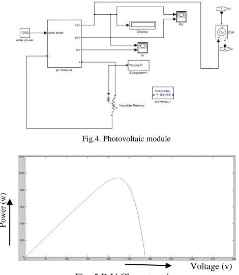
Where ISC is solar cell short circuit current, VOC is solar cell open circuit voltage, VMPP is solar cell voltage at Maximum Power Point, IMPP is solar cell current at Maximum Power Point, E is actual operating irradiation, θ is actual operating temperature , α is temperature coefficient for voltage , β is temperature coefficient for current .Figure 4.Shows the simple design of simulated PV module. One solar cell gives 0.5V. Totally 560 solar cells are connected in series, so the output voltage is approximately 280 V. Figure 5 and 6 shows the P-V and I-V characteristics of photovoltaic module.
Fig.4. Photovoltaic module
Voltage (v) Fig. 5 P-V Characterstics
Voltage (v) Fig. 6 I-V characteristics
IV. FILTER CIRCUIT
The double tuned resonant filter shown in Fig .7. The resonant filter connected to the CSI through a DC-Link inductor. The double tuned resonant filter is tuned when the impedance of C1 and the total impedance of C2, L1, and L2 are equal
ZC1 = ZC2 +ZL1 +ZL1 (5)
ZC1 = ZT (6)
ZT = ZC2 +ZL1+ZL (7) Where ZC1 is impedance of C1, ZC2 is impedance of C2, ZL1 is impedance of L1, ZL2 is impedance of L2.
Fig. 7 Double tuned resonant filter
V. CPWM BASED CSI
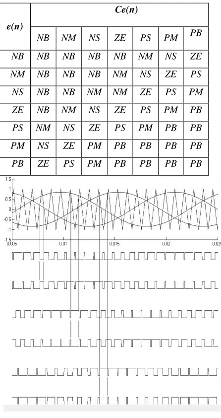
In this method the modulating (reference) signal compared with the high frequency triangular (carrier) signal. Intersection of reference and carrier signal gives the switching instant. The CPWM scheme for switching of CSI shown in Fig.8 . It has one carrier signal and three modulating signal which are having phase shift 120°
P
o
w
er
(
w
)
Cu
rre
n
t
Fig. 8 CPWM scheme for switching of CSI
VI. FUZZY BASEDMPPT AND PR CONTROLLER
A. Fuzzy Logic ControllerBasedMPPT
To extract the maximum power from the solar system MPPT is used.A FLC based MPPT shown in Fig. 9. The MPPT is controlled by the fuzzy logic controller which is suitable for all weather condition. The input of the fuzzy logic controller is given by the following equation
∆P = P (k) – P (k-1) (8)
∆IPV = IPV (k) – IPV (k-1) (9) Where ∆P is output power of PV array, ∆IPV is output current of PV array
The output equation is
∆Ig, ref = Ig, ref (k) – Ig, ref (k-1) (10) Where Ig, ref is grid current reference . The input and output variables are divided into seven fuzzy subset PB (Positive Big), PM (Positive Medium), PS (Positive Small), ZE (Zero), NB (Negative Big), NM (Negative Medium), NS (Negative Small). Therefore the algorithm contains 49 rules. The rules are shown in the table I.
Fig. 9 FLC based MPPT
Table I
FUZZY LOGIC RULES
Fuzzy combination operated by Mamdani’s method. The membership function shown in Fig. 10. Centre Of Area algorithm used for defuzzification.
(a)
(b)
(c)
Fig. 10.Membership function (a) input ∆P (b) input ∆I(c) Output ∆D
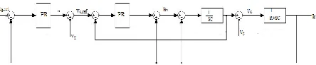
B. PR Control
PR control used in voltage and current loop controllers. The PR controller transfer function is
Y = Kpe(t) + Z(t)
(11 )
The voltage loop and current loop controller is shown in Fig. 11.
e(n)
Ce(n)
NB NM NS ZE PS PM PB
NB NB NB NB NB NM NS ZE
NM NB NB NB NM NS ZE PS
NS NB NB NM NM ZE PS PM
ZE NB NM NS ZE PS PM PB
PS NM NS ZE PS PM PB PB
PM NS ZE PM PB PB PB PB
Fig . 11 .Voltage and current control loop
VI. SIMULATION AND RESULTS
The total output voltage is 220 V. The performance of proposed system simulation is performed in MATLAB/SIMULINK.. The voltage injected to the grid shown in Fig. 12 and the current injected to the grid shown in Fig .14.FFT analysis of Voltage shown in fig.13.and FFT analysis of current shown in fig.15. From FFT analysis Total Harmonics Distortion (THD) in voltage and current is 0.72% and 0.32 % rep.
Fig. 12. Grid Voltage
Fig. 13 FFT plot for voltage injected to the grid
Fig. 14 Grid Current
Fig. 15. FFT plot for current injected to the grid
VII.CONCLUSION
Fuzzy based three phase single stage grid connected PV system has been proposed. The harmonics are eliminated by the double tuned resonant filter. The power extracted from the PV array increased by the fuzzy based MPPT which develop the system performance in varying weather condition. The THD of the grid-injected current was 0.32 % and the THD level of the voltage is 0.72%.
REFERENCES
[1] G.Petrone, G. Spagnuolo, and M. Vitelli, ―A multivariable perturb- and-observe maximum power point tracking technique applied to a single-stage photovoltaic inverter,‖ IEEE Trans. Ind. Electron., vol. 58, no. 1, pp. 76–84, Jan. 2011.
[2] E. Villanueva, P. Correa, J. Rodriguez, and M. Pacas, ―Control of a single- phase cascaded H-bridge multilevel inverter for grid-connected photo- voltaic systems,‖ IEEE Trans. Ind. Electron., vol. 56, no. 11, pp. 4399– 4406, Nov. 2009
[3] N.A.Rahim, K.Chaniago,and J.Selvaraj,―Single-phase seven-level grid- connected inverter for photovoltaic system,‖ IEEE Trans. Ind. Electron., vol. 58, no. 6, pp. 2435–2443, Jun. 2011.
[4] Jia-MinShen, Hurng-LiahngJou,and Jinn-ChangWu, ―Novel Transformerless Grid-Connected Power Converter With Negative Grounding for Photovoltaic Generation System‖ IEEE Trans.
Power Electron., vol. 27, no. 4, pp. 1818–1829, Sep. 2012.
[5] Samuel VasconcelosArajo, Peter Zacharias, and RegineMallwitz, ―Highly Efficient Single-Phase Transformerless Inverters for Grid-Connected Photovoltaic System,‖ IEEE Trans. Ind. Electron., vol. 57, no. 9, pp. 3118–3128, Sep. 2010.
[6] Hiren Patel and VivekAgarwal,― A Single-Stage Single-Phase Transformer-Less Doubly Grounded Grid-Connected PV Interface
‖ IEEE Trans.Energy Conversion vol. 24, no. 1, pp. 93-101
march 2009.
[7] B.Sahan, A.N. Vergara, N. Henze, A. Engler, and P. Zacharias, ―A single –stage PV module integrated converter based on a low-power current-source inverter,‖ IEEE Trans. Ind. Electron., vol. 55, no. 7, pp. 2602–2609, Jul. 2008
[8] P.P.DashandM.Kazerani,―Dynamic
modellingandperformanceanalysis of a grid-connected current-source inverter-based photovoltaic system,‖ IEEE Trans.
Sustainable Energy, vol. 2, no. 4, pp. 443–450, Oct. 2011.
[9] S.Jain and V. Agarwal, ―A single-stage grid connected inverter topology for solar PV systems with maximum power point tracking,‖
IEEE Trans. Power Electron., vol. 22, no. 5, pp. 1928–1940, Sep. 2007.
[10]
[11] Darwish, A. K. Abdelsalam, A. M. Massoud, and S. Ahmed, ―Sin- gle phase grid connected curent source inverter: Mitigation of oscillating power effect on the grid current,‖ in Proc. IET Conf.
Renewable Power Generation, Sep. 2011, pp. 1–7.
[12] R. T. H. Li, H. S.-H. Chung, and T. K. M. Chan, ―An active modulation technique for single-phase grid-connected CSI,‖ IEEE
Trans. Power Elec- tron., vol. 22, no. 4, pp. 1373–1382, Jul. 2007.
[13] K.Hirachi and Y. Tomokuni, ―A novel control strategy on single-phase PWM current source inverter incorporating pulse area modulation,‖ Proc. Power Convers. Conf., vol. 1, pp. 289–294, Aug. 1997.
[14] S.Nonaka, ―A suitable single-phase PWM current source inverter for utility connected residential PV system‖ Sol. Energy Mater. Sol. Cells, vol. 35, pp. 437–444, Sep. 1994.
[15] S.B.Kjaer, J.K.Pedersen, and F.Blaabjerg, ―A review of single-phase grid-connected inverters for photovoltaic modules,‖ IEEE
Trans. Ind. Appl., vol. 41, no. 5, pp. 1292–1306, Sep.–Oct. 2005
[16] . Tsai-Fu, C.Chih-Hao, L. Li-Chiun, and K. Chia-Ling, ―Power loss comparison of single- and two-stage grid-connected photovoltaic sys- tems,‖ IEEE Trans. Energy Convers., vol. 26, no. 2, pp. 707–715, Jun. 2011.
photovoltaic system,‖ IEEE Trans. Power Electron., vol. 26, no. 4, pp. 1022–1030, Apr. 2011.
[18] C.Cecati, F.Ciancetta, and P.Siano,―A multi level inverter for photovoltaic systems with fuzzy logic control,‖ IEEE Trans. Ind.
Electron., vol. 57, no. 12, pp. 4115–4125, Dec. 2010.