ABSTRACT
LEONARD, ALEXANDER J. Implementation of a System-on-Chip for Self-Healing of Analog
Receiver Components in a 65nm CMOS Process. (Under the direction of Paul Franzon.)
For hardware applications which require complex, real-time calibration, it is often useful
to have an integrated microcontroller unit (MCU) as part of a system on-chip (SoC). This
document describes the process of implementing such a system using industry-standard VLSI
design tools for the IBM CMOS 10LPe 65nm technology node. The architecture for the system
includes an ARM Cortex-M0 microcontroller, an AHB-Lite bus, relatively standard SRAM,
and various other peripherals. All standard cells used in the final layout, including the
SRAMs, were produced by Virage (now Synopsys).
In relation to a dedicated hardware design in the form of an application specific
inte-grated circuit (or ASIC), the choice to base the design around an MCU capable of running
instructions compiled directly from C has its advantages. This is especially true considering
the early stage of the intended software at the time. The drawbacks of using a microcontroller
include added complexity, area and power overhead, as well as the time required for proper
implementation.
Implementation of a System-on-Chip for Self-Healing of Analog Receiver Components in a
65nm CMOS Process
by
Alexander J. Leonard
A thesis submitted to the Graduate Faculty of
North Carolina State University
in partial fulfillment of the
requirements for the Degree of
Master of Science
Electrical Engineering
Raleigh, North Carolina
2011
APPROVED BY:
DEDICATION
BIOGRAPHY
Alexander Leonard was born in Burnsville, MN on July 2
nd, 1986 where he attended grade
school until moving to Springfield, VA for high school. In the Fall of 2004 he started his
undergraduate studies at North Carolina State University in Raleigh, and he was awarded a
ACKNOWLEDGEMENTS
I’d like to acknowledge the following people for their invaluable contributions to this work.
•
Meeta Yadav - for her guidance in the early stages of the project before moving on to
greener pastures
•
Ojas Bapat - for his help in working through the design process
•
Thor Thofolfsson - for his help in working through the design process
•
Wallace Harwood - for his guidance and technical expertise
•
Steve Lipa - for his help on just about everything from NDAs to FIB work in the lab
•
Michael Steer, Rhett Davis, and Paul Franzon - for taking the time to serve on my
TABLE OF CONTENTS
List of Tables
. . . .
vii
List of Figures
. . . .
viii
Chapter 1
Introduction
. . . .
1
1.1
Background . . . .
1
1.2
Contribution . . . .
2
1.3
Notable Constraints . . . .
2
1.3.1
Aspect Ratio . . . .
2
1.3.2
Memory . . . .
2
1.3.3
Time . . . .
3
1.4
Outline . . . .
3
Chapter 2
Architecture
. . . .
4
2.1
Slaves . . . .
5
2.1.1
Memory . . . .
6
2.1.2
ADC . . . .
7
2.1.3
Digital Programming Interface . . . .
7
2.1.4
Readback . . . .
9
2.1.5
Healing ASIC . . . .
9
2.2
AHB-Lite Bus . . . .
10
2.3
ARM Core . . . .
12
Chapter 3
Verification
. . . .
14
3.1
Strategy . . . .
15
3.2
Risks . . . .
16
3.3
Risk Mitigation . . . .
16
3.4
Summary . . . .
17
Chapter 4
Implementation
. . . .
18
4.1
Synthesis . . . .
18
4.1.1
Basic Flow . . . .
18
4.1.2
Integrated Approach . . . .
19
4.1.3
Split Approach . . . .
19
4.2
Place and Route . . . .
19
4.2.1
Configuration and Floorplaning . . . .
19
4.2.2
Placement . . . .
21
4.2.3
Clock Tree Synthesis . . . .
23
4.3.2
STA . . . .
25
4.3.3
Importing . . . .
27
4.3.4
DRC . . . .
28
4.3.5
LVS . . . .
28
Chapter 5
Results
. . . .
30
5.1
Manual Debug . . . .
30
5.2
FIB . . . .
31
5.2.1
Alternative . . . .
34
Chapter 6
Conclusion
. . . .
35
6.1
Possible Improvements . . . .
35
6.2
Future Work . . . .
36
References
. . . .
37
Appendices
. . . .
38
Appendix A Logic
. . . .
39
Appendix B Testbenches . . . .
58
B.1 Peripheral RTL . . . .
58
B.2 JTAG . . . .
65
B.2.1
ARM Core . . . .
73
B.2.2
System Level . . . .
79
Appendix C Scripts . . . .
84
C.1 Synthesis . . . .
84
C.1.1 ARM Core . . . .
84
C.1.2 System-level . . . .
112
C.2 Place and Route . . . .
121
LIST OF TABLES
Table 2.1
Abridged List of Files Produced by the Memory Generator . . . .
6
Table 2.2
Encoding for ADC Control Address . . . .
7
Table 2.3
Encoding for Digital Programming Interface Address . . . .
8
Table 2.4
System Memory Map (byte addressable) . . . .
11
Table 2.5
Cortex-M0 Configuration Options . . . .
13
Table 3.1
Tests Performed by Integration Kit Testbench . . . .
15
Table 3.2
Tests Performed Manually for Peripherals . . . .
16
Table 4.1
Static Timing Analyses . . . .
26
Table 4.2
Common DRC Errors . . . .
28
LIST OF FIGURES
Figure 1.1
Feedback Loop for Self-Healing . . . .
2
Figure 2.1
Digital Healing Block . . . .
4
Figure 2.2
GPIO Functionality . . . .
6
Figure 2.3
Waveforms Showing DPI Operation . . . .
7
Figure 2.4
AHB-Lite Components . . . .
10
Figure 2.5
ARM Cortex-M0 Components . . . .
12
Figure 3.1
State of Verification Before Tapeout . . . .
14
Figure 4.1
Empty Floorplan . . . .
20
Figure 4.2
Power Stripes . . . .
20
Figure 4.3
Required Pin Placement . . . .
21
Figure 4.4
Welltap Placement . . . .
22
Figure 4.5
Cell Placement Options . . . .
23
Figure 4.6
Fully Routed Design . . . .
24
Figure 4.7
Clock Domains . . . .
27
Figure 4.8
Virtuoso Layout View . . . .
27
Figure 5.1
Waveforms Driving JTAG Signals . . . .
30
Figure 5.2
Metal Layers Cross-section . . . .
32
Figure 5.3
Routing Layers Barely Visible . . . .
33
Figure 5.4
Mostly Visible Routing Layers . . . .
33
Chapter
1
Introduction
1.1
Background
The need for new frequency bands, smaller antenna sizes, greater data throughput rates, and
faster digital circuitry has driven modern integrated circuit fabrication processes to produce
lower and lower minimum feature sizes. This deep submicron, mostly CMOS, technology is
capable of producing the speed required for millimeter wave telecommunication components,
but also produces wider process variations which can put great pressure on the IC design
process. The DARPA HEALICs program was created to address this issue, and Raytheon was
given the task of developing the techniques necessary for creating mixed-signal SoCs at high
yield which perform well in environments of extreme process variations and aging effects.
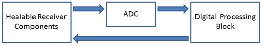
[1]This is accomplished through the creation of self-healing integrated circuits that sense
out-of-spec performance and automatically tune themselves to restore correct functionality based
upon a given healing algorithm.
[2]The performance sensing mechanisms in this project were
Figure 1.1: Feedback Loop for Self-Healing
1.2
Contribution
My goal in this project was to assemble, from hardware description to final layout, the digital
processing block that could make use of the feedback from the ADC to direct a healing
algorithm. The algorithm would also need to be able to directly control the digital tuning
knobs employed throughout the chip. To accomplish this task, I was given access to a host of
industry-standard VLSI design tools as well as the following:
•
Configurable RTL and testbench for an ARM Cortex-M0 microcontroller
•
SRAM generator from Virage Logic
•
Standard cells designed for the IBM 10LPe 65nm CMOS process, also from Virage Logic
•
AHB-Lite bus RTL generator from ARM
•
RTL for SRAM bridges and GPIOs to interface with the AHB-Lite bus, also from ARM
1.3
Notable Constraints
1.3.1
Aspect Ratio
The dimensions which the layout could not exceed were approximately 0.5
mm
by 3
mm
. This
is more than enough space in a 65nm process to fit all the cells that make up the processing
unit. However, the aspect ratio is 6:1 which can constrain routing considerably if the extra
area is packed with memory.
1.3.2
Memory
necessary was unknown. This resulted in trying to fit as much memory as possible into the
space provided.
1.3.3
Time
The most difficult constraint to deal with was the amount of time available before tapeout.
I had very little experience with script-based automation of a digital design flow, and time
would also be required to familiarize myself with the abundance of IP that I had to work
with. The time constraint was dealt with by multitasking as much as possible, keeping the
architecture as simple as possible, and by limiting verification to only what could be properly
verified in a short time span.
1.4
Outline
This thesis is organized as follows.
Chapter 1: Introduction
Chapter 2: Architecture
Provides details regarding the system-level components and organization
Chapter 3: Verification
Describes the verification techniques employed before tapeout
Chapter 4: Implementation
Focuses on the critical steps in the design automation flow
Chapter 5: Results
Reviews the result of my work and the current state of affairs
Chapter 6: Conclusion
Chapter
2
Architecture
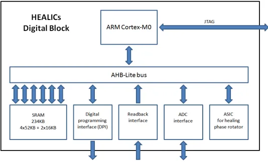
The architecture of the system as shown in Figure 2.1 can be broken into three main
com-ponents: Slaves, Bus Interface, and ARM Core. The ARM core, being the master to the bus,
initiates a read or write request which is directed by the bus to the appropriate slave based
on the address supplied. This is known as memory mapping.
Figure 2.1: Digital Healing Block
2.1
Slaves
According to the project objective and predefined interface with the analog components, the
slaves needed were as follows.
•
SRAM
•
ADC Controller
•
Digital Programming Interface
The role of the slaves and even how they should be implemented was continuously
changed, and the following additional slaves were added late in the process.
•
Readback
•
Healing ASIC
Midway through the process, Wallace Harwood from ARM came to host a training session
regarding the features and suggested implementation strategy of the ARM IP bundle. We
were shown how to use some helpful RTL components that had been so-far undiscovered.
These components are described as follows.
Reset synchronizer
Ensures that the system comes out of reset synchronously given an asynchronous
ex-ternal reset pin, and also ensures that the system stays in reset for more than one clock
cycle
AHB-Lite bus RTL generator
Automatically generates the RTL for an AHB-Lite bus with the specified number of
slave ports
AHB-Lite to SRAM bridge
Provides the logic translation between AHB-Lite protocol signals and standard SRAM
control signals
General Purpose IO
Figure 2.2: GPIO Functionality
2.1.1
Memory
The implementation of the memory was only fully settled late in the process as the number
and size of memory blocks employed depended heavily on the extra space available in the
layout. The early stages of memory design mainly involved becoming familiar with the
mem-ory generator from Virage. The generated files which were required in the design process are
listed in Table 2.1.
Table 2.1: Abridged List of Files Produced by the Memory Generator
File Extension
Purpose
v
Verilog model
lib
Cell library information (timing, load capacitance etc), can be
converted to Synopsys db format
plef
Provides only the information about the layout necessary for
place and route
gds
Provides full layout information for streamout to final gds file
2.1.2
ADC
Access to the ADC was implemented using a single GPIO for easy memory mapping . The
operation of the ADC was designed by Raytheon and implemented by Steve Lipa at NC State.
It was to have an enable line, a reset line, and a 16 bit output. It was basically implemented as
a counter which, if enabled, would count down from a set starting value at a rate determined
by its analog input. It would there for need to be enabled and then disabled in a very precise
amount of time to avoid a false reading. Having to enable and disable it with software and
through a GPIO made uncertain the reaction time of the enable signal. The solution was an
ASIC which could be programmed through the GPIO’s output bits and then left to control
the enable signal directly. The reset control line, however, came directly from the output of
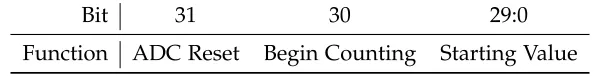
the GPIO. The 16 bit output of the ADC was connected to the GPIO’s external input and read
by the core at the same address. The encoding used for the ADC control address is shown
below.
Table 2.2: Encoding for ADC Control Address
Bit
31
30
29:0
Function
ADC Reset
Begin Counting
Starting Value
2.1.3
Digital Programming Interface
The digital programming interface in the analog circuitry was implemented with shift
regis-ters of varying word lengths which can be thought of as tuning knobs with varying maximum
values. A value is shifted into all of the shift registers simultaneously on positive clock edges
and then latched in to only the one which corresponds to the address given as shown in
Figure 2.3.
that would automatically go through the process of writing a specific number of bits based
on exactly which shift register (or knob) was being programmed. An early RTL version of this
ASIC was produced, but the team at Raytheon later objected to this approach due to concerns
over flexibility. The documentation at the time regarding which shift registers were needed
and even how many bits were used from each one was still being determined. Hard coding
these things was extremely risky. The solution was to connect the DPI control lines directly
to the output of a GPIO. This will result in a slower programming procedure, because a new
word will have to be written to the bus for every bit change on the interface lines (including
the clock line), but this method offloads all of the specifics to the software which is far less
risky. The DPI for the digital block ultimately amounted to a single GPIO with the address
encoding shown below.
Table 2.3: Encoding for Digital Programming Interface Address
Bit
31:10
9
8
7
6:0
2.1.4
Readback
The readback slave was created for verifying that the analog circuitry could be tuned. A
special shifter register was created for an arbitrary tuning address, and its output signals
were fed back into the digital block. A GPIO was used to capture these signals, allowing
them to be read with software.
2.1.5
Healing ASIC
2.2
AHB-Lite Bus
Figure 2.4: AHB-Lite Components
Table 2.4: System Memory Map (byte addressable)
Starting Address
Function
0x00000000
SRAM
0x0003A800
ADC Control
0x0003A804
Invalid
0x0003B000
DPI Control
0x0003B004
Invalid
0x0003B800
Readback
0x0003B804
Invalid
0x0003C000
Healing ASIC
2.3
ARM Core
Figure 2.5: ARM Cortex-M0 Components
Table 2.5: Cortex-M0 Configuration Options
Parameter
Value
Interrupts
32
Endianness
Big-endian
SysTick Timer
Included
Wakeup Interrupt Controller
Included
Architectural Clock Gating
Not Included
Watchpoint Comparators
2
Breakpoint Comparators
4
Debug (Serialwire or JTAG)
JTAG
Chapter
3
Verification
In a large, complex, and mostly automated design flow, verification after each step is crucial.
Given the complexity of the ARM core and the limited time available to integrate it, the
verification process was done in pieces as shown in figure Figure 3.1, and no system-level test
bench was produced before tapeout.
3.1
Strategy
The ARM core was separately verified at the RTL level by the included tests provided in
ARM’s integration kit as outlined in Table 3.1. This integration kit employs a testbench
which instantiates two instances of the core, and all testbench sequences are written in C to
run on one of the instantiated cores in simulation. Some of the C code is meant to be run
on the core instantiation that drives the DUT, and some of the C code is meant to run on the
instantiation of the DUT itself. The configured ARM core RTL was successfully verified in
this way.
Table 3.1: Tests Performed by Integration Kit Testbench
Name
Test
HelloW
Processor CPU ID Value
Reset
1. AHB Fault response from invalid memory region, 2. System
Reset Request pin
Sleep
1. Proper output when the core enters sleep mode, 2. Wakeup
from debug port
Interrupt
1. Non-maskable interrupts, 2. Bring processor out of wait-state
DHRY
Modified version of the Dhrystone 2.1 Benchmark program
Debug
1. Read and write to memory using Word, Halfword and Byte
accesses, 2. Produce hard fault and check LOCKUP signal, 3.
Ex-ternal Debug Request causes the core to enter halting debug, 4.
HALTED output is driven when the core is in halting debug, 5.
Driving the DBGRESTART input produces correct
acknowledge-ment at output
outlined in Table 3.2.
Table 3.2: Tests Performed Manually for Peripherals
Peripheral
Test
Memory
Wrote to boundaries of all 6 blocks to view the active block,
thus ensuring a correct memory map. Also read values
back from blocks in various orders to confirm access
DPI
Drove individual output signals and confirmed correct
en-dianness of address
ADC
Read 16 bit final counter output (fake) and drove signals
to test ADC controller
Readback
Read back 16 bit value (fake)
ASIC
Read default output and changed input once to verify
ex-pected output (non-comprehensive)
3.2
Risks
There are, of course, risks associated with not having a full system-level testbench. Possible
risks include:
1. A faulty connection between the core and the bus
2. Various other pins for the core not being driven or tied correctly
3. Not being able to verify that synthesis has kept the logic intact.
3.3
Risk Mitigation
should then also be named "HRDATA", so that there can be very little room for mistakes
when connecting this wire to the core and to the bus. The second risk was mitigated by
keeping tracking of a list of all core pins which were not directly tied to the bus and not
given system-level pin access. Advice for how to tie each of these pins was procured during
the ARM training session. However, at that time the list was incomplete, so all other pins
were tied low by default. This unfortunately resulted in problems using the debug port as
explained in Chapter 5. The third risk was mitigated by paying close attention to any and all
warnings from the synthesis tool.
3.4
Summary
A summary of all pre-tapeout verification components is provided below.
1. Automated ARM core RTL testbench
2. Manual bus and peripheral RTL testbench
3. Synthesis timing reports
4. Logical equivalence checking
5. Static timing analysis
6. Design rule checking
Chapter
4
Implementation
4.1
Synthesis
4.1.1
Basic Flow
The goal of synthesis is to convert a system’s RTL logic description into a netlist, which
contains only instantiations of standard cells and the nets required to connect them properly.
A simple synthesis flow is outlined as follows.
1. Read all verilog files and specify the top module name
2. Specify all required cell libraries
3. Specify the clock signals and a target period
4. Specify the following other constraints: estimated clock skew, pin delays, driving and
load cells
5. Link the design
6. Compile the design
7. Check for hold violations and recompile the design (hold-fixing)
8. Verify that the required constraints are met
4.1.2
Integrated Approach
The biggest problem that was faced initially was producing a full netlist translation, or one
that did not leave any components as "black boxes". Various parts of the ARM core would
not properly synthesize. Two possible solutions were explored in solving this problem. The
first was to use a more complicated script flow as outlined in a TSMC-based example flow
provided by ARM. These scripts were extremely complicated and incorporated everything
from synthesis, through place and route, and into timing analysis. Stripping this down to
synthesis only was an arduous task that was ultimately driven by systematically eliminating
error messages which were not fully understood. This turned out to be a very poor approach.
A mostly working script was eventually developed, as shown in Listing C.1, but the
system-level black boxing problem never went away.
4.1.3
Split Approach
The second approach was to use the altered script as described above to synthesize the ARM
core’s top module by itself, which was successful when isolated. From this, the core’s
sepa-rate netlist was included with the bus and peripheral RTL for a final round of synthesis. The
script used for this step is shown in Listing C.7. Various other benefits came of this approach
including the fact that scan chains could be inserted into the core only, and the final
synthe-sis compile time was decreased, if only slightly, due to less RTL needing translation. Any
decrease in compile time was useful because the synthesis flow would be re-run many times
to account for continuous changes to the peripherals of the bus.
4.2
Place and Route
The task of layout generation can be broken into 5 major steps which are commonly employed
in any place and route flow. These steps are outlined below in order of execution as well as
in the script which was used for place and route, shown in Listing C.11.
4.2.1
Configuration and Floorplaning
The first step in the configuration process was to setup the following parameters as outlined
below.
•
Target core utilization (placement density)
•
Global power net names
The second key step in the configuration process was to specify the constraints of the
design, such as which metal layers are available for routing. Floorplaning was the last step
before any automated placement could occur. In this step, the exact dimensions available
were specified, and this served to contain the layout to the exact space available on the chip
for the digital block as shown in figure Figure 4.1.
Figure 4.1: Empty Floorplan
Another consideration was planning for power dispersion to the standard cell rails. This
is important, because if too many high-activity cells are isolated from the power supply then
unexpected behavior can occur due to power variations. Disbursing power to the rails is
usually done using the technique of creating power rings around the design, but a different
approach was used for this design in the interest of keeping all vertical space possible for
routing to the memories. As shown in the figure Figure 4.2, stripes were placed through the
design on the top-most metal layer available. These stripes were carefully placed to ensure
orthogonal intersection with all rails, including the rails contained in the memory blocks,
often in more than one location.
The final step was to insert the pins that would be used to interface with the rest of the
chip. All of the pin locations had to be manually specified according to the provided layout
shown in Figure 4.3.
Figure 4.3: Required Pin Placement
4.2.2
Placement
The next key step in any place and route flow is cell placement. This step includes the
placement of the memories, which were added manually for maximum efficiency. The tool is
capable of placing the memories like any other standard cell, but it seemed best to keep the
standard cells together in order to create a better aspect ratio for routing between them.
Figure 4.4: Welltap Placement
(a) placeDesign
(b) amebaPlace
Figure 4.5: Cell Placement Options
4.2.3
Clock Tree Synthesis
Clock tree synthesis is an important step in minimizing clock skew. This step must be done
before routing to give the tool the space it needs for maximum optimization and skew
man-agement. Buffers are automatically added to compensate for differing loads between tree
segments and to add specific delay to help balance skew. Unfortunately, this step cannot be
done before placement because the location of the register cells will determine the optimum
clock tree. This was not a problem, however, given the relatively low placement density of
this particular design. Although the debug clock was predicted to run very slowly, its tree
was also specifically synthesized after the main clock group. This was thought to reduce the
potential for hold violations in the debug domain, which can also be caused by excessive
skew.
4.2.4
Routing
(a)
(b)
Figure 4.6: Fully Routed Design
4.2.5
Output
The final step in the place and route process involves getting the layout ready for final
verifi-cation. Since static timing analysis needs information about the delay added by the routing
process, RC extraction must be completed. The results of this were stored in a file that uses
the standard parasitic exchange format (SPEF) due to the ubiquitousness of that format. The
manufacturing process requires that some layers maintain a certain density throughout the
design, so filler cells must be specifically included to ensure that all design rules are met.
These filler cells can, however, be substituted for decoupling capacitor cells to achieve the
same result with one added benefit. Decoupling capacitors will serve to reduce noise on the
power supply rails caused by intense switching activity. The last step before finalizing place
and route was to go through an automated, post-route optimization process to help reduce
various DRC errors and static timing violations. The final step in the process was to write
the final netlist required for LVS and to stream out the design in Graphic Database System
format, also for its ubiquity, so that it could be imported into the Virtuoso layout view. A
GDS file contains all hierarchical layout information, including text labels, encoded in binary.
4.3
Final Verification
4.3.1
LEC
A logical equivalence check should be done immediately after a layout is produced from
place and route, which will have added buffers during clock tree synthesis and sometimes
even optimize logic as necessary. The goal of LEC is to ensure that the modifications to the
netlist don’t result in any logical change. Verification like this is necessary any time there’s
an alteration to the netlist. There was never any problem in passing this check.
4.3.2
STA
Static timing analysis, like synthesis, was heavily script-based and ran using Synopsys tools.
The common procedure in this regard is to initially start with a template script and then add
or remove commands as necessary. The final script used for static timing analysis is shown
in Listing C.18, and a list of standard procedures found in most STA templates are outlined
as follows.
•
Defining timing libraries
•
Reading in netlist and defining top level
•
Reading parasitic information
•
Defining the clock(s) and specifying the target period
•
Defining launch and load cells
•
Running timing analysis
procedure for correcting most violations was to re-run the entire flow with tighter constraints
in synthesis.
Table 4.1: Static Timing Analyses
Analysis
Description
min delay
This uses only the shortest path for each clock group and checks
for a hold violation.
max delay
This uses only the longest (critical) path for each clock group and
checks for a setup violation.
max capacitance
This checks the amount of capacitance on each routing net.
max fanout
This checks the number of receiving cells for a given driving cell.
max transition
This checks the amount of time a given net will take to transition
between values based on the library information and parasitics
provided.
recovery
This effectively checks for hold violations
removal
This checks the amount of time that a register has to sample
input data after coming out of asynchronous reset if that reset is
controlled on-chip.
Figure 4.7: Clock Domains
4.3.3
Importing
At this point, the resulting layout in GDS form was imported into Virtuoso. The benefit of this
is a full, and much more final view of the layout as shown in figure Figure 4.8. The importing
process requires not only the GDS file, but also a layermap file which is used in translating
the raw GDS layer information to process-specific layer information. Given our current level
of inexperience at the time and the sheer volume of IP that was received from IBM, finding
the correct layermap initially proved difficult. Importing the wrong layermap resulted in
false-positive DRC errors and an incomplete layout view. A support representative from
Virage (now Synopsys), while assisting us in resolving DRC errors related to the memories,
requested our layermap file and found the issues. After a change or addition to various layer
entries, we had a working, although rather concise translation. Later in the process the full
layermap file was found, but there were no changes in results after implementing this new
set of translations.
4.3.4
DRC
A design rule check is always necessary for fabrication of any chip, digital or analog. The
design rules are set (and checked) by the foundry to ensure that any feature outlined in
the layout can be properly fabricated. This design rule check was done with a tool called
Calibre from Mentor Graphics, which would read the layout directly from the viewer in
Virtuoso to perform the check. Initially, due to a slew of false-positives resulting from an
incorrect layermap translation file, the tool found thousands of DRC errors. As it turned
out, there were only a few real design rule violations produced by Encounter that required
manual correction. Luckily the amount of DRC errors requiring manual correction was never
prohibitive. Some of these errors are listed in Table 4.2 along with the solution employed in
resolving the violations.
Table 4.2: Common DRC Errors
Violation
Solution
Minimum vertex
Corrected easily by filling the vertex with the appropriate metal
Minimum spacing
This error can be difficult to correct for with heavy routing
con-gestion. The solution was usually to re-run the flow starting at
place and route and insert a placement block to ensure that some
other routing behavior was employed at the location in question.
Well spacing
Corrected easily by manually filling the gap
ESD
Manually insert antenna diode at the location in question
4.3.5
LVS
Chapter
5
Results
The original strategy for programming the memory on the chip was to use a standard
de-bugger and accompanying software to access the bus directly from the ARM core’s debug
port. After hours of attempting to work through varying failure messages from the debugger
software, the appropriate support staff was contacted who then indicated that our system
design was not compatible with their debugger due to lack of flash-based memory. We had
previously been assured by ARM support staff that the JTAG debug port was capable of
accessing the bus, so a manual approach was taken to provide debug functionality.
5.1
Manual Debug
While the Raytheon debug team set up a makeshift logic analyzer with LabView, I was tasked
with creating the system-level testbench that would be required to work out exactly how to
access the bus through the debug port. ARM’s integration kit testbench came with JTAG
driving routines, written in C, which served as a model for the inputs required to perform
various debug routines. These routines, translated to verilog, are shown in Listing B.2. The
LabView-based logic analyzer created at Raytheon was made to replicate input waveforms
produced by a verilog simulation as shown in Figure 5.1.
We were, however, still unsuccessful in doing any kind of read or write to memory in
simulation or in hardware. By comparing the waveforms produced directly from the
inte-gration kit’s debug test, outlined in Table 3.1, with those from my own testbench, shown
in Listing B.3, it was determined that a certain debugging acknowledgement signal
(CDBGP-WRUPACK) had to go high at a certain point in order to gain JTAG debug access. A successful
read and write from the ARM core’s bus output was simulated with this debug acknowledge
signal tied high. Unfortunately this signal was tied low in our system-level implementation
of the ARM core, so debug access would be impossible with the chips as they were.
5.2
FIB
Focused Ion Beam technology is capable of clearing away material, silicon or otherwise, as
well as adding conductive material to create vias and other structures. As the chips were
physically unable to allow debug access, it was determined that altering the chips using a
FIB would be worth the cost of producing a few working chips. The steps necessary to
prepare for a FIB alteration were as follows.
1. Starting at the RTL level, find a few registers in the path of the debug acknowledge
signal that can be altered in order to effectively tie that signal high.
2. Find the output nets of these registers in the system-level netlist and, through
simula-tion, verify that an alteration can produce successful debug access from the JTAG port.
This was done with the testbench shown in Listing B.4.
3. Find the same nets in the layout and choose to alter the one that seems easiest.
The net that seemed easiest to alter was n496 in u_cortexm0integrationimp.u_cortexm0integration.
A cut would be made to disconnect it from the buffer
u_cortexm0integrationimp.u_cor-texm0integration.U680, and a via would be made to attach the net to the VDD rail that
it conveniently crossed. This was simulated by removing it from the output pin of
u_cor-texm0integrationimp.u_cortexm0integration.U680 and inserting it into the output of a new
tie-high cell (STN_TIE1_1).
Figure 5.2: Metal Layers Cross-section
(a)
(b)
Figure 5.3: Routing Layers Barely Visible
At this stage, it would be very easy to accidentally cut through one of the small nets, so
extra caution was taken to only cut through the areas where no nets were currently exposed.
The task at this point was to clear away as much of the remaining top cover as possible and
to determine which nets in the layout were currently visible. This can be a very difficult task
due to partial visibility as well as the lack of depth information for each net. It’s possible that
all 5 metal layers employed in the routing process would be visible at the same time.
(a) Physical View
(b) Possible Matching Layout View
5.2.1
Alternative
There was only one alterative to physically altering the chips which relied on the scan chains
that were implemented in the ARM core during synthesis. It was thought that the registers
controlling the AHB-Lite bus at the master port should be included in a scan path. By
scanning in a vector that contained the desired control bits in the correct vector positions, it
might be possible to control these pins directly.
Chapter
6
Conclusion
This thesis has described the implementation of an MCU-based SoC for the 65nm technology
node using a modern and heavily script-based VLSI design flow. This was accomplished
using various, pre-designed intellectual properties and the IBM CMOS10LPe fabrication
pro-cess.
Table 6.1: Final Design Metrics
Total Area
Std. Cell Density
Total Memory
1.5
mm
276.5%
234
KB
Estimated Power Consumption
Minimum Clock Period
Time to Implement
94.47
mW
14
ns
~3
months
6.1
Possible Improvements
For example, static timing analysis could have been limited to only a simple setup and hold
check.
6.2
Future Work
REFERENCES
[1] G. Sollner, J. Smolko, S. Lardizabal, R. Molfino, M. Morton, A. Kopa, C. Wang, A. Imhoff,
E. Wyers, A. Leonard, S. Lipa, C. T. Kelley, P. Franzon, M. Steer, J. Bardin, F. Bohn, H.
Wang, K. Dasgupta, and A. Hajimiri, "Tunable Receiver for 6–18 GHz with Autonomous
Self-Healing," Proc. Government Microcircuit Applications and Critical Technology
Con-ference (GOMACTech), pp. 49–52, March 2011.
Appendix
A
Logic
Mem52KB wrapper mem3 Mem13KB wrapper mem5 Mem13KB wrapper mem4 Mem52KB wrapper mem1 Mem52KB wrapper mem2 Mem52KB wrapper mem0 52KB SRAM Bridge slave3 52KB SRAM Bridge slave1 52KB SRAM Bridge slave2 52KB SRAM Bridge slave0 13KB SRAM Bridge slave4 13KB SRAM Bridge slave5 General Purpose IO slave7 General Purpose IO slave6 General Purpose IO slave8 General Purpose IO slave9 Phase Rotator Healing ASIC u_asic ADC Controller u_adc ARM Core u_cortexm0integrationimp AHB-Lite Bus uBusMatrixFigure A.1: Top-level Block Diagram
(clock gate and reset controller not shown, see Listing A.2)
Listing A.1: digitalIntegration.v – Top-level Module
/ / Author : A l e x a n d e r L e o n a r d / / Top−l e v e l s y s t e m module
module d i g i t a l I n t e g r a t i o n (
i np ut wire anTRST , / / c o m e s f r o m p i n i np ut wire TDI , / / c o m e s f r o m p i n output wire TDO, / / g o e s t o p i n output wire nTDOEN, / / g o e s t o p i n output wire LOCKUP, / / g o e s t o p i n i np ut wire SWCLKTCK, / / c o m e s f r o m p i n i np ut wire SWDITMS, / / c o m e s f r o m p i n output wire SISO0 ,
i np ut wire ADC_DATA14, i np ut wire ADC_DATA15, output wire ADDI6 , output wire ADDI5 , output wire ADDI4 , output wire ADDI3 , output wire ADDI2 , output wire ADDI1 , output wire ADDI0 , output wire LE , output wire DPI_CLK , output wire DIN ) ;
‘ i n c l u d e "/mnt/ a r t e m i s / S y n t h e s i s _ V i r a g e / l o g i c a l /cortexm0_ahb/ v e r i l o g /wires . v " / / t o AHB f r o m m a s t e r
wire [ 3 1 : 0 ] HADDR; wire [ 2 : 0 ] HBURST ; wire HMASTLOCK; wire [ 3 : 0 ] HPROT; wire [ 2 : 0 ] HSIZE ; wire [ 1 : 0 ] HTRANS; wire [ 3 1 : 0 ] HWDATA; wire HWRITE ;
wire SYSRESETREQ ; / / t o r e s e t s y n c f r o m c o r e wire [ 3 : 0 ] REMAP;
‘ i n c l u d e "/mnt/ a r t e m i s / S y n t h e s i s _ V i r a g e / l o g i c a l /cortexm0_ahb/ v e r i l o g / i n s t a n c e s . v " CORTEXM0INTEGRATIONIMPNCSU
u _ c o r t e x m 0 i n t e g r a t i o n i m p (
. FCLK (FCLK) ,
. SCLK ( gatedFCLK ) ,
.HCLK ( gatedFCLK ) ,
.DCLK ( gatedFCLK ) ,
. PORESETn ( PORESETn ) ,
. DBGRESETn (DBGRESETn) ,
. HRESETn ( HRESETn ) ,
.SWCLKTCK (SWCLKTCK) ,
. nTRST ( nTRST ) ,
.HADDR (HADDR[ 3 1 : 0 ] ) ,
. HBURST (HBURST [ 2 : 0 ] ) ,
.HMASTLOCK (HMASTLOCK) ,
.HPROT (HPROT [ 3 : 0 ] ) ,
.HREADY (HREADY) ,
. HRESP (HRESP) ,
.HMASTER (HMASTER) ,
.CODENSEQ (CODENSEQ) ,
.CODEHINTDE (CODEHINTDE [ 2 : 0 ] ) ,
. SPECHTRANS (SPECHTRANS) ,
. SWDITMS (SWDITMS) ,
. TDI ( TDI ) ,
.SWDO (SWDO) ,
.SWDOEN (SWDOEN) ,
.TDO (TDO) ,
.nTDOEN (nTDOEN) ,
. DBGRESTART (DBGRESTART) ,
. DBGRESTARTED (DBGRESTARTED) ,
.EDBGRQ (EDBGRQ) ,
.HALTED (HALTED) ,
.NMI (NMI) ,
. IRQ ( IRQ [ 3 1 : 0 ] ) ,
. TXEV (TXEV) ,
. RXEV (RXEV) ,
.LOCKUP (LOCKUP) ,
. SYSRESETREQ ( SYSRESETREQ ) , . STCALIB ( STCALIB [ 2 5 : 0 ] ) ,
. STCLKEN (STCLKEN) ,
. IRQLATENCY (IRQLATENCY [ 7 : 0 ] ) , .ECOREVNUM (ECOREVNUM[ 2 7 : 0 ] ) ,
.GATEHCLK (GATEHCLK) ,
. SLEEPING ( SLEEPING ) ,
. SLEEPDEEP ( SLEEPDEEP ) ,
.WAKEUP (WAKEUP) ,
. WICSENSE (WICSENSE [ 3 3 : 0 ] ) , . SLEEPHOLDREQn (SLEEPHOLDREQn) , . SLEEPHOLDACKn (SLEEPHOLDACKn) ,
.WICENREQ (WICENREQ) ,
.WICENACK (WICENACK) ,
.CDBGPWRUPREQ (CDBGPWRUPREQ) , .CDBGPWRUPACK (CDBGPWRUPACK) ,
. SE ( SE ) ,
. RSTBYPASS ( RSTBYPASS ) ,
. SYSRETAINn ( SYSRETAINn ) , . SYSISOLATEn ( SYSISOLATEn ) ,
.SYSPWRDOWN (SYSPWRDOWN) ,
. DBGISOLATEn ( DBGISOLATEn ) ,
.DBGPWRDOWN (DBGPWRDOWN) ,
. S I 0 ( S I 0 ) ,
. S I 1 ( S I 1 ) ,
. S I 2 ( S I 2 ) ,
. SO0 ( SO0 ) ,
. SO1 ( SO1 ) ,
. SO2 ( SO2 ) ,
endmodule
Listing A.2: instances.v
/ / Author : A l e x a n d e r L e o n a r d / / f o r u s e i n i n t e g r a t i o n
/ / t i e o f f c o r e i n p u t s
a s s i g n IRQ [ 3 1 : 0 ] = 3 2 ’ d0 ; a s s i g n DBGRESTART = 1 ’ b0 ; a s s i g n NMI = IRQ [ 0 ] ; a s s i g n RXEV = 1 ’ b0 ;
a s s i g n STCALIB [ 2 5 : 0 ] = { 1 ’ b1 , { 2 5 { 1 ’ b0 } } } ; a s s i g n STCLKEN = 1 ’ b0 ;
a s s i g n IRQLATENCY[ 7 : 0 ] = { 8 { 1 ’ b0 } } ;
a s s i g n ECOREVNUM[ 2 7 : 0 ] = { 2 8 { 1 ’ b0 } } ; / / [ 2 7 : 2 0 ] t o DAP, [ 1 9 : 0 ] t o c o r e a s s i g n SLEEPHOLDREQn = 1 ’ b1 ;
a s s i g n WICENREQ = 1 ’ b0 ;
a s s i g n SCANENABLE = 0 ; / / Scan T e s t Mode E n a b l e a s s i g n SE = SE3 ;
a s s i g n S I 0 = SE0 ; a s s i g n S I 1 = SE1 ; a s s i g n S I 2 = SE2 ; a s s i g n SISO0 = SO0 ; a s s i g n SISO1 = SO1 ; a s s i g n SISO2 = SO2 ; /∗ i np ut b u f f e r s STN_BUF_16 d e l a y s by . 1 5 STN_DEL_L4_1 d e l a y s by . 4 3 ∗/
/ / STN_DEL_L4_1 uSI1 ( . X( S I 1 ) , . A( SE1 ) ) ;
/ / STN_DEL_L4_1 uEDBGRQ ( . X( delayedEDBGRQ ) , . A(EDBGRQ) ) ;
/ / c l o c k g a t i n g
STN_CKGTPLT_1 uClkGate ( . SE ( SE ) ,
.CK(FCLK) , .Q( gatedFCLK ) , .EN( SISO3 ) ) ;
/ / r e s e t s
c o r t e x m 0 _ r s t _ c t l u Re s et s ( / / i n p u t s
.DCLK( gatedFCLK ) , / / Debug c l o c k ( c o n n e c t t o DCLK o f CORTEXM0INTEGRATION) . SYSRESETREQ ( SYSRESETREQ ) , / / S y n c h r o n o u s ( t o HCLK) r e q u e s t f o r HRESETn f r o m s y s t e m . RSTBYPASS ( RSTBYPASS ) , / / R e s e t s y n c h r o n i s e r b y p a s s ( f o r DFT)
/ / o u t p u t s
. PORESETn ( PORESETn ) , / / C o n n e c t t o PORESETn o f CORTEXM0INTEGRATION . HRESETn ( HRESETn ) , / / C o n n e c t t o HRESETn o f CORTEXM0INTEGRATION . DBGRESETn(DBGRESETn) , / / C o n n e c t t o DBGRESETn o f CORTEXM0INTEGRATION . HRESETREQ(HRESETREQ)
) ;
/ / m e m o r i e s
Mem52KB_wrapper mem0 ( .Q( ramrd0 [ 3 1 : 0 ] ) , .ADR( ramad0 [ 1 3 : 0 ] ) , .D( ramwd0 [ 3 1 : 0 ] ) ,
.WE( | { ramwe0 [ 3 : 0 ] } ) , .ME( ramcs0 ) ,
. CLK( gatedFCLK ) ,
.WEM( { { 8 { ramwe0 [ 3 ] } } , { 8 { ramwe0 [ 2 ] } } , { 8 { ramwe0 [ 1 ] } } , { 8 { ramwe0 [ 0 ] } } } ) ) ;
Mem52KB_wrapper mem1 ( .Q( ramrd1 [ 3 1 : 0 ] ) , .ADR( ramad1 [ 1 3 : 0 ] ) , .D( ramwd1 [ 3 1 : 0 ] ) ,
.WE( | { ramwe1 [ 3 : 0 ] } ) , .ME( ramcs1 ) ,
. CLK( gatedFCLK ) ,
.WEM( { { 8 { ramwe1 [ 3 ] } } , { 8 { ramwe1 [ 2 ] } } , { 8 { ramwe1 [ 1 ] } } , { 8 { ramwe1 [ 1 ] } } } ) ) ;
Mem52KB_wrapper mem2 ( .Q( ramrd2 [ 3 1 : 0 ] ) , .ADR( ramad2 [ 1 3 : 0 ] ) , .D( ramwd2 [ 3 1 : 0 ] ) ,
.WE( | { ramwe2 [ 3 : 0 ] } ) , .ME( ramcs2 ) ,
. CLK( gatedFCLK ) ,
.WEM( { { 8 { ramwe2 [ 3 ] } } , { 8 { ramwe2 [ 2 ] } } , { 8 { ramwe2 [ 1 ] } } , { 8 { ramwe2 [ 2 ] } } } ) ) ;
Mem52KB_wrapper mem3 ( .Q( ramrd3 [ 3 1 : 0 ] ) , .ADR( ramad3 [ 1 3 : 0 ] ) , .D( ramwd3 [ 3 1 : 0 ] ) ,
.WE( | { ramwe3 [ 3 : 0 ] } ) , .ME( ramcs3 ) ,
. CLK( gatedFCLK ) ,
.WEM( { { 8 { ramwe3 [ 3 ] } } , { 8 { ramwe3 [ 2 ] } } , { 8 { ramwe3 [ 1 ] } } , { 8 { ramwe3 [ 3 ] } } } ) ) ;
.ADR( ramad4 [ 1 1 : 0 ] ) , .D( ramwd4 [ 3 1 : 0 ] ) ,
.WE( | { ramwe4 [ 3 : 0 ] } ) , .ME( ramcs4 ) ,
. CLK( gatedFCLK ) ,
.WEM( { { 8 { ramwe4 [ 3 ] } } , { 8 { ramwe4 [ 2 ] } } , { 8 { ramwe4 [ 1 ] } } , { 8 { ramwe4 [ 3 ] } } } ) ) ;
Mem13KB_wrapper mem5 ( .Q( ramrd5 [ 3 1 : 0 ] ) , .ADR( ramad5 [ 1 1 : 0 ] ) , .D( ramwd5 [ 3 1 : 0 ] ) ,
.WE( | { ramwe5 [ 3 : 0 ] } ) , .ME( ramcs5 ) ,
. CLK( gatedFCLK ) ,
.WEM( { { 8 { ramwe5 [ 3 ] } } , { 8 { ramwe5 [ 2 ] } } , { 8 { ramwe5 [ 1 ] } } , { 8 { ramwe5 [ 3 ] } } } ) ) ;
cm0ik_ahb_sram_bridge_52KB s l a v e 0
(/ / AHB INTERFACE−−−−−−−−−−−−−−−−−−−−−−−−−−−−−−−−−−−−−−−−−−−− .HCLK( gatedFCLK ) ,
. HRESETn ( HRESETn ) , . HSEL( h s e l 0 ) ,
.HADDR( { haddr0 [ 3 1 : 1 0 ] − 2 2 ’ h0 , haddr0 [ 9 : 0 ] } ) , . HWRITE( hwr ite0 ) ,
. HSIZE ( h s i z e 0 [ 2 : 0 ] ) , . HBURST( h b u r s t 0 [ 2 : 0 ] ) , .HPROT( hprot0 [ 3 : 0 ] ) , .HTRANS( h t r a n s 0 [ 1 : 0 ] ) , .HMASTLOCK( hmastlock0 ) , .HREADY( hreadymux0 ) , .HWDATA( hwdata0 [ 3 1 : 0 ] ) , .HREADYOUT( hready0 ) , . HRESP( hresp0 ) ,
.HRDATA( hrdata0 [ 3 1 : 0 ] ) ,
/ / EMBEDDED SRAM INTERFACE−−−−−−−−−−−−−−−−−−−−−−−−−−−−−−−−−− .RAMRD( ramrd0 [ 3 1 : 0 ] ) , / / Read Data Bus
.RAMAD( ramad0 [ 1 3 : 0 ] ) , / / A d d r e s s Bus
.RAMWD( ramwd0 [ 3 1 : 0 ] ) , / / W r i t e Data Bus .RAMCS( ramcs0 ) , / / Chip S e l e c t
.RAMWE( ramwe0 [ 3 : 0 ] ) / / W r i t e E n a b l e ) ;
cm0ik_ahb_sram_bridge_52KB s l a v e 1
(/ / AHB INTERFACE−−−−−−−−−−−−−−−−−−−−−−−−−−−−−−−−−−−−−−−−−−−− .HCLK( gatedFCLK ) ,
. HBURST( h b u r s t 1 [ 2 : 0 ] ) , .HPROT( hprot1 [ 3 : 0 ] ) , .HTRANS( h t r a n s 1 [ 1 : 0 ] ) , .HMASTLOCK( hmastlock1 ) , .HREADY( hreadymux1 ) , .HWDATA( hwdata1 [ 3 1 : 0 ] ) , .HREADYOUT( hready1 ) , . HRESP( hresp1 ) ,
.HRDATA( hrdata1 [ 3 1 : 0 ] ) ,
/ / EMBEDDED SRAM INTERFACE−−−−−−−−−−−−−−−−−−−−−−−−−−−−−−−−−− .RAMRD( ramrd1 [ 3 1 : 0 ] ) , / / Read Data Bus
.RAMAD( ramad1 [ 1 3 : 0 ] ) , / / A d d r e s s Bus
.RAMWD( ramwd1 [ 3 1 : 0 ] ) , / / W r i t e Data Bus .RAMCS( ramcs1 ) , / / Chip S e l e c t
.RAMWE( ramwe1 [ 3 : 0 ] ) / / W r i t e E n a b l e ) ;
cm0ik_ahb_sram_bridge_52KB s l a v e 2
(/ / AHB INTERFACE−−−−−−−−−−−−−−−−−−−−−−−−−−−−−−−−−−−−−−−−−−−− .HCLK( gatedFCLK ) ,
. HRESETn ( HRESETn ) , . HSEL( h s e l 2 ) ,
.HADDR( { haddr2 [ 3 1 : 1 0 ] − 2 2 ’ h68 , haddr2 [ 9 : 0 ] } ) , . HWRITE( hwr ite2 ) ,
. HSIZE ( h s i z e 2 [ 2 : 0 ] ) , . HBURST( h b u r s t 2 [ 2 : 0 ] ) , .HPROT( hprot2 [ 3 : 0 ] ) , .HTRANS( h t r a n s 2 [ 1 : 0 ] ) , .HMASTLOCK( hmastlock2 ) , .HREADY( hreadymux2 ) , .HWDATA( hwdata2 [ 3 1 : 0 ] ) , .HREADYOUT( hready2 ) , . HRESP( hresp2 ) ,
.HRDATA( hrdata2 [ 3 1 : 0 ] ) ,
/ / EMBEDDED SRAM INTERFACE−−−−−−−−−−−−−−−−−−−−−−−−−−−−−−−−−− .RAMRD( ramrd2 [ 3 1 : 0 ] ) , / / Read Data Bus
.RAMAD( ramad2 [ 1 3 : 0 ] ) , / / A d d r e s s Bus
.RAMWD( ramwd2 [ 3 1 : 0 ] ) , / / W r i t e Data Bus .RAMCS( ramcs2 ) , / / Chip S e l e c t
.RAMWE( ramwe2 [ 3 : 0 ] ) / / W r i t e E n a b l e ) ;
cm0ik_ahb_sram_bridge_52KB s l a v e 3
(/ / AHB INTERFACE−−−−−−−−−−−−−−−−−−−−−−−−−−−−−−−−−−−−−−−−−−−− .HCLK( gatedFCLK ) ,
. HRESETn ( HRESETn ) , . HSEL( h s e l 3 ) ,
.HADDR( { haddr3 [ 3 1 : 1 0 ] − 2 2 ’ h9c , haddr3 [ 9 : 0 ] } ) , . HWRITE( hwr ite3 ) ,
. HBURST( h b u r s t 3 [ 2 : 0 ] ) , .HPROT( hprot3 [ 3 : 0 ] ) , .HTRANS( h t r a n s 3 [ 1 : 0 ] ) , .HMASTLOCK( hmastlock3 ) , .HREADY( hreadymux3 ) , .HWDATA( hwdata3 [ 3 1 : 0 ] ) , .HREADYOUT( hready3 ) , . HRESP( hresp3 ) ,
.HRDATA( hrdata3 [ 3 1 : 0 ] ) ,
/ / EMBEDDED SRAM INTERFACE−−−−−−−−−−−−−−−−−−−−−−−−−−−−−−−−−− .RAMRD( ramrd3 [ 3 1 : 0 ] ) , / / Read Data Bus
.RAMAD( ramad3 [ 1 3 : 0 ] ) , / / A d d r e s s Bus
.RAMWD( ramwd3 [ 3 1 : 0 ] ) , / / W r i t e Data Bus .RAMCS( ramcs3 ) , / / Chip S e l e c t
.RAMWE( ramwe3 [ 3 : 0 ] ) / / W r i t e E n a b l e ) ;
cm0ik_ahb_sram_bridge_13KB s l a v e 4
(/ / AHB INTERFACE−−−−−−−−−−−−−−−−−−−−−−−−−−−−−−−−−−−−−−−−−−−− .HCLK( gatedFCLK ) ,
. HRESETn ( HRESETn ) , . HSEL( h s e l 4 ) ,
.HADDR( { haddr4 [ 3 1 : 1 0 ] − 2 2 ’ hd0 , haddr4 [ 9 : 0 ] } ) , . HWRITE( hwr ite4 ) ,
. HSIZE ( h s i z e 4 [ 2 : 0 ] ) , . HBURST( h b u r s t 4 [ 2 : 0 ] ) , .HPROT( hprot4 [ 3 : 0 ] ) , .HTRANS( h t r a n s 4 [ 1 : 0 ] ) , .HMASTLOCK( hmastlock4 ) , .HREADY( hreadymux4 ) , .HWDATA( hwdata4 [ 3 1 : 0 ] ) , .HREADYOUT( hready4 ) , . HRESP( hresp4 ) ,
.HRDATA( hrdata4 [ 3 1 : 0 ] ) ,
/ / EMBEDDED SRAM INTERFACE−−−−−−−−−−−−−−−−−−−−−−−−−−−−−−−−−− .RAMRD( ramrd4 [ 3 1 : 0 ] ) , / / Read Data Bus
.RAMAD( ramad4 [ 1 1 : 0 ] ) , / / A d d r e s s Bus
.RAMWD( ramwd4 [ 3 1 : 0 ] ) , / / W r i t e Data Bus .RAMCS( ramcs4 ) , / / Chip S e l e c t
.RAMWE( ramwe4 [ 3 : 0 ] ) / / W r i t e E n a b l e ) ;
cm0ik_ahb_sram_bridge_13KB s l a v e 5
(/ / AHB INTERFACE−−−−−−−−−−−−−−−−−−−−−−−−−−−−−−−−−−−−−−−−−−−− .HCLK( gatedFCLK ) ,
. HSIZE ( h s i z e 5 [ 2 : 0 ] ) , . HBURST( h b u r s t 5 [ 2 : 0 ] ) , .HPROT( hprot5 [ 3 : 0 ] ) , .HTRANS( h t r a n s 5 [ 1 : 0 ] ) , .HMASTLOCK( hmastlock5 ) , .HREADY( hreadymux5 ) , .HWDATA( hwdata5 [ 3 1 : 0 ] ) , .HREADYOUT( hready5 ) , . HRESP( hresp5 ) ,
.HRDATA( hrdata5 [ 3 1 : 0 ] ) ,
/ / EMBEDDED SRAM INTERFACE−−−−−−−−−−−−−−−−−−−−−−−−−−−−−−−−−− .RAMRD( ramrd5 [ 3 1 : 0 ] ) , / / Read Data Bus
.RAMAD( ramad5 [ 1 1 : 0 ] ) , / / A d d r e s s Bus
.RAMWD( ramwd5 [ 3 1 : 0 ] ) , / / W r i t e Data Bus .RAMCS( ramcs5 ) , / / Chip S e l e c t
.RAMWE( ramwe5 [ 3 : 0 ] ) / / W r i t e E n a b l e ) ;
cm0ik_gpio s l a v e 6 ( .HCLK( gatedFCLK ) , . HRESETn ( HRESETn ) ,
. HSEL( h s e l 6 ) ,
.HADDR( haddr6 [ 1 0 : 0 ] ) , . HWRITE( hwr ite6 ) , . HSIZE ( h s i z e 6 [ 2 : 0 ] ) , .HTRANS( h t r a n s 6 [ 1 : 0 ] ) , .HREADY( hreadymux6 ) , .HWDATA( hwdata6 [ 3 1 : 0 ] ) , .HREADYOUT( hready6 ) , . HRESP( hresp6 ) ,
.HRDATA( hrdata6 [ 3 1 : 0 ] ) ,
. GPIOIN ( { ADC_EN, 1 5 ’ b0 , ADC_DATA15, ADC_DATA14, ADC_DATA13, ADC_DATA12, ADC_DATA11, ADC_DATA10, ADC_DATA9, ADC_DATA8, ADC_DATA7, ADC_DATA6, ADC_DATA5, ADC_DATA4, ADC_DATA3, ADC_DATA2, ADC_DATA1, ADC_DATA0} ) ,
. GPIOOUT ( { ADC_RST, adc_gpio_data [ 3 0 : 0 ] } ) , / / Output t o IO pad . GPIOEN ( ) , / / Output e n a b l e f o r IO pad
. GPIOINT ( ) ) ;
/ / t h e o u t p u t o f t h i s GPIO d i r e c t l y c o n t r o l s t h e DPI l i n e s a s r e q u e s t e d by R a y t h e o n cm0ik_gpio s l a v e 7 (
.HCLK( gatedFCLK ) , . HRESETn ( HRESETn ) ,
. HSEL( h s e l 7 ) ,
. HRESP( hresp7 ) ,
.HRDATA( hrdata7 [ 3 1 : 0 ] ) , . GPIOIN ( 3 2 ’ b0 ) ,
. GPIOOUT( dpi_gpio_data [ 3 1 : 0 ] ) , / / Output t o IO pad . GPIOEN ( ) , / / Output e n a b l e f o r IO pad
. GPIOINT ( ) ) ;
a s s i g n DPI_CLK = dpi_gpio_data [ 9 ] ; a s s i g n DIN = dpi_gpio_data [ 8 ] ; a s s i g n LE = dpi_gpio_data [ 7 ] ;
a s s i g n { ADDI6 , ADDI5 , ADDI4 , ADDI3 , ADDI2 , ADDI1 , ADDI0 } = dpi_gpio_data [ 6 : 0 ] ; / / r e a d b a c k i n t e r f a c e f o r t e s t i n g DPI a s r e q u e s t e d by R a y t h e o n
cm0ik_gpio s l a v e 8 ( .HCLK( gatedFCLK ) , . HRESETn ( HRESETn ) ,
. HSEL( h s e l 8 ) ,
.HADDR( haddr8 [ 1 0 : 0 ] ) , . HWRITE( hwr ite8 ) , . HSIZE ( h s i z e 8 [ 2 : 0 ] ) , .HTRANS( h t r a n s 8 [ 1 : 0 ] ) , .HREADY( hreadymux8 ) , .HWDATA( hwdata8 [ 3 1 : 0 ] ) , .HREADYOUT( hready8 ) , . HRESP( hresp8 ) ,
.HRDATA( hrdata8 [ 3 1 : 0 ] ) ,
. GPIOIN ( { 1 6 ’ d0 , RB15 , RB14 , RB13 , RB12 , RB11 , RB10 , RB9 , RB8 , RB7 , RB6 , RB5 , RB4 , RB3 , RB2 , RB1 , RB0 } ) ,
. GPIOOUT ( ) , / / Output t o IO pad
. GPIOEN ( ) , / / Output e n a b l e f o r IO pad . GPIOINT ( )
) ;
cm0ik_gpio s l a v e 9 ( .HCLK( gatedFCLK ) , . HRESETn ( HRESETn ) ,
. HSEL( h s e l 9 ) ,
.HADDR( haddr9 [ 1 0 : 0 ] ) , . HWRITE( hwr ite9 ) , . HSIZE ( h s i z e 9 [ 2 : 0 ] ) , .HTRANS( h t r a n s 9 [ 1 : 0 ] ) , .HREADY( hreadymux9 ) , .HWDATA( hwdata9 [ 3 1 : 0 ] ) , .HREADYOUT( hready9 ) , . HRESP( hresp9 ) ,
.HRDATA( hrdata9 [ 3 1 : 0 ] ) ,
. GPIOIN ( a s i c _ g p i o _ d a t a _ i [ 3 1 : 0 ] ) ,
/ / f r o m O j a s B a p a t PR_HEAL u _ a s i c (
. c l o c k ( gatedFCLK ) , . r e s e t ( HRESETn ) ,
. g p i o _ d a t a _ i ( a s i c _ g p i o _ d a t a _ i [ 3 1 : 0 ] ) , . gpio_data_o ( a s i c _ g p i o _ d a t a _ o [ 3 1 : 0 ] ) ) ;
arm_adc u_adc (
. Clock ( gatedFCLK ) ,
. R e s e t (~HRESETn ) , / / R e s e t f o r t h e s y s t e m . from_gpio ( adc_gpio_data [ 3 0 : 0 ] ) ,
.ADC_EN(ADC_EN) ) ;
BP010_a2bm_BusMatrix1x10f32d32a0u uBusMatrix ( / / Common AHB s i g n a l s
.HCLK( gatedFCLK ) , . HRESETn ( HRESETn ) ,
/ / System A d d r e s s Remap c o n t r o l .REMAP(REMAP[ 3 : 0 ] ) ,
/ / I n p u t p o r t S I 0 ( i n p u t s f r o m m a s t e r 0 ) . HADDRSI0(HADDR[ 3 1 : 0 ] ) ,
. HTRANSSI0 (HTRANS [ 1 : 0 ] ) , . HWRITESI0 (HWRITE) , . HSIZESI0 ( HSIZE [ 2 : 0 ] ) , . HBURSTSI0 (HBURST [ 2 : 0 ] ) , . HPROTSI0 (HPROT [ 3 : 0 ] ) , . HWDATASI0(HWDATA[ 3 1 : 0 ] ) , . HMASTLOCKSI0(HMASTLOCK) ,
/ / Output p o r t MI0 ( i n p u t s f r o m s l a v e 0 ) .HRDATAMI0( hrdata0 [ 3 1 : 0 ] ) ,
.HREADYOUTMI0( hready0 ) , . HRESPMI0 ( hresp0 ) ,
/ / Output p o r t MI1 ( i n p u t s f r o m s l a v e 1 ) .HRDATAMI1( hrdata1 [ 3 1 : 0 ] ) ,
.HREADYOUTMI1( hready1 ) , . HRESPMI1 ( hresp1 ) ,
/ / Output p o r t MI2 ( i n p u t s f r o m s l a v e 2 ) .HRDATAMI2( hrdata2 [ 3 1 : 0 ] ) ,
.HREADYOUTMI2( hready2 ) , . HRESPMI2 ( hresp2 ) ,
.HREADYOUTMI3( hready3 ) , . HRESPMI3 ( hresp3 ) ,
/ / Output p o r t MI4 ( i n p u t s f r o m s l a v e 4 ) .HRDATAMI4( hrdata4 [ 3 1 : 0 ] ) ,
.HREADYOUTMI4( hready4 ) , . HRESPMI4 ( hresp4 ) ,
/ / Output p o r t MI5 ( i n p u t s f r o m s l a v e 5 ) .HRDATAMI5( hrdata5 [ 3 1 : 0 ] ) ,
.HREADYOUTMI5( hready5 ) , . HRESPMI5 ( hresp5 ) ,
/ / Output p o r t MI6 ( i n p u t s f r o m s l a v e 6 ) .HRDATAMI6( hrdata6 [ 3 1 : 0 ] ) ,
.HREADYOUTMI6( hready6 ) , . HRESPMI6 ( hresp6 ) ,
/ / Output p o r t MI7 ( i n p u t s f r o m s l a v e 7 ) .HRDATAMI7( hrdata7 [ 3 1 : 0 ] ) ,
.HREADYOUTMI7( hready7 ) , . HRESPMI7 ( hresp7 ) ,
/ / Output p o r t MI8 ( i n p u t s f r o m s l a v e 8 ) .HRDATAMI8( hrdata8 [ 3 1 : 0 ] ) ,
.HREADYOUTMI8( hready8 ) , . HRESPMI8 ( hresp8 ) ,
/ / Output p o r t MI9 ( i n p u t s f r o m s l a v e 9 ) .HRDATAMI9( hrdata9 [ 3 1 : 0 ] ) ,
.HREADYOUTMI9( hready9 ) , . HRESPMI9 ( hresp9 ) ,
/ / Scan t e s t dummy s i g n a l s ; n o t c o n n e c t e d u n t i l s c a n i n s e r t i o n .SCANENABLE(SCANENABLE) , / / Scan T e s t Mode E n a b l e
.SCANINHCLK(SCANINHCLK) , / / Scan Chain I n p u t
/ / Output p o r t MI0 ( o u t p u t s t o s l a v e 0 ) . HSELMI0 ( h s e l 0 ) ,
.HADDRMI1( haddr1 [ 3 1 : 0 ] ) , . HTRANSMI1( h t r a n s 1 [ 1 : 0 ] ) , . HWRITEMI1( hwr ite1 ) , . HSIZEMI1 ( h s i z e 1 [ 2 : 0 ] ) , . HBURSTMI1( h b u r s t 1 [ 2 : 0 ] ) , . HPROTMI1( hprot1 [ 3 : 0 ] ) , .HWDATAMI1( hwdata1 [ 3 1 : 0 ] ) , .HMASTLOCKMI1( hmastlock1 ) , .HREADYMUXMI1( hreadymux1 ) ,
/ / Output p o r t MI2 ( o u t p u t s t o s l a v e 2 ) . HSELMI2 ( h s e l 2 ) ,
.HADDRMI2( haddr2 [ 3 1 : 0 ] ) , . HTRANSMI2( h t r a n s 2 [ 1 : 0 ] ) , . HWRITEMI2( hwr ite2 ) , . HSIZEMI2 ( h s i z e 2 [ 2 : 0 ] ) , . HBURSTMI2( h b u r s t 2 [ 2 : 0 ] ) , . HPROTMI2( hprot2 [ 3 : 0 ] ) , .HWDATAMI2( hwdata2 [ 3 1 : 0 ] ) , .HMASTLOCKMI2( hmastlock2 ) , .HREADYMUXMI2( hreadymux2 ) ,
/ / Output p o r t MI3 ( o u t p u t s t o s l a v e 3 ) . HSELMI3 ( h s e l 3 ) ,
.HADDRMI3( haddr3 [ 3 1 : 0 ] ) , . HTRANSMI3( h t r a n s 3 [ 1 : 0 ] ) , . HWRITEMI3( hwr ite3 ) , . HSIZEMI3 ( h s i z e 3 [ 2 : 0 ] ) , . HBURSTMI3( h b u r s t 3 [ 2 : 0 ] ) , . HPROTMI3( hprot3 [ 3 : 0 ] ) , .HWDATAMI3( hwdata3 [ 3 1 : 0 ] ) , .HMASTLOCKMI3( hmastlock3 ) , .HREADYMUXMI3( hreadymux3 ) ,
/ / Output p o r t MI4 ( o u t p u t s t o s l a v e 4 ) . HSELMI4 ( h s e l 4 ) ,
.HADDRMI4( haddr4 [ 3 1 : 0 ] ) , . HTRANSMI4( h t r a n s 4 [ 1 : 0 ] ) , . HWRITEMI4( hwr ite4 ) , . HSIZEMI4 ( h s i z e 4 [ 2 : 0 ] ) , . HBURSTMI4( h b u r s t 4 [ 2 : 0 ] ) , . HPROTMI4( hprot4 [ 3 : 0 ] ) , .HWDATAMI4( hwdata4 [ 3 1 : 0 ] ) , .HMASTLOCKMI4( hmastlock4 ) , .HREADYMUXMI4( hreadymux4 ) ,
/ / Output p o r t MI5 ( o u t p u t s t o s l a v e 5 ) . HSELMI5 ( h s e l 5 ) ,
. HBURSTMI5( h b u r s t 5 [ 2 : 0 ] ) , . HPROTMI5( hprot5 [ 3 : 0 ] ) , .HWDATAMI5( hwdata5 [ 3 1 : 0 ] ) , .HMASTLOCKMI5( hmastlock5 ) , .HREADYMUXMI5( hreadymux5 ) ,
/ / Output p o r t MI6 ( o u t p u t s t o s l a v e 6 ) . HSELMI6 ( h s e l 6 ) ,
.HADDRMI6( haddr6 [ 3 1 : 0 ] ) , . HTRANSMI6( h t r a n s 6 [ 1 : 0 ] ) , . HWRITEMI6( hwr ite6 ) , . HSIZEMI6 ( h s i z e 6 [ 2 : 0 ] ) , . HBURSTMI6( h b u r s t 6 [ 2 : 0 ] ) , . HPROTMI6( hprot6 [ 3 : 0 ] ) , .HWDATAMI6( hwdata6 [ 3 1 : 0 ] ) , .HMASTLOCKMI6( hmastlock6 ) , .HREADYMUXMI6( hreadymux6 ) ,
/ / Output p o r t MI7 ( o u t p u t s t o s l a v e 7 ) . HSELMI7 ( h s e l 7 ) ,
.HADDRMI7( haddr7 [ 3 1 : 0 ] ) , . HTRANSMI7( h t r a n s 7 [ 1 : 0 ] ) , . HWRITEMI7( hwr ite7 ) , . HSIZEMI7 ( h s i z e 7 [ 2 : 0 ] ) , . HBURSTMI7( h b u r s t 7 [ 2 : 0 ] ) , . HPROTMI7( hprot7 [ 3 : 0 ] ) , .HWDATAMI7( hwdata7 [ 3 1 : 0 ] ) , .HMASTLOCKMI7( hmastlock7 ) , .HREADYMUXMI7( hreadymux7 ) ,
/ / Output p o r t MI8 ( o u t p u t s t o s l a v e 8 ) . HSELMI8 ( h s e l 8 ) ,
.HADDRMI8( haddr8 [ 3 1 : 0 ] ) , . HTRANSMI8( h t r a n s 8 [ 1 : 0 ] ) , . HWRITEMI8( hwr ite8 ) , . HSIZEMI8 ( h s i z e 8 [ 2 : 0 ] ) , . HBURSTMI8( h b u r s t 8 [ 2 : 0 ] ) , . HPROTMI8( hprot8 [ 3 : 0 ] ) , .HWDATAMI8( hwdata8 [ 3 1 : 0 ] ) , .HMASTLOCKMI8( hmastlock8 ) , .HREADYMUXMI8( hreadymux8 ) ,
/ / Output p o r t MI9 ( o u t p u t s t o s l a v e 9 ) . HSELMI9 ( h s e l 9 ) ,
.HREADYMUXMI9( hreadymux9 ) ,
/ / I n p u t p o r t S I 0 ( o u t p u t s t o m a s t e r 0 ) . HRDATASI0(HRDATA[ 3 1 : 0 ] ) ,
. HREADYSI0 (HREADY) , . HRESPSI0 (HRESP) ,
/ / Scan t e s t dummy s i g n a l s ; n o t c o n n e c t e d u n t i l s c a n i n s e r t i o n .SCANOUTHCLK(SCANOUTHCLK) / / Scan Chain Output
) ;
Listing A.3: wires.v
/ / Author : A l e x a n d e r L e o n a r d
wire nTRST = anTRST ; wire [ 3 1 : 0 ] IRQ ;
/ / dummy w i r e s ( f r o m random o u t p u t s ) wire HMASTER;
wire CODENSEQ; wire [ 2 : 0 ] CODEHINTDE; wire SPECHTRANS ;
wire SWDO;
wire SWDOEN; wire DBGRESTARTED ; wire HALTED; wire TXEV ; wire GATEHCLK; wire SLEEPING ; wire SLEEPDEEP ; wire WAKEUP; wire [ 3 3 : 0 ] WICSENSE ; wire SLEEPHOLDACKn ; wire WICENACK; wire CDBGPWRUPREQ; wire SYSPWRDOWNACK; wire DBGPWRDOWNACK;
wire SCANOUTHCLK; / / o u t p u t f r o m bus m a t r i x / / s c a n c h a i n s f o r c o r e
wire SO0 ;
wire SO1 ;
wire SO2 ;
wire S I 0 ;
wire S I 1 ;
wire S I 2 ;