Scholarship at UWindsor
Scholarship at UWindsor
Electronic Theses and Dissertations Theses, Dissertations, and Major Papers
2008
An Integrated Control and Data Acquisition System for
An Integrated Control and Data Acquisition System for
Pharmaceutical Capsule Inspection
Pharmaceutical Capsule Inspection
Neil E. Scott
University of Windsor
Follow this and additional works at: https://scholar.uwindsor.ca/etd
Recommended Citation Recommended Citation
Scott, Neil E., "An Integrated Control and Data Acquisition System for Pharmaceutical Capsule Inspection" (2008). Electronic Theses and Dissertations. 8120.
https://scholar.uwindsor.ca/etd/8120
System for Pharmaceutical Capsule Inspection
by
Neil E. Scott
A Thesis
Submitted to the Faculty of Graduate Studies through the
Department of Electrical and Computer Engineering in Partial Fulfillment
of the Requirements for the Degree of Master of Applied Science at the
University of Windsor
1*1
CanadaPublished Heritage Branch
395 Wellington Street Ottawa ON K1A 0N4 Canada
Direction du
Patrimoine de I'edition 395, rue Wellington Ottawa ON K1A 0N4 Canada
Your file Votre r6f6rence ISBN: 978-0-494-70596-4 Our file Notre reference ISBN: 978-0-494-70596-4
NOTICE: AVIS:
The author has granted a
non-exclusive license allowing Library and Archives Canada to reproduce, publish, archive, preserve, conserve, communicate to the public by
telecommunication or on the Internet, loan, distribute and sell theses
worldwide, for commercial or non-commercial purposes, in microform, paper, electronic and/or any other formats.
L'auteur a accorde une licence non exclusive permettant a la Bibliotheque et Archives Canada de reproduire, publier, archiver, sauvegarder, conserver, transmettre au public par telecommunication ou par I'lnternet, preter, distribuer et vendre des theses partout dans le monde, a des fins commerciales ou autres, sur support microforme, papier, electronique et/ou autres formats.
The author retains copyright ownership and moral rights in this thesis. Neither the thesis nor substantial extracts from it may be printed or otherwise reproduced without the author's permission.
L'auteur conserve la propriete du droit d'auteur et des droits moraux qui protege cette these. Ni la these ni des extraits substantiels de celle-ci ne doivent etre imprimes ou autrement
reproduits sans son autorisation.
In compliance with the Canadian Privacy Act some supporting forms may have been removed from this thesis.
Conformement a la loi canadienne sur la protection de la vie privee, quelques
formulaires secondaires ont ete enleves de cette these.
While these forms may be included in the document page count, their removal does not represent any loss of content from the thesis.
Bien que ces formulaires aient inclus dans la pagination, il n'y aura aucun contenu manquant.
1*1
I hereby declare that this thesis incorporates material that is the result of joint research as follows:
This thesis incorporates the outcome of joint research undertaken in collaboration with Anthony C. Karloff and Mohammed J. Islam under the supervision of Dr. Roberto Muscedere. The collaboration contributions are outlined in Chapter 1. The personal contributions, design work and
development performed by the author are the focus of this thesis.
I am aware of the University of Windsor Senate Policy on Authorship and I certify that I have properly acknowledged the contributions of other researchers to my thesis, and have obtained
written permission from the co-authors to include the above materials in my thesis.
Pharmaphil Inc. manufactures two-part gelatin capsules for the pharmaceutical industry. Their current methods of quality control of their product is by performing manual inspection of every carton of capsules prior to shipment. In today's modern manufacturing world, more efficient and cost-effective means of quality control exist. It is Pharmaphil's desire to develop a custom machine vision system to replace manual inspection with a potential opportunity in the capsule manufacturing quality control market. In collaboration with the Electrical and Computer Engineering Department at the University of Windsor, a novel system was developed to achieve this goal. The objective was to develop a system capable of inspecting 1000 capsules per minute with the ability to detect holes, cracks, dents, bubble, double caps and incorrect colour or size.
Using an antiquated machine vision system for capsule inspection from the mid-nineties as a base, a modern inspection system was developed that performed faster and more thorough inspections. As a measure to minimize the overall system cost as well as to increase flexibility, a full custom design was undertaken. The resulting system follows a traditional machine vision system whereby the main components include an image acquisition component, a processing unit and machine control. The designed system uses custom USB2.0 cameras to acquire images, a standard desktop PC to process image data and a custom machine control board to perform machine control and timing. The system operates with four identical quadrants operating in parallel to increase throughput.
Contents
Declaration of Co-Authorship iv
Abstract v
Dedication vi
Acknowledgments vii
List of Figures xiv
List of Tables xvi
List of Abbreviations xvii
1 Introduction 1
1.1 Current Quality Control Methods 1 1.2 Automated Vision Solution 2 1.3 Typical Manufacturing Defects 2
1.4 State of the Art 3 1.5 Motivation 3 1.6 Design Strategy 3
2 Background 5
2.1 OptiSorter 5 2.1.1 Mechanical Design 8
2.1.2 Electrical Design 9 2.2 Universal Serial Bus (USB) 11
2.2.3 Host Controller Interface 13
2.2.4 Device Classes 15 2.2.5 Data Flow Types 16 2.2.6 USB Connectors and Cabling 17
2.2.7 Bus Power 18 2.2.8 USB Device Drivers 18
2.3 I2C 19
2.4 Machine Vision 21
3 Design Methodology 24
3.1 Design Approach 25 3.2 Design Considerations 26
3.2.1 Data Transfer Medium 26
3.2.2 Image Sensor 27 3.2.3 Inspection Environment 27
3.2.4 System Control 28 3.2.5 Power Supplies 29 3.2.6 Inspection PCs 29
4 U S B 2.0 C a m e r a 31 4.1 Hardware Level Design 34
4.2 Cypress EZ-USB FX2 35 4.2.1 ReNumeration 35 4.3 FX2 Firmware 37
4.3.1 Universal Serial Radio Project FX2 Library 37
4.3.2 Bulk Transfers 37 4.3.3 MI Sensor Configuration 38
4.3.4 FPGA Register Configuration 39 4.3.5 FPGA Loader Firmware 39 4.3.6 Slave-Serial FPGA Loading Technique 39
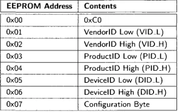
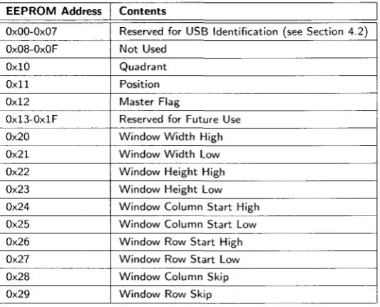
4.4 Control Board Communication 40 4.5 EEPROM Memory Map 41 4.6 USB2.0 Camera Linux Device Driver 42
5 S y s t e m Control Board 48
5.1 Hardware Design 48 5.1.1 Isolation Circuits 49 5.1.2 Driving Circuits 51 5.1.3 MCU Selection 51 5.1.4 Power Regulation Circuit 54
5.1.5 Electrically Controlled Pneumatic Valve Control Circuit 54
5.1.6 Stepper Motor Controller Control Circuit 56
5.1.7 LED Lighting Control Circuit 57 5.1.8 Proximity Sensor Input Circuit 58 5.1.9 Camera Triggering Circuit 59
5.1.10 I2C Expansion Circuit 59
5.1.11 PC Soft Power and Sense Circuits 61
5.1.12 I2C Bus Switch Circuit 61
5.1.13 Emergency Stop Input Circuit 64 5.1.14 RS-232 Communication 64 5.2 System Control Board PCB Layout 65
5.2.1 gEDA Open-Source Tools 66
5.2.2 PCB Fabrication 66 5.2.3 PCB Population 67 5.3 P C I/O Expansion Board 67 5.4 Firmware Development 71
5.4.1 Functional Requirements 73
5.4.2 Motor Control 73 5.4.3 Motor Ramping Control 76
5.4.4 Camera Trigger Control 77
5.4.5 I2C Master 78
5.4.6 I2C Slave 80
5.4.7 I2C Bus Switch 80
5.4.8 Job Queue 81
5.4.9 I2C I/O Expansion Board Control 84
5.4.10 I2C Expansion Interrupt Control 85
5.4.11 I2C LCD Control 86
5.4.14 Capsule Tracking and Counts 90
5.4.15 Heartbeat Timer 90 5.4.16 Debug Mode Timer 90
6 Host P C 92
6.1 Operating System Selection 92
6.2 Hardware Selection 93
6.3 Software 94 6.4 inspect 94
6.4.1 POSIX Threads 95
6.5 fpgaJoaderss 101 6.6 camJnit 102 6.7 pyWindowConfig 103
6.8 pyCamCal 104 6.9 W32 Control Panel Application 104
6.10 Data Collection 105 6.11 File Organization 106
6.12 Start Up 107 6.12.1 inittab 107 6.12.2 Firmware Loading Script 107
7 Assembling t h e Prototype 109
7.1 Wiring 109 7.1.1 USB2.0 Camera I l l
7.2 Firmware I l l 7.3 Host PCs I l l
7.3.1 Operating System I l l
7.3.2 Software 113
8 Recommendations and Conclusions 114
References 119
A Control Board Design Reference 122
A.l Control Board Schematics 122
B U S B 2 . 0 Camera F X 2 Firmware 140
B.l Cypress EZ-USB FX2 Vendor Requests 140 B.2 Micron Image Sensor Register Definitions 141
B.2.1 mLregs.h 141 B.3 FX2 Firmware 142
B.3.1 Makefile 142. B.3.2 fx2cam_common.h 143
B.3.3 fx2cam_ids.h 144 B.3.4 fx2cam_i2c-addr.h 145 B.3.5 fx2cam_usb.h 145 B.3.6 .startup.a51 146 B.3.7 usb_descriptors.a51 147
B.3.8 vectors.a51 151 B.3.9 eeprom_regs.h 151 B.3.10 fx2cam_common.c 151 B.3.11 fx2cam_main.c 153
C U S B 2 . 0 Camera Linux Driver 164
C.l IMGUSB Fast USB Class 164
C.l.l imgusb.h 164 C.1.2 imgusb.cc 165 C.2 PM_CAM USB Primatives 167
C.2.1 pm_prims.h 167 C.2.2 pm_prims.cc 168 C.3 PM^CAM USB2.0 Camera Driver Class 170
C.3.1 pm.cam.h 170 C.3.2 pm_cam.cc 172
D S y s t e m Control Board Firmware 185
D.l common.h 185 D.2 job_ids.h 190 D.3 main.c 190 D.4 i2c_slave.h 220 D.5 i2c_slave.c 221 D.6 i2c_commands.h 223
D.8 i2c_2.c 223 D.9 i2c_io_exp.h 227 D.10 i2c_io_exp.c 227 D . l l lcd_i2c.h 228 D.12 lcd_i2c.c 229 D.13 uart_commands.h 233
D.14 uart2.h 234 D.15 uart2.c 234
E H o s t P C Software 237
E.l inspect 237 E.l.l Makefile 237
E.1.2 inspect.h 238 E.l.3 inspect.cc 239 E.l.4 inspect.conf 261
E.2 t e s U p 261
E.2.1 test_ip.cc 261
E.3 camJnit 263 E.3.1 Makefile 263 E.3.2 cam_init.cc 263 E.4 fpga_loader_ss 271
E.4.1 Makefile 271 E.4.2 fpga_loader_ss.cc 271
E.5 pyWindowConfig 279 E.5.1 pyWindowConfig.py 279
E.6 pyCamCal 285 E.6.1 pyCamCal.py 285
E.7 Human Machine Interface (w32) 290
E.7.1 frmMain.frm 290 E.7.2 modGUIConsts.bas 312 E.7.3 modCSVParser.bas 312 E.7.4 modUARTCommands.bas 313
List of Figures
2.1 OptiSorter 6 2.2 OptiSorter Quadrant Birds-Eye View 7
2.3 USB Bus Topology 12 2.4 USB Standard Connectors 17
2.5 I2C Sample Schematic 20
2.6 I~C Timing Diagram 21
3.1 Conceptual block-diagram of the PharmaSorter 25
4.1 Micron Evaluation Board Block Diagram 33 4.2 USB2.0 Camera High Level Block Diagram 35
5.1 System Controller Block Diagram 49 5.2 Typical Optocoupler Circuit Symbol 50
5.3 Common Isolation Circuit 50 5.4 Isolation Driving Circuit - Sinking 52
5.5 Isolation Driving Circuit - Sourcing 52 5.6 Counter Electromotive Force Protection Circuit 55
5.7 Pneumatic Valve Control Circuit 55
5.8 Motor Control Circuit 56 5.9 LED Lighting Control Circuit 58 5.10 Proximity Sensor Input Circuit 58 5.11 Camera Trigger Driver Circuit 59
5.12 I2C Buffered Expansion Circuit 60
5.13 I2C Buffered Expansion Interrupt Circuit 60
5.16 I2C Bus Switch Circuit 63 5.17 E-Stop Input Circuit 64 5.18 RS-232 Transceiver Circuit 65 5.19 Populated System Control Board PCB 68
5.20 I2C I/O Expansion Board Input Circuit 69
5.21 I2C I/O Expansion Board Output Circuit 69
5.22 I2C I/O Expansion Board I2C Address Select Circuit 70
5.23 I2C I / O Expansion Board Input Circuit 71
5.24 I2C I/O Expansion Board 72
5.25 Motor Pulse Control flow diagram 75 5.26 Proximity Sensor Interrupt flow diagram 76 5.27 Flow Diagram of Bus Switch Interrupt Service Routine 82
6.1 PC Mounting Scheme 94 6.2 Inspect Software Scheduling Scheme 95
6.3 Inspect Main Flow Diagram 97 6.4 Inspect Image Acquisition Flow Diagram 98
6.5 Inspect Image Processing Flow Diagram 100
6.6 Inspect HTML Output File 101 6.7 pyWindowConfig Screen Shot 104 6.8 pyCamCal USB Device Selection Screen Shot 104
6.9 pyCamCal Main Window Screen Shot 105 6.10 W32 Control Panel Application Screen Shot 106
7.1 Panel Layout (Front) 110 7.2 Panel Layout (Rear) 110 7.3 High-Level Wiring Diagram 112
2.1 USB Control Request Setup Packet 13 2.2 USB Control Request bmRequestType BitMap 13
2.3 USB Control Requests 14 2.4 USB Device Classes 15 2.5 USB pin out 17 2.6 Frequently Uses libUSB Functions 19
3.1 Digital Interface Comparison 26
4.1 Cypress CO Load - Descriptor Values Only 36 4.2 Cypress C2 Load - Descriptor Values and Firmware 36
4.3 USB2.0 Camera EEPROM Memory Map 41
4.4 pm_usb Class Functions 44 4.5 pm_prims Primitive USB Functions 45
4.6 irngUSB Class Functions 47
5.1 System Control Board MCU Requirements 53
5.2 dsPIC I2C Master Functions 79
5.3 UART Command Format 88 5.4 UART Commands 89
6.1 Host PC Hardware 93 6.2 USB2.0 Camera Position Identifiers 103
CCD CMOS DID FOV FPGA GNU GPL I2C LCD LED Mbps MCU OS PAL PC PCB PID URB USB VID
Charge Coupled Device.
Complimentary Metal Oxide Semiconductor. Device ID.
Field of View.
Field Programmable Gate Array. GNU's Not Linux.
General Public License. Inter-Integrated Circuit. Liquid Crystal Display. Light Emitting Diode. Mega-bits Per Second. Microcontroller. Operating System. Phase Alternating Line. Personal Computer. Printed Circuit Board. Product ID.
Introduction
The manufacturing of two-part gelatin capsules requires a highly controlled process to ensure the resulting product is of optimal quality. The customer expectation is that the product is free of functional as well as of aesthetic defects. It is not possible however, to have absolute control over every aspect of the manufacturing process and as a result, defects are inevitable. To ensure the end-product is free of flaws, some means of quality control are required. Although, one of the most influential facets for quality control is cost. The profit made from the sale of an individual capsule is very small and thus the cost and time devoted to the inspection of each individual capsule should reflect this.
1.1 Current Quality Control Methods
more expensive than a high-quality, reliable automated inspection system.
1.2 Automated Vision Solution
In contrast, automated vision systems require significant start-up costs and development time. A vision system needs to be planned out, built and tested before it can be used in a quality control situation with confidence. Once built and verified, however, an automated vision system can provide consistent, objective inspection. It can also run indefinitely without breaks, aside from regular scheduled maintenance or downtime for repairs. However, a vision system does require a consistent environment to perform inspection, unlike humans that can easily adapt to changes in lighting or product. Even slight environmental changes can be detrimental in the performance of an automated vision system. For the inspection of two-part gelatin capsules, which are produced in various sizes and colours, specific inspection algorithms and parameters must be tailored to each specific capsule type. Although, once developed, an automated inspection system is a much more cost effective and accurate means of quality control than manual inspecting.
The cost devoted to the inspection of each individual capsule is very small arid this must be considered for a machine vision system to replace a human worker, this must be considered. Devel-oping nations clearly have an advantage in ensuring their product is of high quality since the cost of manual inspection is a very small component of the overall cost of the product. Thus for North America to compete, where labour costs are substantially higher, an automated inspection system is a practical solution to quality control. Automated inspection systems exist for the inspection of two-part gelatin capsules, however the expense of such a unit cannot always be warranted.
1.3 Typical Manufacturing Defects
1.4 State of t h e Art
A machine vision system requires a single setup cost as well as possible maintenance costs. Typical systems available on the market cost in the range of $500,000 [1]. Two big names in the hard capsule inspection business are Daiichi Jitsugyo Viswill Co. and Eisai Machinery USA Inc. Each of these companies offer inspection systems for two-part hard gelatin capsules, along with other pharmaceutical products. The Daiichi Jitsugyo Viswill CVIS-SXX-E system is capable of inspecting number 1 through 5 sized uni-colour and bi-colour hard capsules, excluding transparent and dark capsules [5]. Their system performs an inspection on the circumference surface of the cap and body with a inspection capacity of 1700 to 2500 capsules per minute [5]. The CVIS-SXX-E uses high-resolution CCD line sensor cameras and is capable of detecting a minimum size flaws of lOOmum
[5]. Eisai Machinery offers three models of capsule inspection systems, rated at 800, 1600 and 2500 capsules per minute. The Eisai system uses CCD cameras for inspection, but the capsule sizes and colours supported are not mentioned. Therefore, while the current current state-of-art capsule inspection systems do exist they are quite expensive.
1.5 Motivation
The overall goal of this project is to design and develop a working prototype for a full custom capsule inspection system. The system developed must be capable of a target inspection rate of 1000 capsules per minute. For the prototype system, the focus was on only the inspection of size-0 natural two-part hard gelatin capsules, which is the most popular capsule sold by Pharmaphil Inc. After the completion of the proof-of-concept stage, sound evidence that such a system is plausible permitting further development towards a commercial system. Thus the objective of the project was to complete the proof-of-concept stage with a working prototype.
1.6 Design Strategy
project as the PharmaSorter, although a formal name for the system has not been decided upon by Pharmaphil.
The approach taken in solving this problem was to develop a full-custom design in order to reduce cost. By recycling as many components of the OptiSorter as possible, the end cost of the system was reduced significantly. The full-custom design involved the design of custom USB2.0 cameras with the development of the associated drivers and software and the design of a system controller to interface with the mechanics of the system including motor, actuators and sensors. Custom software running on standard desktop PCs was developed to facilitate analysis of images acquired. The full custom approach deemed successful in reducing cost and the result was a proof-of-concept prototype from which the first generation commercial unit can be designed.
The research project involved the collaboration of three students in the Department of Electrical and Computer Engineering at the University of Windsor. The development of the prototype system was divided into three sections, namely: machine control and data acquisition, camera hardware and real-time image processing, and image analysis using image processing. The research team was comprised of myself, responsible for machine control and data acquisition, Anthony C. Karloff, responsible for camera hardware design and real-time image processing and Mohammed J. Islam who developed the image analysis algorithms using image processing.
This thesis outlines the personal contributions made to the project. This includes the detailed design of various components of the system including detailed hardware design, firmware and software development. Supplemental documents including technical reference manuals of various hardware are companion to this thesis and are referenced accordingly. Source code listings for the firmware and software developed for the prototype system are included in Appendix Chapters B through E.
Background
This chapter is intended to provide the reader with some background information on some of the technologies used in the development of the system. The development of the PharmaSorter proto-type was accelerated by reusing an the mechanics of an existing capsule inspection system called the OptiSorter. Background information regarding the OptiSorter is presented in this section including the capsule loading and ejection mechanism, and electrical hardware that was reused in the prototype design. For the prototype system, custom USB2.0 cameras were developed and custom firmware and drivers were created. USB2.0 is a fairly involved technology although many semiconductor vendors offer devices to reduce development time and complexity. The basics of USB2.0 are presented here. Although I2C is not a complicated communication interface, it does deserve some recognition due to the abundant use in the prototype system. I2C is a two-wire serial communication interface intended for chip-to-chip communication.
2.1 OptiSorter
The inspection of any object using a computer vision requires the development of a mechanical system to load, fixture and eject the object in addition to the electrical hardware and software. For the development of the PharmaSorter, an existing mechanical structure was used to facilitate this requirement. The OptiSorter, shown in Figure 2.1, is a machine vision system developed in the early-to-mid nineties for purpose of inspecting two-part pharmaceutical capsules.
Figure 2.1: OptiSorter
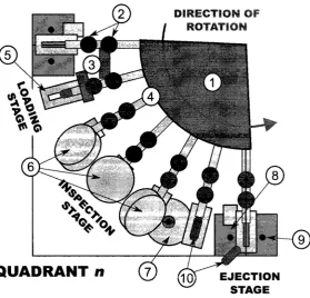
valves are used to eject the capsule into either a pass or fail discharge mechanisms. The OptiSorteris comprised of four identical inspection quadrants operating in parallel. The components of a quadrant are labelled in Figure 2.2 accompanied by a detailed description of the OptiSorter's components including the electrical and mechanical systems.
1. Rotating Disc The rotating disc is the base of the loading hopper with slots to allow capsules
to be queued in each arm (4) which are fixed to the disc.
2. Capsule Intake Lever The capsule intake lever controls the flow of capsules entering the holder
(5). Two holders are used to allow a single capsule to be loaded onto the holder at a given time.
3. Lifters The lifters are fixed metal blocks used to lift the intake levers (2) to allow a capsule to
Figure 2.2: OptiSorter Quadrant Birds-Eye View
the holder and another held in the waiting position while the rest are queued single file in the arm (4).
4. A r m The arms are hollow metal shafts that hold the capsules in the inspection queue. The; arms are the link between the hopper and the holder (5) and rotate to move the capsule through the various stages of the inspection process.
5. Capsule Holder The capsule holder is a machined steel block with a grove to hold the capsule
and a slot allowing for the bottom portion of the capsule to be visible. The capsule rests on the holder while is passes through the various stages.
6. Top View Cameras The top view cameras, comprised of a left, center and right camera,
ac-quire images of the top surface of the capsule. The cameras are triggered when the holder enters their field of view.
7. B o t t o m View Camera A single camera is positioned to acquire an image of the bottom of the
8. Accept Ejection An electrically controlled pneumatic valve is used to eject a passed capsule
using a burst of air.
9. Reject Ejection A constant supply of air is used to reject all capsules not passed (assumed
fail).
10. Two-Part Capsule The capsule is the object being inspected. A given machine can only
support a single size capsule but by modifying inspection algorithms and machine parameters, various different coloured capsules can be inspected.
The OptiSorter provides a suitable base for performing inspection with the ability to replace the electronics and incorporate more advanced inspection methods. The existing mechanical structure is suitable for the throughput requirement and provides an adequate inspection environment. By re-using the OptiSorter, the upgraded system is cost effective and provides a reasonable inspection.
2.1.1 Mechanical Design
Capsule Loading
The OptiSorter has a relatively simple, yet elegant mechanical design. The mechanics of the system rely on a single stepper motor which rotates a series of 24 arms which load and fixture the capsule for inspection. Each mechanical arm is hollow with a diameter slightly larger than a capsule. The arm queues capsules in single-file from a large hopper atop the machine. As each arm rotates, two levers are used to load an individual capsule into the capsule holder and the waiting position. The levers are activated by lifters located prior to the inspection stage. As the arm enters an inspection area, the first lever is lifted to allow a single capsule to be queued between the two levers in the waiting position. After a short distance, a the second lever is lifted to allow the queued capsule to rest in the holder. The dual plunger system is in place to ensure only a single capsule is loaded at a given time.
Capsule Holder
so the position of the arm is always known. This is essential to properly organize the sequence of events required for inspection.
Capsule Ejection
After the capsule passes the inspection stage it enters the ejection stage where the capsule is ejected into one of two ejection chutes. The ejection of a passed capsule is performed by an electrically controlled pneumatic valve that uses a burst of air to eject a capsule. For a rejected capsule, a constant stream of air is used to eject the capsule into the reject chute. Following ejection, the capsules rest on a metal disc that rotates at a reduced speed proportional to the speed of the arms. The capsules collect on the disc in one of two slots, accepted or rejected. As the disc rotates, the capsules are finally discharged at one of the two exits.
2.1.2 Electrical Design
The OptiSorter's electrical system is quite dated by today's standards, however some components of the existing electrical system can be reused in the re-design. The OptiSorter was mostly comprised of custom electronics including cameras, acquisition boards and an input/output board as well as sensors, actuators and a stepper motor. There were several power supplies used in the system to provide the power requirements of different components. Finally, a simple HMI was designed using several push-buttons and a character LCD.
Power Supplies
To adequately meet the requirements of the system, several power supplies were used. A 24VDC supply was used to operate the motor, the electrically controlled pneumatic valves and proximity sensor. A set of standard PC power supplies were used to provide power for the acquisition boards and cameras. A set of custom designed 8VDC and + / - 15VDC were also used in the system. It is presumed that these were used for an analog portion of the image acquisition system.
Illumination
Cameras and Acquisition
The OptiSorter is equipped with 16 cameras, four for each of the inspection quadrants. The cameras, presumably black-and-white, have a custom circuit board with a custom enclosure and a commercial lens. The wiring of the cameras infers that the cameras produce an analog signal, most probably PAL. For each camera, an acquisition and processor board is used to acquire the images and perform inspection. Each of the acquisition boards is equipped with an equivalent 80286 processor and other signal processing semiconductor devices. Each acquisition board is connected to a large bus where the input/output board also resides. It is presumed that following an inspection, the pass/fail signal is sent to the input/output board which signals the pneumatic valves to accept or reject a given capsule.
Stepper Motor and Controller
The OptiSorter uses a five-pole stepper motor to rotate the capsule holder arms. The stepper motor is controlled by a motor controller. The motor controller accepts a direction signal and steps on the rising edge of the input step pulse. This makes motor control rather straightforward and requires little feedback to track the position of the arms. The motor controller operates at 24VDC and requires a 24V pulse to step.
Proximity Sensor
A single proximity sensor is used as feedback of the position of the holder arms. When the holder enters the inspection area, a pulse is seen from the proximity sensor. This, along with the knowledge of the number of pulses applied to the stepper motor, is used to track the position of the holders.
Electrically Controlled Pneumatic Valves
Electrically controlled pneumatic valves are used to eject the accepted capsules. The valve is engaged (opened) by a 24VDC supply voltage. A single valve exists in each inspection quadrant and is opened according to the pass/fail result of the inspection by the input/output board.
H u m a n Machine Interface
Monitor
A television unit placed atop the machine is presumed to be used for system calibration. A series of switches used to select a camera exists on the side of the machine. A particular camera can be selected and viewed on the television unit. It is assumed that a PAL signal directly from each camera is displayed and used for the calibration of lens focus, camera position, etc.
2.2 Universal Serial Bus (USB)
Universal Serial Bus (USB) is a hi-speed interface used for connecting peripheral devices to a com-puter, or any host system. USB is abundantly available and most modern PCs are equipped to support it. USB devices are also widely available in commercial electronics and commonly used in industry. It is a preferred solution due to it's hot-swap capability, supply capabilities and high speed transfer ability. Developing a USB device requires a working knowledge of the physical, protocol and software levels of the interface.
USB replaces legacy interfaces including serial and parallel ports on PCs. Standard devices like printers, scanners, mice and keyboards now connect using USB. Among these device, many other devices a.re being supported such as PDAs, mobile phones and other hand-held devices. USB is a serial bus interface first introduced in November 1995 with the initial release USB 1.0 by Microsoft, Intel, Philips and US Robotics [39]. USB 1.1 was later released in 1998 to rectify the adoption problem from the initial release [39]. The most current release of USB is version 2.0, which was led by Hewlett-Packard, Lucent, Microsoft, NEC and Philips [36].
2.2.1 Overview
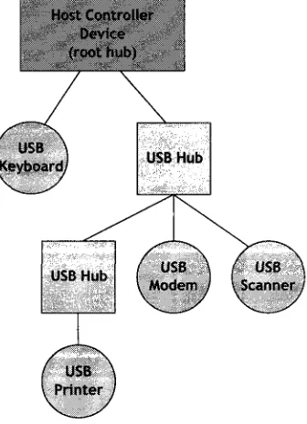
The Universal Serial Bus is a star topology with a single master on the bus, the host. A device on a USB bus cannot initiate a transfer to a host; it must be requested by the host prior to transmission. USB supports the addition of HUBs to the topology to support additional devices. Up to five tiers of HUBs are permitted supporting, up to 127 devices on a single bus. There is a single root hub in any given topology which is integrated directly into the USB host controller device of the host system. A example USB bus topology is shown in Figure 2.3.
Figure 2.3: USB Bus Topology
to the direction of data flow with respect to the host. There in an exception however, with end-point zero (EPO), which is a required endend-point used for device configuration. Endend-point zero is a bi-directional control endpoint required in all devices. This is used for device configuration during the enumeration process and is also often used for vendor specific requests.
2.2.2 Enumeration
Endpoint Zero
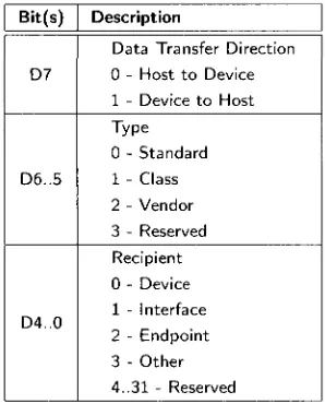
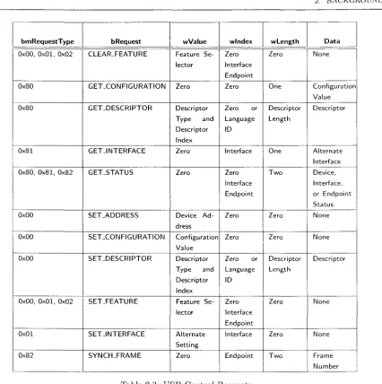
It is essential that all devices support a common mechanism for accessing device information. This is accomplished using the default control endpoint which exists on all devices. This endpoint is bi-directional (IN and OUT) with endpoint address 0. During enumeration, this endpoint is queried for standard device information including vendor and product identification, device class and power requirements. This is accomplished by standard descriptor requests from a device, it's interfaces and the endpoints of each interface. This is performed using the default control pipe. A control request is formatted as described in Table 2.1 where the bmRequestType bitmap is detailed in Table 2.2. The specific configuration data is acquired through a series of requests as described in Table 2.3.
Offset 0 1 2 4 6
Field
bm Req uestTy pe bRequest
wValue wlndex wLength
Size
1 1 2 2 2
Value
B i t M a p Value Value Index Count
Description
Description of Request (Type, Direction & Recipient) Specific Request
Specific t o Request
Used by request t o pass and index
Number of bytes to transfer in data stage (if present)
Table 2.1: USB Control Request Setup Packet
Bit(s)
D7
D6..5
D4..0
Description
Data Transfer Direction 0 - Host t o Device 1 - Device t o Host Type
0 - Standard 1 - Class 2 - Vendor 3 - Reserved Recipient 0 - Device 1 - Interface 2 - Endpoint 3 - Other 4..31 - Reserved
Table 2.2: USB Control Request bmRequestType BitMap
2.2.3 Host Controller Interface
bmRequestType
0x00, 0x01, 0x02
0x80
0x80
0x81
0x80, 0 x 8 1 , 0x82
0x00
0x00
0x00
0x00, 0 x 0 1 , 0x02
0x01 0x82 bRequest CLEAR-FEATURE GET_CONFIGURATION GET_DESCRIPTOR
G E T J N T E R F A C E
GET_STATUS SET_ADDRESS SET-CONFIGURATION SET_DESCRIPTOR SET-FEATURE SET-INTERFACE
S Y N C H - F R A M E
wValue Feature Se-lector Zero Descriptor Type and Descriptor Index Zero Zero
Device A d -dress Configuration Value Descriptor Type and Descriptor Index Feature Se-lector Alternate Setting Zero wlndex Zero Interface Endpoint Zero Zero or Language ID Interface Zero Interface Endpoint Zero Zero Zero or Language ID Zero Interface Endpoint Interface Endpoint wLength Zero One Descriptor Length One
T w o
Zero Zero Descriptor Length Zero Zero
T w o
Data None Configuration Value Descriptor Alternate Interface Device, Interface, or Endpoint Status None None Descriptor None None Frame Number
Table 2.3: USB Control Requests
2.2.4 Device Classes
In an effort to reduce the dependence of devices on individually specific drivers, USB device classes alleviate this by creating standard classes to which a device can belong. By belonging to a given device class, the device must follow the standards specified by said class. A device class can be supported by a single device driver without the need for a fully custom driver for each specific device. Thus the same driver can be used for many unique devices. Commonly known device classes include HID (Human Interface Device) and Mass Storage device used for keyboards and flash disks respectively. A more thorough list of device classes and examples are listed in Table 2.4.
Base Class 0x00 0x01 0x02 0x03 0x05 0x06 0x07 0x08 0x09 OxOA OxOB OxOD OxOE OxOF OxDC OxEO OxEF OxFE OxFF Descriptor Usage Device Interface Both Interface Interface Interface Interface Interface Device Interface Interface Interface Interface Interface Both Interface Both Interface Both Description
Indicate that interface descriptors are t o be used for the device.
Used for audio compatible devices. This can be used in the audio interface of a webcam device.
Communication and CDC Control device used in devices such as ethernet adaptors, modems, etc.
Human Interface Device. This device class is reserved for devices such as mice and keyboards.
Physical device class. This class is used in force feedback joysticks.
Still Imaging device class. Sometimes used for digital cameras, but most use Mass Storage Device.
Printer device class is used for printers and multi-function printer/scanners.
Mass Storage Device is used for USB flash drives, external D V D Drives, etc.
USB Hub class is used for full and high speed USB hubs. CDC-Data class is used w i t h the communication device class
Smart Card Class is reserved for USB smart card readers Content Security interface class
Video interface class - used for video devices like web cams Personal Health care class
Diagnostic Device - used in USB 2.-0 Compliance testing apparatus
Wireless controller - used for WiFi and Bluetooth adapters Miscellaneous - Such as Active Sync devices or Palm Sync devices.
Application Specific - use for Device Firmware Upgrade, IRDA bridge device, etc.
Vendor Specific
2.2.5 D a t a Flow T y p e s
USB s u p p o r t s four distinct d a t a transfer types: control, bulk, interrupt and isochronous. Each
transfer t y p e is suitable for a particular application. A USB transfer occurs between t h e device
driver and an endpoint and t h u s each e n d p o i n t is defined as one of t h e four flow t y p e s in a single
direction (IN or O U T ) . T h e transfer of d a t a between t h e host software and t h e device endpoint
occurs over a logical channel, often referred t o as a pipe. An endpoint may be defined as one of t h e
following d a t a flow types.
C o n t r o l T r a n s f e r
T h e control endpoint is used t o configure t h e device during enumeration and also for controlling
other device-specific functionality. Control endpoints are usually reserved for control and s t a t u s
operations where d a t a is non-periodic. T h e m a x i m u m d a t a size of a control e n d p o i n t is 64 bytes for
USB 2.0 (high-speed) and full-speed devices, b u t only 8 bytes for low-speed devices. This transfer
t y p e is guaranteed and therefore occurs w i t h o u t loss of d a t a .
B u l k T r a n s f e r s
Bulk endpoints are used when large a m o u n t s of d a t a are to be transferred, as for printers, scanners
or external hard-disks. Bulk transfers are g u a r a n t e e d by built-in error detection t o ensure reliable
d a t a transfer. This is accomplished by using error detection via C R C and invoking h a r d w a r e retries
if required due t o delivery failure or bus errors. A bulk transfer is guaranteed for integrity b u t not
for transfer r a t e . T h e b a n d w i d t h utilization is d e p e n d e n t on the bus activity and will vary. For USB
2.0, t h e m a x i m u m bulk transfer size is 512 bytes and 64 bytes for full-speed endpoints.
I n t e r r u p t T r a n s f e r s
An i n t e r r u p t endpoints is designed for devices t h a t do not frequently send or receive d a t a . T h e
i n t e r r u p t endpoint s u p p o r t s b o u n d e d service periods meaning t h e service time is g u a r a n t e e d . T h e
m a x i m u m payload size of an interrupt e n d p o i n t is 1024 bytes for USB 2.0 and 64 bytes for full-speed.
I s o c h r o n o u s T r a n s f e r s
Isochronous transfers are typically used for periodic and continuous d a t a transfer between t h e host
2.2.6 U S B C o n n e c t o r s a n d Cabling
So far, the protocol level has been introduced. The USB specification [36] also contains the connector requirements, cabling, isolation, etc. This information is relevant to the overall layout and design of a system from a hardware design viewpoint and the logistics of the cabling. USB connectors arc standard and well designed. They were specifically designed to permit easy insertion and removal with the. inability to incorrectly attach. The connectors are robust unlike some predecessors with pins that can be bent or broken if not properly inserted. There are several standard types of USB connectors divided into two classes, A-type connectors and B-type connectors. A-type connectors are reserved for the host side and B-type connectors are reserved for peripherals. Figure 2.4 illustrates the common USB connectors used [39].
Type A Type B
4 x 3 2 1 4 x 3 2 1
Mini-A Mini-B
Figure 2.4: USB Standard Connectors
USB cabling is restricted to a maximum of 5 meters (16.4 feet) without the use of hubs. If hubs are used, the maximum distance is about 25 meters since the maximum cable length between hubs is 5 meters with a maximum of 5 tiers of hubs. If the USB cable is too long, the host will not receive the data packet on time and the command will be lost. The cable length is based on the round trip delay of an electrical signal in the length of copper wiring and is also dependant on the quality of the cable. A USB cable is comprised of four wires (sometimes five) with a ground shielding. The data lines are a twisted differential pair to reduce crosstalk. The wiring pin out of a USB cable is shown in Table 2.5.
Pin
1 2 3 4
Name
V s t / s
D-D+
GND
Colour
Red W h i t e Green Black
Description
+ 5 V Bus Power
Differential Data Negative Differential Data Positive Ground
2.2.7 B u s Power
The USB cable provides 5V power (with a 5% tolerance) to peripheral devices. When a device is initially connected, the host reserves 100mA supply which can be later increased after enumeration for a maximum current of 500mA. There is an exception in battery charging devices whereby the USB host can provide up to 1.5A worth of current. Devices that require more power must be externally powered.
2.2.8 U S B Device Drivers
A device driver is software that is responsible for interfacing with hardware. It is operating system dependent and is designed for specific hardware. The driver is responsible for sending commands to hardware and the interchange of data.
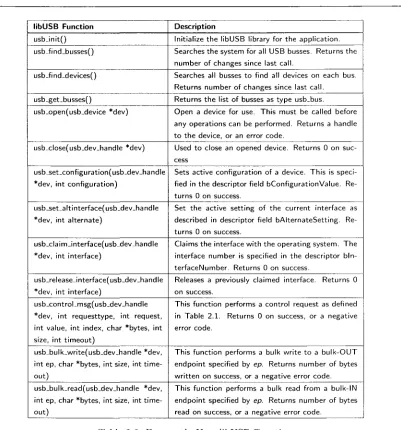
For the Linux operating system, several types of drivers can be developed. A driver can be part of the kernel or a loadable kernel module. These types of drivers require an extensive knowledge of the operating system. However, a user-space driver can be developed to interface with a device that requires less understanding of the operating system kernel. A user-space driver can be safer in that a poorly written driver cannot affect the kernel as severely, or cause it to panic. LibUSB is a cross-platform library of user-space routines for controlling USB devices without the need for kernel drivers. LibUSB is currently available for Linux, MS-Windows, Mac-OSX, and FreeBSD.
libUSB
libUSB Function
usbJnitQ usb_find_busses()
usb-find-devices()
usb-get_busses()
usb_open(usb_device *dev)
usb-dose(usb_dev_handle *dev)
usb_set_configuration(usb_dev_handle *dev, int configuration)
usb_set-altinterface(usb.dev_handle *dev, int alternate)
usb_claim_interface(usb_dev_handle *dev, int interface)
usb_releaseJnterface(usb_dev_handle *dev, int interface)
usb_controLmsg(usb_dev_handle *dev, int requesttype, int request, int value, int index, char *bytes, int size, int timeout)
usb_bulk_write(usb_dev-handle *dev, int ep, char *bytes, int size, int time-out)
usb_bulk_read(usb_dev_handle *dev, int ep, char *bytes, int size, int time-out)
Description
Initialize the libUSB library for the application. Searches the system for all USB busses. Returns the number of changes since last call.
Searches all busses t o find all devices on each bus. Returns number of changes since last call. Returns the list of busses as type usb_bus. Open a device for use. This must be called before any operations can be performed. Returns a handle t o the device, or an error code.
Used t o close an opened device. Returns 0 on suc-cess
Sets active configuration of a device. This is speci-fied in the descriptor field bConfigurationValue. Re-turns 0 on success.
Set the active setting of the current interface as described in descriptor field bAlternateSetting. Re-turns 0 on success.
Claims the interface w i t h the operating system. The interface number is specified in the descriptor bln-terfaceNumber. Returns 0 on success.
Releases a previously claimed interface. Returns 0 on success.
This function performs a control request as defined in Table 2 . 1 . Returns 0 on success, or a negative error code.
This function performs a bulk write t o a b u l k - O U T endpoint specified by ep. Returns number of bytes written on success, or a negative error code. This function performs a bulk read from a bulk-ll\l endpoint specified by ep. Returns number of bytes read on success, or a negative error code.
Table 2.6: Frequently Uses libUSB Functions
2.3 I
2C
I2C (Inter-Integrated Circuit) is a serial bus developed by Philips for connecting low-speed periph-erals of an embedded system. The I2C bus is a bi-directional two-wire multi-master bus used for connecting microcontrollers or processors to devices or other processors.
example configuration of a single master I2C bus with several slave devices is shown in Figure 2.5.
SCL SDA
Microcontroller (slave)
Figure 2.5: I2C Sample Schematic
The addressing scheme for I2C slave devices consists of a 7-bit address space with 16 reserved addresses resulting in a maximum of 112 nodes for a given bus. A typical slave device has fixed high address bits and several inputs to select the lower address bits (typically three bits). This allows the designer to use multiples of the same device on a single bus with distinct addresses.
The I"C bus most commonly operates at 100 kbit/s, known as standard mode. More recent revisions of the I2C specification include faster operating speeds including Fast Mode at 400 kbit/s, Fast Mode Plus at 1 Mbit/s and High Speed Mode at 3.4Mb/s. The High speed mode of operation typically requires current sources rather than simple pull-up resistors to permit faster rise times.
Since the lines of the I2C bus are driven by open-drain drivers, the pull-up resistors are needed to pull the line voltage to Vcc- If a device wishes to communicate on the bus, the line is pulled to ground to communicate a logical zero, and allowed to float to represent a logical one. The master(s) on the bus are responsible for providing a clock, however with clock-stretching, slaves arc able to momentarily pause the transfer of information if required. Clock-stretching occurs when the slave holds the SCL line low for longer than the clocked frequency. The master must read the clock line after releasing it to ensure it has been pulled high, if not, the master must wait until the clock line is high before reading off the data line (SDA).
Since I2C supports multi-master busses, arbitration is required to ensure multiple masters do not attempt to use the bus at the same time. Arbitration in I2C is quite simple and does not give priority to a particular master. The process of arbitration is required if two masters start a transmission around the same time, each transmitter checks the level of the data line (SDA) and compares it to what is expected. If the value on the bus does not match, the particular transmitter loses arbitration and ceases transmission. If two masters are sending messages to two different slaves, the slave device with the lower slave address will win arbitration due to the nature of the bus.
In an I2C transaction, the master initiates transmission by sending a START bit, followed by the 7-bit address of the target slave device, followed by a read/write bit. The read/write bit indicates the direction of data flow with respect to the master: 0 for write and 1 for read. If the slave exists
«-n
Microcontroller (master)
Serial EEPROM (slave)
on the bus, it will respond with an ACK (acknowledge) for the address. An acknowledge by a slave is initiated by pulling the SDA line low for the expected clock which is recognized by the master. The master will then continue in either transmit or receive mode. After the transmission, the master will send a STOP bit indicating the transaction is complete. A master will acknowledge when receiving data by holding the SDA line low after each byte received, except for the last, to indicate the expected amount of data has been received.
The START bit (S) is recognized by a high to low transition of SDA while SCL is high. A STOP bit (P) is recognized by a low to high transition of SDA while SCL is high. A typical 12C transaction timing diagram is shown in Figure 2.6.
START ADDRESS ADDRESS READ/WRITE SLAVE ACK DATA ACKNOWLEDGE STOP
(S) BIT 7 BITS (6..0) BIT BIT BITS (P)
Figure 2.6: I2C Timing Dia gram
I"*C is commonly used in semiconductor devices where simplicity and cost are key factors. Since I2C is a two-wire interface, the pin cost is minimal, resulting in a simple and low cost solution. I2C is common found in serial EEPROMs, low speed ADC and DACs, LCD displays and real-time clock chips. Some manufacturers use what they refer to as a two-wire interface (TWI) that is an adaptation of I2C but not completely conforming to the I2C specification.
2.4 Machine Vision
Machine vision is the encapsulation of computer vision, image processing and machine control to typically perform inspection on manufactured goods in industry. A traditional machine vision system is comprised of cameras, computers and digital inputs and outputs or computer networks for machine control. Machine vision systems are intended to replace human inspectors working on assembly lines to automate the inspection process. Although human inspection is more flexible and adaptive than machine classification, human inspection is subject to inaccuracies due to human attention span and circumstance. Although the human eye is more versatile than any vision system as it can adapt to various illumination conditions, a machine vision system can replace the need for human inspection by producing high quality, objective inspection.
analyzing individual pixels in regions of an image. This portion of machine vision falls under the image processing section. Image processing is a crucial portion of any machine vision system since it is essentially the brains of the analysis. Image processing used in machine vision will typically perform some pre-processing on an image including de-noising and image enhancement. Typically, the majority of the image processing during inspection is performed on binary images following the pre-processing. Some of the common processing methods include pixel counting, thresholding, segmentation, edge detection and template matching. However, it is entirely dependent on the application and will change depending on the object and the environment. An inspection system may check for surface flaws and take measurements to determine the quality of the part.
A typical machine vision system is comprised of one or more digital cameras, typically black and white although colour cameras are gaining popularity, along with the appropriate optics such as lenses and mounts. The majority of any inspection is typically most dependent on the grayscale information and thus a grayscale camera is typically preferred since it enables the highest resolution and faster speed. Some applications, however, require colour information. In this case, a colour sensor is required and the grayscale information is extracted from the RGB colour space. The system must also have an interface to digitize and acquire the image data, typically a frame-grabber or other computer interface such as USB. A processor is required to analyze the image(s) and is often a PC or embedded DSP processor. A device gaining popularity is a smart camera which incorporates all of the above mentioned components into a single camera. The smart camera has a lens, sensor, acquisition hardware and processor all within a single device. Input/Output hardware is required to interface with the machine portion of the system. Sometimes a communication link like an Ethernet or RS-232 connection is used rather than dedicated I/O to report inspection results.
In order to perform inspection, software must be developed to perform the image processing and yield a pass or fail result of the inspection. This is platform dependent and can be accomplished in many different ways. The machine must be equipped with sensors and actuators that when combined are used to locate parts, trigger image acquisition and sort accepted and rejected parts. The system must incorporate means of obtaining the result of inspection from the software in order to properly eject the object.
Design Methodology
The design of any system requires a substantial amount of planning and research before any type of development can begin. The design and development of the PharmaSorter began with a list of high-level requirements and an existing mechanical structure, namely the Optisorter. In order to meet the system requirements, many considerations had to be taken into account: the required inspection rate of the system, the inspection detail requirements (minimum flaw size), the cost constraints and the ability to maximize the reuse of existing hardware.
USB 2.0 CAMERA
(master)
SYSTEM CONTROLLER
USB 2.0 CAMERA
USB 2.0 CAMERA
TUSB USBT
INSPECTION PC
MOTOR CONTROL
LIGHTING CONTROL
ACCEPT/REJECT CONTROL •
USB 2.0 CAMERA
QUADRANT r.
Figure 3.1: Conceptual block-diagram of the PharmaSorter
3.1 Design Approach
The design of the PharmaSorter involved a great deal of initial planning and research. This included assessing the requirements and constraints of the system, and creating a development strategy based on these design criterion. The design approach involved the development of the small components of the project and putting the pieces together until a quality finished product was achieved. This involved building and testing circuits at the breadboard level with the aid of development boards and writing and debugging firmware to verify that the selected devices were suitable for their purpose. This was accompanied by the development of drivers and software to test data rates and ensure the selected hardware was suitable for the application. Building small circuits and writing custom firmware and software was a practical way of testing and verifying designs. Although the initial concepts for each of the design stages were based on educated predictions, it was imperative that they were thoroughly tested and verified. As each component was finalized, they were incorporated into the final prototype.
Due to the requirements and constraints of the system, a fully custom design strategy was taken. This involved designing custom circuits, developing custom firmware and writing many software applications. This was essential to reduce the cost of the system, and reuse many of existing hardware components of the OptiSorter. By undertaking a fully custom approach, the cost of the prototype was minimized, although the design time increased substantially.
3.2 Design Considerations
The primary goal of the design of the system was to upgrade the electronics of the OptiSorter, the driving force for this being the requirement of a low-cost solution. In addition to this constraint, the required system throughput of 1000 capsules per minute was important as was the ability to detect a certain degree of flaws. This means the camera must be able to obtain a minimum amount of detail in the capsule in a certain amount of time.
3.2.1 Data Transfer Medium
A low cost camera solution that met the desired system throughput was sought out. After comparing available technologies in transfer mediums, the USB2.0 interface was selected. A comparison of interfaces is shown in Table 3.1 [6].
Data Transfer Rate Max. Cable Length Max. Devices Connector Capture Board Cost
FireWire 1394.a
400 Mbps 4.5m up t o 63
6 pin Optional Moderate
FireWire 1394.D
800 Mbps up t o 100m
up t o 63 9 pin Optional Moderate
Camera Link
up t o 3.6 Gbps 10m
1 26 pin Required
High
USB 2.0
480 Mbps 5m up t o 127 4 pin (USB)
Optional Low
Gigabit Ethernet
1000 Mbps 100m unlimited RJ45 / CAT5e
Not Required High
Table 3.1: Digital Interface Comparison
3.2.2 I m a g e Sensor
As a cost reduction measure, and to reduce mechanical changes, a custom USB2.0 camera was designed. For the design of the camera it was important that an appropriate sensor was selected. Some of the considerations for the image sensor include the decision between CCD or CMOS, colour or monochrome, resolution requirements and sensor size. After determining the minimum feature size flaw detection requirement, and considering transfer rate and image processing constraints, a colour, 3.1 mega-pixel, 1/2 inch CMOS image sensor was selected. A colour sensor was preferred since the ability to detect capsule colour was important. Although from analyzing the grayscale images, a colour classification can be estimated based on a subset of known colours, a colour sensor will provide more accurate information. The sensor chosen has a maximum resolution of 3.1 mega-pixels with a 4:3 aspect ratio resulting in an image size of 2048x1536 which significantly exceeds the minimum feature size requirement. The physical size of the sensor determines the sensor field of view (FOV) which was selected to roughly match the sensor used in the camera native to the OptiSorter. It was also desirable to have a low-cost sensor that suited the application.
3.2.3 I n s p e c t i o n E n v i r o n m e n t
One of the most important components of a quality machine vision system is the inspection envi-ronment. This includes the illumination, camera angle, immunity to external noise and maximizing viewable area of the capsule. Considerations such as illumination type and wavelength, obstructions in the inspection environment and motion of the capsule are all important in acquiring a quality image. From a machine vision standpoint, the better quality and consistency of the image results in a more accurate and faster inspection.
Illumination
the light thus reducing exposure time and minimizing the effect of motion blur. From this, the light source, wavelength and intensity must be determined. Many lighting sources exist, yet LED is one of the most popular in machine vision applications. LEDs are compact, low-power, rugged, can be strobed and possess a long-life. LEDs come in a variety of wavelengths. The most commonly used in machine vision are red, green, blue and white. Since the recognition of colour is important for the inspection of the capsules, a white LED was selected. Comparing the spectral content of a white LED to the quantum efficiency of the selected sensor, a relatively close match exists between the spectral content of a white LED and the sensitivity of the sensor.
Capsule Holder
The importance of the consistency of the inspection environment must be emphasized. In order for an inspection algorithm to yield consistent inspection results, a uniform environment must exist. The OptiSorter was originally equipped with solid holder which provided a consistent environment for inspection. A clear holder concept was attempted, however due to the sensitivity to scratches and inconsistent machining, they did not provide the consistency required for the application. The initial thought was that the use of a clear holder would permit more viewable area of the capsule through the transparent plastic. After experimental trials however, the inconsistency of the clear holder and the marginal improvement in viewable area was not compelling enough to pursue the idea further. After setting up a reasonable inspection environment, the solid holder provided a consistent environment suitable for performing inspection.
3.2.4 System Control
Another integral component of the system is the system controller. The system controller is essen-tially an input/output board with communication interfaces such as I2C and UART. By taking a custom approach in designing the system controller, the cost can be drastically reduced over select-ing a generic PLC, or other controller, with much more flexibility. The downside of a full custom approach is the extra design and development time. Starting with the requirements of the system controller, component selection began. The speed at which the system must operate, the required outputs and inputs and the information required after inspection were all considerations that were taken into account during the design. In addition, the selection of components had to be reasonable to reduce overall board cost and meet the performance requirements. In selecting the microcontroller of the system controller board, many criteria were considered including speed, size and features. A microcontroller was required that met the system requirements at a reasonable cost.
For this, many devices were researched, purchased and tested to verify their suitability for the desired application. One key consideration was the component cost and complexity.
3.2.5 Power Supplies
Any electrical system requires at least one power supply. For the PharmaSorter, it was desired to maximize the recycling of existing components of the OptiSorter. Unfortunately, the only reusable power supply was a 24V 1A Siemens supply. It was determined that the motor controller and the electrically controlled pneumatic valves required a 24V supply. The LCD panel required a 5V supply, however it appeared that the switches and lamp operated at 24V. The proximity sensor and back-light LEDs required 12VDC to properly function. The system controller board must-control the motor, pneumatic valves, lights, proximity sensor and HMI and thus requires 24VDC and 12VDC supplies. The selected MCU operates at 3.3V and thus must be accounted for. Due to the current supply requirements of the back-light LEDs, a second supply of 12V at 3.6A was used in the PharmaSorter. The 3.3V required for the system controller MCU and other ICs on the system controller board was regulated using a linear regulator from the 12V line. Each of the inspection PCs required an individual standard ATX power supply and thus four 500W power supplies were used for that purpose. The complete hardware for the inspection PCs are detailed in Chapter 6. This power scheme provides adequate power to the separate areas of the system and is more than sufficient for the power demand.
3.2.6 I n s p e c t i o n P C s
allows for easy automated installations and updates. Debian allows one to install a base system without an X-Server or extraneous applications from which the user can install packages they deem necessary. Since the inspection PCs do not need to display any information graphically, they do not require an X-Server to function. The flexibility and mature package management system were the most influential components in the selection of Debian.
USB 2.0 Camera
USB 2.0 is a modern protocol used to interface between computers and external devices. USB is a replacement for the legacy parallel and serial ports which are being phased out of desktop PCs by the computer industry. The main advantages of USB are the ability for multiple devices to be connected to a single USB network and the faster data transfer rates that be achieved with a greater deal of flexibility over serial and parallel ports.
USB devices require much more planning and development than serial and parallel port devices. Each USB device must have a unique identifier, handle a set of standard requests and must adhere to a strict set of rules defined by the USB2.0 specification [36]. It is fortunate however, that many semiconductor vendors provide USB2.0 microcontrollers that ease device development by incorporating the particulars of the USB2.0 specification directly in hardware. An example of one of these devices is the Cypress EZ-USB FX2 series of microcontrollers. The FX2 is a high-speed USB microcontroller with seven user endpoints which allows great flexibility and expandability during the design of peripherals. The selected USB microcontroller for the PharmaSorter USB2.0 cameras is the Cypress EZ-USB FX2LP.
design minimizes component count and board size that even in small fabrication runs, can be achieved at a relatively low cost.
The image acquisition system for the PharmaSorter involved a full-custom hardware design. A full custom approach is a major cost reduction technique since current USB2.0 still cameras for machine vision applications start above $1000USD. A comparable camera from Silicon Imaging, the SI-1300-U, is a USB2.0 colour 3.2 megapixel camera with a cost of around $1300. A full custom design begins with the conceptual design of the system, schematic level design and PCB layout and fabrication. When a hardware device is being designed, it is often easier and cheaper for the designer to find an evaluation system or development kit with the hardware they are considering. Many development kits provide schematics which serve as a validated reference design. For the PharmaSorter, this was indeed a situation where this could be taken advantage of. One of the most significant components of the camera hardware is the image sensor. There are many vendors and many sensors available that vary in image resolution (megapixels), speed and quality. After evaluating the products offered by various vendors, the Micron MT9T001 3.1 megapixel CMOS images sensor was selected [22]. The MT9T001 is low cost, low noise, high quality CMOS image sensor capable of 2048x1536 pixel images with a frame rate of 12 to 93 fps (frame rate depends on window size and resolution) [22].
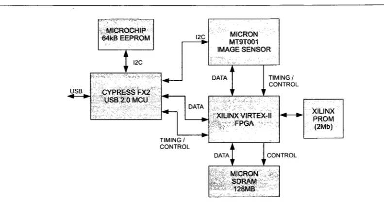
After selecting the image sensor, a Micron evaluation board was purchased that was equipped with the MT9T001 sensor, a Cypress FX2 USB 2.0 microcontroller and a Xilinx VirtexII FPGA. This provided a. good base for developing a custom camera. With the development kit, the various components could be evaluated based on the requirements of the project. It also provides a base design for custom hardware since all development board schematics and component selection were provided. A high level block diagram of the Micron evaluation camera is shown in Figure 4.1.
The Micron evaluation board was equipped with more than required to begin the development of custom firmware and software for the PharmaSorter. By designing custom firmware, the abilities of the evaluation board could be observed and a new hardware design could be tailored to meet the requirements of the project by minimizing component count, overall cost and complexity.
In many cases, full source code for evaluation boards is provided by the vendor. This was not the case however for the Micron camera development board. All firmware and MS-Windows drivers were closed source. Micron did provide documentation for the API they shipped with the device and sample code on using it with various programming languages. This was not terribly useful for the PharmaSorter since the host PCs would be running Linux, not Windows, and would be using custom firmware. However, some aspects of the Micron design posed useful as a reference design.
USB
MICROCHIP 64kB EEPROM
I2C
CYPRESS FX2 USB 2.0 MCU
I2C MICRON MT9T001 IMAGE SENSOR
DATA
TIMING/ CONTROL
TIMING/ CONTROL
XILINXVIRTEX-II FPGA
DATA
XSLINX PROM (2Mb)
CONTROL
MICRON SDRAM
128MB
Figure 4.1: Micron Evaluation Board Block Diagram
evaluation kit. This was useful in determining how the sensor and FPGA were initialized. By using the API documentation and examining the control transfers it was evident that I2C write and read requests were used to configure the image sensor registers. When it came to actually transferring image data, Micron used 1024-byte blocks of data in a USB bulk transfer [23]. In accordance to the USB 2.0 specification, bulk transfers are limited to a maximum transfer size of 512-bytes [36]. The fact that Micron is using a 1024-byte bulk transfer permits lower overhead according to their findings [23].
4.1 Hardware Level Design
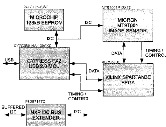
After developing initial firmware and software using the Micron development board, which is de-scribed in detail in the subsequent sections, a finalized hardware design of the camera was developed. From a block diagram level description of the USB2.0 camera board, schematics were designed based on the specifics of the devices used in the design. After thorough analysis of the requirements of the system, a final camera board design was achieved based on the reference design of the Micron evaluation board. The design included a Xilinx Spartan 3E FPGA to replace the Xilinx Virtex II from the Micron reference design. It was determined that the Virtex II was exceedingly powerful for the application. The Spartan 3E provided the more than required logic elements for the firmware developed with adequate block-RAMs for image buffering. The finalized design excluded a SDRAM which was included in the Mircon reference design for image buffering. It was determined that this was unnecessary and the overhead would compromise the target inspection rate. By excluding the SDRAM, the camera is operates in real-time. It was determined that if the transfer rate could not meet the requirements, the image acquisition time would be exceedingly long to meet the timing requirement of the inspection throughput.
An addition to the camera hardware design is the inclusion of a NXP I2C bus extender [29]. The NXP I2C bus extender is an IC that extends the I2C bus by increasing the total system capacitive load to around 3000pF [29]. This permits longer transmission lines between devices on an I2C bus. I2C is used to transfer pass/fail messages to the system controller following an inspection. Although not intended for long distance communication, use of I2C bus extenders buffer the I2C line with higher driving currents that permit long distance communication [29].