M.Tech Student, Department of Electrical and Electronics Engineering, MES College of Engineering, Kuttippuram,
Kerala, India1
Professor and Head of the Department, Department of Electrical and Electronics Engineering, MES College of
Engineering, Kuttippuram, Kerala, India2
ABSTRACT: In this paper a Reusable Launch Vehicle in atmospheric phase is considered. A disturbance observer based PD controller is proposed for controlling the attitude of the system considered. This method is an effective way of achieving disturbance rejection and robustness to plant uncertainties. The disturbance observer based control is used for observing the flexibility dynamics and stabilizing the flexible mode RLV. The disturbance observer makes the actual flexible plant dynamics similar to that of nominal rigid body within a limited frequency range. The classical gain stabilization approach for stabilizing bending mode is also presented. Both methods are compared and advantages of disturbance observer based PD control over the gain stabilized PD control are discussed.
KEYWORDS:Launch Vehicle, flexibility, DOBC, LQR.
I. INTRODUCTION
Reusable launch vehicle (RLV) is capable of launching a vehicle into space more than once. The technical challenges of designing a system to fly to orbit and return are monumental. The dynamic of the vehicle is highly interactive and the vehicle is influenced by a lot of uncertainties. It is also affected by unknown external disturbances. Problems associated other than complex dynamics include path constraints, heat rates, structural loads, and dynamic pressure. Main challenges include the uncertainty and external disturbance induced from the complex atmosphere characteristics. Controller designed for this kind of plants should have rapid adaptability and sufficient robustness.
Gain scheduling was widely employed in flight control systems [1]. The method is not always effective when applied to RLV. Because RLV may need aggressive maneuvering in order to dissipate excessive energy. Also the operation of RLV can be far away from the equilibrium point. Then Dynamic inversion method was used to overcome the disadvantages of Gain Scheduling. Non-linear dynamic inversion (NDI) is a method were we invert the non-linearities and linearize the non-linear system [4]. The robustness properties of the dynamic inversion are questionable especially when considering the uncertainties involved. Incremental dynamic inversion method was able to provide better robustness compared to NDI [3]. The basic idea of the methods is to cancel the nonlinear dynamics via mathematical transformation.
Recently, a high-order SMC technique has been employed in reentry attitude control. Sliding mode disturbance observer was used. Also, it provides a good robustness to external disturbances, model uncertainties, and different mission trajectories. But the drawback is that attitude tracking is achieved within an infinite time rather than finite time. Slow convergence rate and poor disturbance rejection performance. But, when NDI is used along with sliding mode control, advantages are increased [5]. Limited time convergence, robustness, easy implementation are some main advantages.
robustness. Robust autopilot design for bank-to-turn missiles under disturbances and uncertainties is investigated in [11] using disturbance observer concept. A non-linear disturbance observer based robust flight control for an air-breathing hypersonic vehicle is presented in [12] which is capable of eliminating mismatched disturbances also. The application of disturbance observer to a flexible spacecraft subjected to uncertainties and external disturbances is given in [13].
The organization of the paper is as follows: The second section gives a small description of the plant. In the third section, LQR controller response for the plant is discussed. In the fourth section, the design of PD controller is shown. In the fifth section a notch filter is designed to attenuate the flexibility dynamics. The control signal entering the plant is analyzed in the sixth section. The response of the plant for a PD-Notch filter is analyzed in the seventh section. The response of the plant for a Disturbance Observer Based PD controller is analyzed in the eighth section. Finally the ninth section includes the conclusion.
II. SYSTEMMODEL
The launch vehicles are broadly divided into two main types: Re-Usable Launch Vehicle and Extinguishable Launch vehicle. The general equations describing motion are initially obtained by ordinary differential equations [16]. These are equations of force and momentum incorporating flexibility and sloshing. These equations are valid only for short time periods-on the order of a few seconds. Vehicle properties such as mass, centre of gravity location, and moment of inertia are assumed constant in this interval. But while applying this assumptions, further complications are introduced because of the fact that the vehicle mass varies with time. The derivation of the equations of motion of a space launch vehicle-including the effects of elasticity, fuel sloshing and engine inertia maybe applied by Newton’s laws directly to the entire vehicle. The general equations of force and momentum are derived and by removing the sloshing, inertia and flexible terms, the equation of rigid body is obtained. Here, the longitudinal dynamics of an RLV in atmospheric phase is considered. The equations of motion of RLV are described by continuous non-linear differential equations. Some assumptions are taken to obtain a linearised model of a launch vehicle. The time varying mass and inertial properties are assumed to be invariant for a short period of time. The deviations from the reference trajectory are assumed to be small. The attitude dynamics are assumed to be de-coupled. The non-linearities of sensors and actuators are neglected.
The rigid body dynamics is represented by a third order system where the states are given by the attitude
(
)
, rate ofattitude (
), and angle of attack (
). But when the vehicle is flexible, two additional states (q andq
) are added for each bending mode. This flexibility problem occurs when the sensing instrumentation (gyros) picks up not only the rigid body motion but also the local elastic distortions. Theoretically, because the vehicle is continuous body, the elastic motion is described by a system with infinite degrees of freedom. In practice, either a truncation of the infinite series or a lumped mass model is used to yield the system with a finite number of elastic modes. The number of modes that are significant in a given situation depends on the bandwidth of the primary dynamic modes. Here, only one bending mode is considered. Hence there are a total of 5 states and two outputs (outputs from position gyro and rate gyro). The state equation and output equation of a flexible launch vehicle is given of the form:)
(
)
(
)
(
)
(
)
(
)
(
t
Du
t
Cx
t
y
t
Bu
t
Ax
t
x
Due to the flexible and lightweight structure of RLV, distortions of sensor measurements and stability problems may arise. Hence, proper stabilization should be done. It is assumed that both attitude and attitude rate signals are available for feedback.
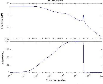
Fig 1.Open loop bode response of attitude.
It has been found that there is an unwanted flexible dynamics at 39.7 rad/s as shown in figure 1. The system is unstable with an infinite gain margin and phase margin at 3.44 rad/s is -2.65.
III.LQRCONTROLLER
Linear Quadratic Optimal Control Theory (LQR) is the most important and most comprehensive of a class of optimization based synthesis problem to obtain the performance index function by not only taking into account the performance requirements but also energy requirements. Quadratic performance measures have been extensively used in the design of optimal control systems because of its mathematical tractability and the ability to accommodate realistic functions such as energy functions and squared errors or deviations. When squared errors are used as performance measures, larger errors are given a much higher penalty than smaller errors as the squares of large quantities are very large and squares of small quantities are very small.
Consider a plant having a linear state equation. In the optimal control problem, it is desirable to determine a control signal that will minimize the performance measure. The optimal control is derived as:
u
Kx
(
t
)
where K is theoptimal gain matrix. The performance measure to be minimized is taken as
J
[
x
TQx
u
TRu
]
dt
0
. Here Q ispositive semi definite while R is positive definite.
Finally after mathematical analysis, the linear optimal feedback gain matrix is obtained as
K
R
1B
TP
, where P(t)is obtained after solving the equation
1
0
Q
P
B
PBR
PA
P
A
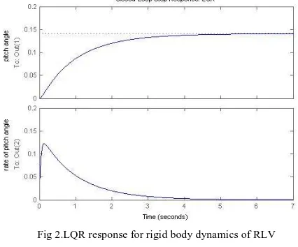
T T .In simulation, in both the cases R is taken as 1. Q is taken as gain multiplied by the transpose of C matrix with C matrix. The gain is taken as 1 in flexible plant simulation while the gain is taken as 2 in rigid body simulation. In both the cases the output is found to give stable response with a settling time of 4.41s for attitude in rigid body dynamics and a settling time of 4.95s for attitude in flexible RLV.
Fig 2.LQR response for rigid body dynamics of RLV
Fig 3.LQR response of flexible RLV
IV.PDCONTROLLER
Fig 4.Closed loop system with plant and rigid body dynamics
Fig 5.Step response of PD controlled nominal plant(
) Fig 6.Step response of PD controlled nominal plant(
).V. FLEXIBILITYDYNAMICSSTABILIZATIONUSINGNOTCHFILTER
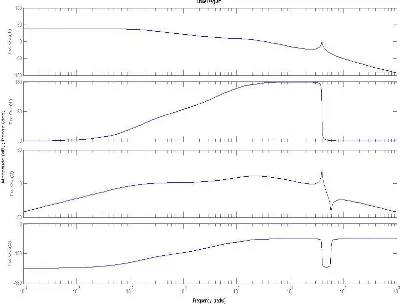
The frequency response of the rigid body including the flexibility dynamics is shown in the figure. The presence of flexibility dynamics degrades the controller performance and even drives the system to instability.
Fig 7.Open Loop Frequency response of attitude and rate of attitude
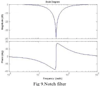
The use of a PD controller alone cannot stabilize the flexible RLV dynamics. When the flexible RLV plant is simulated, it is found that there is a bending mode at frequency 39.7rad/s. In order to stabilize the plant, a notch filter is designed at this frequency. A notch filter is used for attenuating the signal at one particular frequency. The transfer function of a typical notch filter is given as follows:
2 2
2
2 1
2
2
2
.
n n
n n
s
s
s
s
F
T
Here
nis the natural frequency,
1and
2are the damping values.2 1
denotes the depth of the notch.
Fig 8.Bode plot of PD controlled flexible launch vehicle
This is the method of bending mode stabilization using gain stabilization. Usually gain stabilization is used for stabilizing higher order bending modes. A notch filter is designed as follows:
By taking , .
The frequency plot of notch filter is given by figure 9.
Fig 9.Notch filter
VI. CONTROLSIGNALWITHANDWITHOUTNOTCHFILTER
Before the output of the plant is analyzed, the control signal is analyzed. The plant is analyzed in an open-loop fashion for observing the input to the plant. The control signal is found to have unwanted dynamics as shown in figure 10. The output of the notch filter is found to attenuate these unwanted dynamics at that frequency as shown in figure 11.
1586
66
.
79
1586
7966
.
)
(
22
s
s
s
s
s
F
1
01
.
0
83
.
39
2 1
Fig 10.Control signal with PD controller Fig 11.Control signal with PD-Notch filter
VII. PDCONTROLLERWITHNOTCHFILTER
The gain stabilized PD controller is capable of stabilizing the flexible RLV dynamics. The frequency response shows that very good stability margins are achieved. The step response shows that it is similar to rigid body dynamics.
Fig 12.Step response of PD-Notch controlled plant (
) Fig 13.Step response of PD-Notch controlled plant (
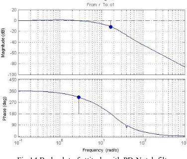
)Fig 14.Bode plot of attitude with PD-Notch filter
VIII. DISTURBANCEOBSERVERBASEDPDCONTROL
Disturbance Observer:
Disturbance observer is used to estimate the disturbance. This disturbance is fed back and added along with the outputs from other parts of whole system. The disturbance observer can estimate not only the external disturbance but also the internal disturbances caused by uncertainties. Consider a SISO linear system depicted by the following frequency domain form:
)]
(
)
(
)[
(
)
(
s
G
s
U
s
D
s
Y
P
Where Y(s) is the controlled output, U(s) is the control input; D(s) is the disturbance and
G
p(
s
)
is the model of theplant.
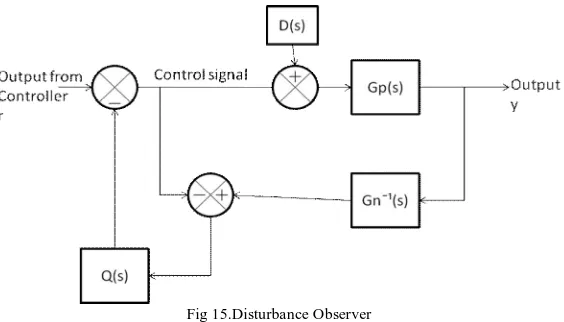
The block diagram of a disturbance observer in frequency domain is given as shown in figure 15.
Fig 15.Disturbance Observer
In the figure
G
n(
s
)
represents the nominal plant and Q(s) represents the filter of disturbance observer. Here the selection of Q(s) is an important thing. It is usually taken as a low pass filter. Also Q(s) is taken in such a way that it’s steady state gain is one and the relative degree is greater thanG
n1(
s
)
. These conditions should be ensured before implementing the disturbance observer. The mathematical proof can be shown below:The output can be represented as
)
(
)
(
)
(
)
(
)
(
s
G
s
U
s
G
s
D
s
Y
uy c
dyWhere
)]
(
)
(
)[
(
)
(
)
(
)
(
)
(
s
G
s
G
s
Q
s
G
s
G
s
G
s
G
n P n n P uy
)]
(
)
(
)[
(
)
(
)]
(
1
)[
(
)
(
)
(
s
G
s
G
s
Q
s
G
s
Q
s
G
s
G
s
G
n P n n P dy
When the filter is selected as a low pass filter, when frequency tends to zero Q(s) tends to one, hence we get
0
)
(
lim
)
(
)
(
lim
0 0
j
G
j
G
j
G
dy n uyFig 16.General Disturbance Observer or Estimation Filter
The equivalent structure of a general disturbance observer is shown in the figure 16. The control signal to the plant is found to have the inverted disturbance as shown in figure 17. This when added to the original disturbance gets cancelled off and hence the stability of the plant is assured.
The control signal plots and the output plots of the general disturbance observer are as shown in figures 17 and 18.
Fig 17.Control Signal Fig 18.Output
The control signal is having the exact inverted flexible dynamics at 39.7 rad/s. This when given to plant, will result in a stabilized response.
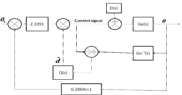
Disturbance Observer Based PD Control:
Once the disturbance observer based PD controller was implemented, it was found that the system was stabilized. The step response of attitude was found to have a settling time of 5.25s, rise time of 0.381s and a steady state error of 0.5% as shown in fig.20.
Fig 20.The step response of attitude Fig 21.The step response of attitude rate
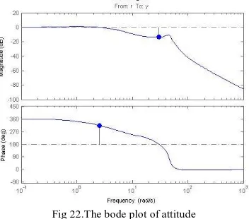
The frequency response was found to have a closed loop stable response having specifications with a gain margin of 13.3dB and a phase margin of 135rad.
Fig 22.The bode plot of attitude
If the bending mode parameters are not certain, the notch filter fails to attenuate it completely whereas a disturbance observer is capable of estimating and stabilizing the flexible plant even in the presence of uncertainties. Not only bending mode uncertainties but the effect of any other parameter changes can also be compensated by using the disturbance observer since it makes the actual plant behave like a nominal one by cancelling the mismatch between the two.
IX.CONCLUSION
Here a disturbance based observer based controller is designed for a flexible RLV in atmospheric phase. Though the performance of DOBC is similar to that of classical gain stabilized controller, in case of uncertainty in bending mode parameters, the gain stabilized controller needs to be re-designed but a disturbance observer performs well under parameter variations. Hence, it is a better method compared to the classical gain stabilization technique.
Of the second International Conference on Electrical and control Engineering, Yichang 2011,Science and Technology Aircraft control laboratory,Beihang University, Beijing 100191, P.R.China.
[6] WU Yunjie, LIU Xiaodong, TIAN Dapeng ”Research of Compound Controller for Flight Simulator with Disturbance Observer”, Chinese
Journal of Aeronautics, Science and Technology on Aircraft Control Laboratory, School of Automation Science and Electrical Engineering,Beihang University, Beijing 100191, China.
[7] Ping Zhou, Shao-Wen Lu, Wei Dai, Tian-You Chai,”Improved Disturbance Observer Design and Its Application”, 2012 24th Chinese Control
and Decision Conference (CCDC),State Key Laboratory of Synthetical Automation for Process Industries, Northeastern University, Shenyang 110819, China.
[8] Jianshuang Song, Xun Song,Zhang Ren,” New Integrated Robust disturbance rejection control method for RLV attitude controller design”, in
Proc. Of the second International Conference on Electrical and control Engineering, Yichang 2011,Science and Technology Aircraft control laboratory,Beihang University, Beijing 100191, P.R.China.
[9] Bong Keun Kim and Wan Kyun Chung, Member, IEEE.,” Advanced Disturbance Observer Design for Mechanical Positioning Systems,” IEEE
Transactions on Industrial Electronics, Vol. 50, No. 6, December 2003.
[10] Zhongliang He, Wei Xie,”Improved Disturbance Observer Based Control Structure”, 2009 Chinese Control and Decision Conference (CCDC
2009),College of Automation Science and Engineering,South China University of Technology,Guangzhou, 510640 China.
[11] S.H.Li, and J.Yang,”Robust autopilot design for bank-to-turn missiles using disturbance observers,” IEEE Transactions on Aerospace and
Electronic Systems, vol.49, no.1 ,pp.558-579, January 2013.
[12] J.Yang, S. Li.C. Sun and L.Guo,”Nonlinear disturbance observer based robust flight control for air-breathing hypersonic vehicles,” IEEE
Transactions on Aerospace and Electronic Systems, vol.49, no.2 ,pp.1263-1275,April 2013.
[13] Wen-Hua Chen, “Robust control of uncertain flexible spacecraft using disturbance observer based control strategies,”Proceedings of the 6th
International ESA Conference on Guidance,Navigation nd Control Systems, Greece pp.17-20 October 2005.
[14] Jae Weon Choi,Jang Gyu Lee,Man Hyung Lee,Hideto Suzuki, Takashi Suzuki,”On an attitude stabilizing condition for a Launch Vehicle”,
SICE ’95, Proceedings of the 34th SICE Annual Conference.
[15] Javer Romo,Teresa Alvarez,”Design of Attitude control and flight path for a launch vehicle”, International Conference on UKACC 2010,
Department of Engineering Science and Automatic Control, Escula de Ingenierias Industriales(Sede Doctor Mergelina) Universidad de Valladoid, Valladoid, Spain.